Sun Nuclear MapCHECK 3 User manual

Your Most Valuable QA & Dosimetry Tools
MapCHECK®3 User Guide
The New Benchmark for 2D IMRT QA
Model 1178

ii
User Guide, MapCHECK®3
© Copyright 2017-2019 by Sun Nuclear Corporation. All rights reserved.
The information contained in this guide and the accompanying software program are copyrighted
and all rights are reserved by Sun Nuclear Corporation. Copying, duplicating, selling, or otherwise
distributing any part of this product without the prior written consent of Sun Nuclear Corporation
is prohibited.
Sun Nuclear Corporation reserves the right to make periodic modifications to this guide without
obligation to notify any person or entity of such revision.
This guide is written for:
MapCHECK 3 Firmware version: 1.0.0.8
MapCHECK 3 FPGA Firmware version: 1.0.0
SNC Patient Software version: 8.2
MapCHECK®3, SunPoint®2, SNC Patient™ Software, and MapPHAN™ are trademarks of Sun
Nuclear Corporation. Other trademarks or tradenames are the property of their respective
owners. Solid Water®is a registered trademark of Gammex Inc., a wholly owned subsidiary of
Sun Nuclear Corporation.
Document 1178012, Rev C-1, 25 January 2019
Sun Nuclear Corporation
3275 Suntree Boulevard
Melbourne, FL 32940 USA
+1-321-259-6862
www.sunnuclear.com

Preface iii
Preface
Intended Use
Model 1178 MapCHECK 3 is a two-dimensional (2D) radiotherapy beam dosimetry QA system
intended for the measurement of radiation dose distributions for the purpose of comparison with
a simulated dose distribution in the same phantom geometry as calculated by the treatment
planning system (TPS).
CAUTION: Federal law restricts this device to sale by or on the order of a qualified
radiation therapy professional, such as a medical dosimetrist, medical physicist, or
radiation oncologist for use in radiation oncology.
Description
The MapCHECK®3 device contains an array of 1,527 SunPoint®2 Diode Detectors that measure
ionizing radiation to simulate patient structure during delivery of a treatment plan dose. The SNC
Patient™ software displays the MapCHECK 3 measurement and compares the results against the
imported treatment plan.
For detailed SNC Patient software instructions, see the SNC Patient online Help or the SNC Patient
Software Reference Guide, available on the Sun Nuclear Support website (see Support Website
on page 15).
Quality and Regulatory Systems
Sun Nuclear meets worldwide standards, including ISO 13485, FDA 21 CFR 820 Quality System
Regulations, Health Canada's Medical Device Regulations, the European Medical Device Directive
93/42/EEC, and all other relevant country regulations. Sun Nuclear is certified and authorized to
affix the CE mark on products for marketing and distribution in the Member States of the European
Union.
Sun Nuclear’s quality systems registrar and European Notified Body for Class II medical products
is BSI. Sun Nuclear’s Class I medical products are listed in Europe with the Competent Authority
of Germany.
Sun Nuclear Corporation is an ISO 13485 certified
company.
Health and Safety Information
• Use only the power supply that is provided with the device; it is a medical grade power
supply.
• Never pull on a cable to disconnect it. Always grasp the plug or connector.
•The device is not intended to be used in an oxygen rich environment.
• Do not operate the device in any strong magnetic fields (i.e., MRI).
For instructions to report health or safety related concerns, see Reporting Health or Safety Related
Issues or Concerns on page 24.
WARNING: To avoid risk of electric shock, this equipment must only be connected to
a supply mains with protective earth (ground).

iv Preface
This page is intentionally left blank.

Contents v
Preface . . . . . . . . . . . . . . . . . . . . . . . . . . . . . iii
Intended Use . . . . . . . . . . . . . . . . . . . . . . . . . . . . . . iii
Description . . . . . . . . . . . . . . . . . . . . . . . . . . . . . . . iii
Quality and Regulatory Systems. . . . . . . . . . . . . . . iii
Health and Safety Information . . . . . . . . . . . . . . . . iii
Section 1. Introduction . . . . . . . . . . . . . . . . . . 1
Parts . . . . . . . . . . . . . . . . . . . . . . . . . . . . . . . . . . . . 1
Products, Options and Accessories . . . . . . . . . . . . 1
MapCHECK 3 Quick Start Procedure . . . . . . . . . . . 2
Setup . . . . . . . . . . . . . . . . . . . . . . . . . . . . . . . . . . . . 3
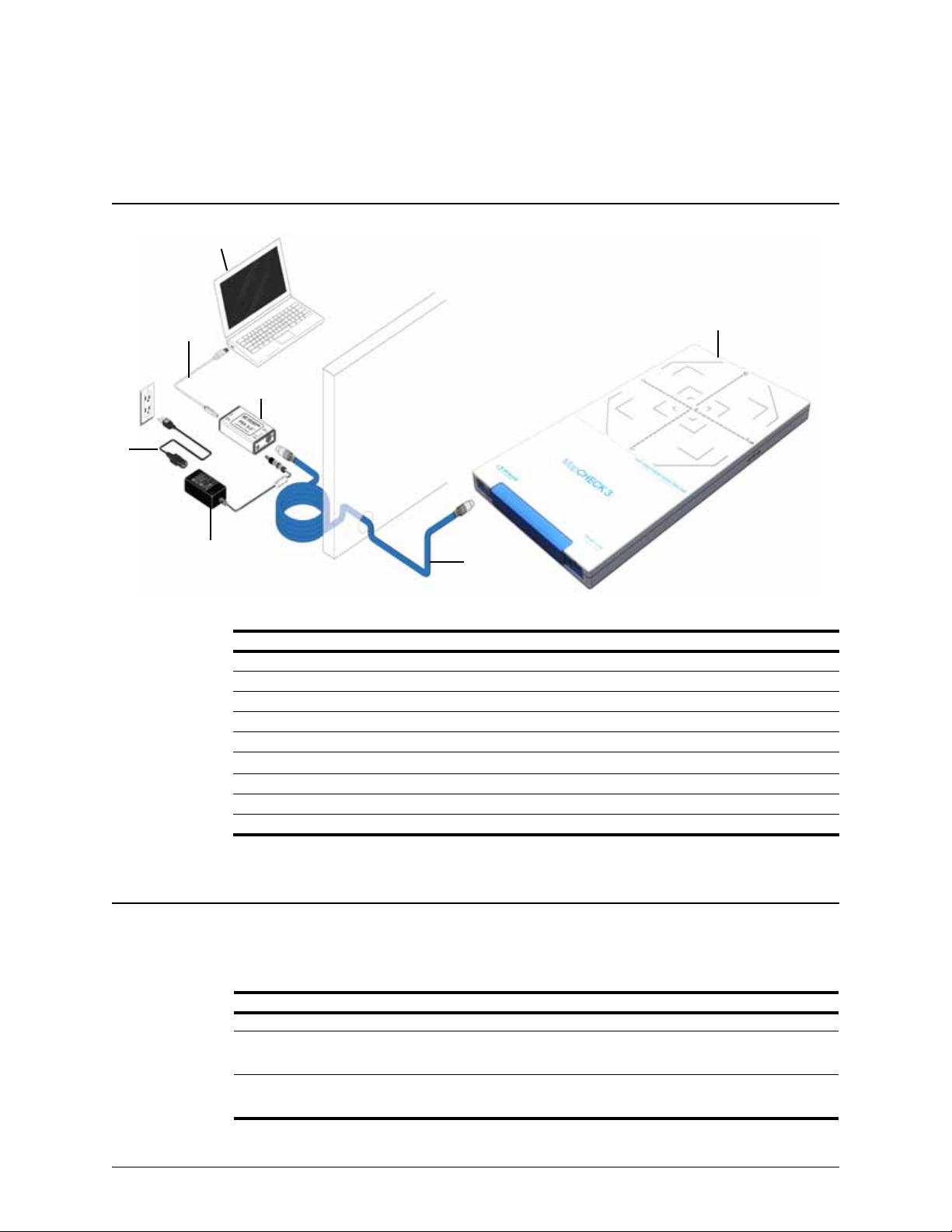
Connect Hardware and Launch Software . . . . . 3
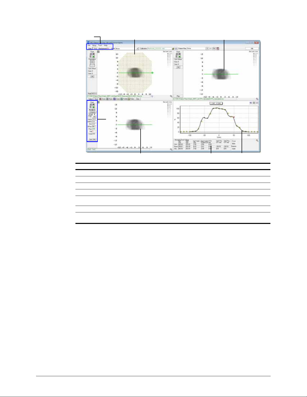
Overview of SNC Patient Software . . . . . . . . . . 4
Section 2. Operation . . . . . . . . . . . . . . . . . . . . 5
Temperature Equilibrium. . . . . . . . . . . . . . . . . . . . . 5
Background Measurement . . . . . . . . . . . . . . . . . . . 5
Array Calibration . . . . . . . . . . . . . . . . . . . . . . . . . . . 5
Array Calibration Conditions. . . . . . . . . . . . . . . . 5
Array Calibration Modes. . . . . . . . . . . . . . . . . . . 5
Flattening Filter Free (FFF) Beams . . . . . . . . . . . 6
Array Calibration Procedure . . . . . . . . . . . . . . . . 6
Recalibration Interval . . . . . . . . . . . . . . . . . . . . . 6
Absolute Dose Calibration. . . . . . . . . . . . . . . . . . . . 6
Dose Rate. . . . . . . . . . . . . . . . . . . . . . . . . . . . . . 6
Absolute Dose for Static Deliveries . . . . . . . . . . . . 6
Determine the Known Dose. . . . . . . . . . . . . . . . 6
Recommended Method . . . . . . . . . . . . . . . . 6
Alternate Methods. . . . . . . . . . . . . . . . . . . . . 7
Deliver Absolute Dose Calibration
Measurement . . . . . . . . . . . . . . . . . . . . . . . . 7
Absolute Dose for Rotational Deliveries . . . . . . . . . 8
Determine the Known Dose. . . . . . . . . . . . . . . . 8
Deliver Absolute Dose Calibration
Measurement . . . . . . . . . . . . . . . . . . . . . . . . 9
Set Up File Manager . . . . . . . . . . . . . . . . . . . . . . . . 9
Creating a New Patient Plan. . . . . . . . . . . . . . . . 9
Adding Files to Patient Plan . . . . . . . . . . . . . . . . 9
Position MapCHECK 3 for Measurement . . . . . . . . 9
Measurement Without MapPHAN Accessory . . 9
Measurement with MapPHAN Accessory . . . . 10
Acquire Measurement . . . . . . . . . . . . . . . . . . . . . . 10
MapCHECK 3 Measurement File Formats . . . . 11
Import Planned Dose. . . . . . . . . . . . . . . . . . . . . . . 11
Compare Device Measured to Planned Dose . . . . 12
Section 3. Support and Maintenance . . . . . . 13
Hardware Maintenance . . . . . . . . . . . . . . . . . . . . . 13
Minimizing Radiation Damage . . . . . . . . . . . . . 13
Inspection . . . . . . . . . . . . . . . . . . . . . . . . . . . . . 13
Repair . . . . . . . . . . . . . . . . . . . . . . . . . . . . . . . . 13
Cleaning . . . . . . . . . . . . . . . . . . . . . . . . . . . . . . 13
Storage . . . . . . . . . . . . . . . . . . . . . . . . . . . . . . . 13
Disposal and Recycling. . . . . . . . . . . . . . . . . . . 13
Maintaining Firmware . . . . . . . . . . . . . . . . . . . . . . 14
Troubleshooting. . . . . . . . . . . . . . . . . . . . . . . . . . . 14
Shutdown. . . . . . . . . . . . . . . . . . . . . . . . . . . . . . . . 15
Contacting Sun Nuclear Support . . . . . . . . . . . . . . 15
Support Website . . . . . . . . . . . . . . . . . . . . . . . . 15
Warranty . . . . . . . . . . . . . . . . . . . . . . . . . . . . . . . . 15
Section 4. Hardware Reference. . . . . . . . . . . 17
Top and Bottom Panels . . . . . . . . . . . . . . . . . . . . . 17
Detector Array . . . . . . . . . . . . . . . . . . . . . . . . . . . . 18
Connector Panel . . . . . . . . . . . . . . . . . . . . . . . . . . 18
Status LED . . . . . . . . . . . . . . . . . . . . . . . . . . . . 19
Detector Plane Marking. . . . . . . . . . . . . . . . . . . . . 19
Section 5. Specifications . . . . . . . . . . . . . . . 21
System Requirements . . . . . . . . . . . . . . . . . . . . . . 21
MapCHECK 3 Specifications . . . . . . . . . . . . . . . . . 21
Appendix A: Regulatory Supplement . . . . . . 23
Sun Nuclear Corporation Symbols . . . . . . . . . . . . 23
Operator Responsibility . . . . . . . . . . . . . . . . . . . . . 24
Reporting Health or Safety Related Issues or
Concerns . . . . . . . . . . . . . . . . . . . . . . . . . . . . . . 24
Modifications to Equipment . . . . . . . . . . . . . . . . . 24
Interaction with Other Electrical Equipment . . . . . 24
Contents

vi Contents
This page is intentionally left blank.

Parts 1
1 Introduction
Parts
Figure 1-1. Parts Provided with MapCHECK 3
No. Part Number Qty Description
11178400Z 1MapCHECK 3
2801073Z 1Power and data cable, 8-pin DIN, M/M, 25 m (82 ft.), blue
3801041Z 1USB Cable, A-B male, 2 m (6.5 ft.)
4801008Z 1Line power cord, plug style based on shipping address
50224502Z 1Power supply, switching, 110-240 VAC, 50-60 Hz to 18 VDC, filtered
60224500Z 1Power Data Interface (PDI) 3.0
-- 1177150 1Storage and carry case (not shown)
-- 1178012 1MapCHECK 3 User Guide (this guide, not shown)
-- 0224011 1Bulletin 02-09, Power Data Interface (PDI) 3.0 (not shown)
Products, Options and Accessories
Additional products, options, or accessories may be included in the shipment depending on
purchase options.
PC (provided by
user)
1
2
3
4
5
6
Table 1-1. Optional Accessories for MapCHECK 3
Part Number Description
801074Z Power and data cable, 8-pin DIN, M/M, 40 m (131 ft.), blue
1177000-VZ
1177000-SZ
1177000-EZ
Isocentric Mounting Fixture
1122000-EZ
1122000-EAZ
1122000-VZ
Gantry Mounting Fixture

2Section 1. Introduction
The following documents provide information about MapCHECK 3 accessories:
• Isocentric Mounting Fixture or Gantry Mounting Fixture: IMF/GMF User Guide, P/N 1122014
•MapPHAN:MapPHAN User Guide, P/N 1083012
MapCHECK 3 Quick Start Procedure
Perform the following steps to begin using MapCHECK 3
1 Download software, license, manuals, and virtual CT images.
a. Log in to the Sun Nuclear Support site at www.sunnuclear.com/support (see Support
Website on page 15) and navigate to the product panel for your MapCHECK 3 (by serial
number).
b. In the Product Downloads panel, select Generate Software License and follow the on-
screen instructions to save the license file.
c. Under Download Type select Software (Current Version), and then download the
appropriate SNC Patient software version for your PC (32-bit or 64-bit).
d. Under Download Type select Documentation, and then download the SNC Patient Soft-
ware Reference Guide.
e. If you will use MapCHECK 3 to perform VMAT QA measurements during which the gantry
rotates around the phantom, download a virtual CT phantom of MapCHECK 3 in a Map-
PHAN accessory. Select Download Type > CT Data, and then select the virtual phantom
that matches the buildup of your MapPHAN (5 cm or 10 cm). Each virtual phantom
includes an RT Structure that provides density overrides for each region.
2 Right-click the downloaded software executable and select Run as Administrator. When
prompted for the location of the license file, move the license file into the default directory
displayed on-screen. The software is now ready for use.
3 Set up MapCHECK 3 and connect cables. See Setup on page 3.
4 Using SNC Patient software, perform array calibration in ‘Standard’ mode. See Array
Calibration on page 5.
5 Using SNC Patient software, perform absolute dose calibration. See Absolute Dose
Calibration on page 6.
6 Using your TPS software, plan a static 10 cm x 10 cm field (or machine-specific reference) on
the MapCHECK 3 phantom and export DICOM RT Dose and RT Plan files.
7 Set up the MapCHECK 3 to the linac using the same setup as Step 6. See PositionMapCHECK
3 for Measurement on page 9.
1122-AZ Adapter plate for Gantry Mounting Fixture
1083000-0
1083000-1
Homogeneous water equivalent phantom that holds MapCHECK 3 at isocenter for
rotational dosimetry
• Model 1083 MapPHAN™ 5 cm
• Model 1083 MapPHAN™ 10 cm
1174105Z Solid Water® HE 30.0 cm x 35.2 cm x 0.5 cm buildup plate
1174106Z Solid Water® HE 30.0 cm x 35.2 cm x 1.0 cm buildup plate
1174107Z Solid Water® HE 30.0 cm x 35.2 cm x 2.0 cm buildup plate
1174108Z Solid Water® HE 30.0 cm x 35.2 cm x 5.0 cm buildup plate
WARNING: Use only parts and accessories supplied by Sun Nuclear for use with
MapCHECK 3. Use of other devices may result in incorrect measurements.
Table 1-1. Optional Accessories for MapCHECK 3 (Continued)
Part Number Description
Note: Each image in the virtual CT phantom is 512 x 512 pixels to allow use in most
treatment planning systems.

Setup 3
8 Using SNC Patient software, click Start and then turn on the beam. When the beam turns off,
click Stop. The radiation dose distribution is displayed in Set 1. See Acquire Measurement on
page 10.
9 Right-click in the Set 2 panel, select Open DICOM Plan/Dose File Set from the right-click
menu, select the DICOM data that you exported in Step 6, and then click Open. The planned
dose appears in Set 2. See Import Planned Dose on page 11.
10 Compare the MapCHECK 3 measurement to the planned dose. See Compare Device
Measured to Planned Dose on page 12.
If device measured to planned dose comparisons do not exhibit a satisfactory level of
agreement, investigate these differences as described in Eliminating Sources of Error in the
SNC Patient Software Reference Guide or online Help.
Setup
Connect Hardware and Launch Software
1Verify that the power source matches the power requirements. The power source must be
earth grounded.
2 Connect cables as shown in Parts on page 1. Route the 25 m power and data cable from the
control room to the treatment room such that it does not present a trip hazard.
3 Right-click SNC Patient desktop icon and select Run as administrator.
• The software checks the license and verifies computer hardware requirements.
• The software finds the connected device and then initiates a background measurement.
During the background measurement, each detector is checked for leakage. If leakage
exceeds the specified threshold, the detector is automatically disabled and a warning is
displayed.
Note: The MapCHECK 3 must be used with the provided PDI 3.0, blue power and data
cable, and PDI power supply. Other PDI devices (such as PDI 2.0) and other power and
data cables (such as the gray cable) are not supported for use with MapCHECK 3.
PDI 3.0 and the blue PDI power and data cable are compatible with all Sun Nuclear
products that use a PDI device.
CAUTION: If a system hardware warning is displayed, the computer hardware should
be upgraded as soon as possible. Otherwise, multi-frame measurement files may
display ‘missed’ updates, which could affect various analyses that require real-time
data.

4Section 1. Introduction
Overview of SNC Patient Software
Figure 1-2. Example of MapCHECK 3 Data Displayed in SNC Patient Software
No. Description
1Menu and toolbar
2Set 1 panel – displays device measured data or other data types
3Set 2 panel – displays planned dose data or other data types
4Profile and Histogram panel – displays a profile across a selected axis or displays a histogram
5Dose Summary/Statistics panel – displays absolute dose values or gamma/dose difference summary
index
6Compare panel – compares the data loaded in Sets 1 and 2
7Analysis panel – select analysis type, analysis criteria, and comparison results displayed in
Compare panel.
1 2 3
456
7

Temperature Equilibrium 5
2 Operation
Temperature Equilibrium
The MapCHECK 3 should be at the same temperature as the treatment room before use. If the
MapCHECK 3 is not stored at treatment room temperature, allow the device to reach temperature
equilibrium before acquiring measurements.
Temperature in the MapCHECK 3 detector array will remain stable when the device is continuously
connected to AC power; the device can remain connected to AC power in the treatment room
provided that the electronics area of the device does not receive direct radiation.
MapCHECK 3 measures temperature change in the detector array and applies temperature
correction to dose calculations.
Background Measurement
A background measurement is collected at software launch to establish the background
correction factor for each detector. SNC Patient software also evaluates MapCHECK 3
measurements while the beam is off and updates background correction factors if beam off
intervals of sufficient duration are found.
After background is completed and stored, the Background box displays “Yes” in green text. If the
‘Background’ box in the toolbar displays “No” in red text, collect a background measurement by
selecting Setup > Collect Background from the menu. The background period can be anywhere
from 30 to 300 seconds.
Ensure that the beam is off when measuring background. If the radiation measurement threshold
is exceeded during background measurement, the process stops and the previous approved
background is applied.
Array Calibration
Array calibration determines relative sensitivity differences between MapCHECK 3 detectors and
stores them as individual correction factors to be applied to the raw net measurement signals
from each detector.
Array Calibration Conditions
For optimal results, it is recommended to perform one array calibration per beam energy and with
the same buildup planned for measurement.
Array Calibration Modes
SNC Patient for MapCHECK 3 has three array calibration modes:
• Standard (IMRT) — Select this option for QA measurements collected with the beam
normal to the surface of the device and exposure for all angles administered at the same
angle i.e., beam straight down, anteroposterior (AP).
• Rotational (VMAT) — Select this option for QA measurements of IMRT or rotational
deliveries. This mode includes the same steps as Standard (IMRT) array calibration as
well as the following steps:
• Posteroanterior (PA) measurements to generate angular dependence correction factors.
• Open field measurements with MapCHECK 3 in MapPHAN.
• MapPHAN Factor — Select this option to modify the last two steps of a completed VMAT
array calibration for one of the following reasons:
• To generate a VMAT array calibration for each MapPHAN accessory (5 cm and 10 cm).

6Section 2. Operation
• To generate calibration factors for FFF beams. Repeating the last two steps of the VMAT
array calibration process under an FFF beam updates the calibration factors for FFF
fields.
Flattening Filter Free (FFF) Beams
Do not use a flattening filter free (FFF) beam during Standard or VMAT array calibrations. For FFF
(e.g., 6 FFF) array calibrations, perform calibration with flattening filter equivalent (e.g., 6 MV) open
fields, and then perform a MapPHAN Factor calibration to update the calibration factors for FFF
fields. See Array Calibration Modes on page 5.
Array Calibration Procedure
1 In the SNC Patient menu, select Setup > Calibrate Array.
2 Follow the initial setup instructions in the Array Calibration dialog box and then click Begin.
3 In the Measurement Parameters dialog box, select one of the following Array Cal Modes:
• Standard (IMRT). Rotational (VMAT), or MapPHAN Factor
• Beam energy
• MapPHAN type (None, 5 cm, or 10 cm).
A MapPHAN accessory is required to use the ‘VMAT’ and ‘MapPHAN Factor’ array calibration
modes. See Measurement with MapPHAN Accessory on page 10.
4 Click OK and follow the on-screen instructions.
Recalibration Interval
Absolute Dose Calibration
The absolute dose calibration procedure consists of collecting a MapCHECK 3 measurement
under the conditions at which dose delivered to the central detector is known and entering the
value of that known dose in the calibration wizard. SNC Patient software correlates the counts
collected by the device during the calibration to the known dose entered by the user, establishing
the absolute dose calibration factor.
Dose Rate
The radiation response of MapCHECK 3 diodes varies by up to ±1.5% with change in dose rate
(100 MU/min to 1400 MU/min). Therefore, dose calibration should be performed at the dose rate
that is similar to that at which QA measurements will be performed. This is especially important
for flattening-filter-free (FFF) energy modes, for which the range of available dose rates is wide.
For best results, it may be necessary to create more than one dose calibration for the same energy
mode - e.g., 6 MV FFF low dose rate calibration for VMAT measurements and 6 MV FFF high dose
rate calibration for IMRT or machine QA measurements. Performing the absolute dose calibration
at a dose rate that is significantly different from that of QA measurements can result in an error in
absolute dose reported by MapCHECK 3.
Absolute Dose for Static Deliveries
MapCHECK 3 is designed to collect measurements with the beam normal to the front surface of
the device (e.g., machine QA measurements or collapsed-angle IMRT QA). A MapPHAN is not
required to collect these types of measurements.
Determine the Known Dose
Recommended Method
1 Set up a water-equivalent phantom in a commissioned treatment planning system.
CAUTION: Annual array calibration is recommended but not required. Test array
calibrations annually and more frequently if the instrument is heavily used.

Absolute Dose for Static Deliveries 7
2 Create a beam with a field size of 10 cm x 10 cm. For machines that do not support 10 cm x
10 cm field size, use machine-specific reference field size.
3 Ensure the buildup over the isocenter accounts for the additional intrinsic buildup over
MapCHECK 3 detector plane (1.5 g/cm2).
For example, if dose calibration measurement will be performed with 5 cm of total water-
equivalent buildup, set the isocenter at the depth of 5 cm for dose calculation, with 3.5 cm
water equivalent buildup placed on top of MapCHECK 3 for the measurement.
4 Include at least 3 cm of water-equivalent backscatter material downstream from isocenter.
5 Set prescription to deliver 100 monitor units for 1 fraction.
6 Calculate plan and record dose at isocenter.
7 If desired, verify calculated dose by performing an ion chamber measurement under the same
conditions.
Alternate Methods
•AcquireaCTimageofMapCHECK 3 with desired buildup and import into TPS in lieu of
creating a water-equivalent phantom.
• Calculate known dose using a hand calculation or second-check software. The accuracy of
this method greatly depends on the fidelity of the PDD, TPR, and output factor data and any
conversions, interpolation, or corrections applied.
• Measure the known dose directly using a calibrated farmer-type ion chamber. Apply all
necessary corrections to minimize measurement uncertainty.
Deliver Absolute Dose Calibration Measurement
1 Set up MapCHECK 3 such that the detector plane is positioned at the isocenter plane.
2 Align the anterior surface of the MapCHECK 3 to lasers or field cross-hair so that the center
detector is located at isocenter.
3 Place additional buildup to match the total water-equivalent thickness used when calculating
the known dose. For the example above, place 3.5 cm of water-equivalent buildup on top of
the MapCHECK 3 surface, for a total depth of 5 cm to the MapCHECK 3 detector plane.
4 Set the field size to 10 cm x10 cm (or machine-specific reference field size used for
determining the known dose).
5 In the SNC Patient toolbar, click Load Array Calibration , select the array calibration that
corresponds to the absolute dose calibration energy, and then click Open. The default path
to the array calibration files is C:\SNC\SNC Patient\factors\<serial number>.
6 In the SNC Patient menu, select Setup > Calibrate Dose and follow the on-screen
instructions to collect and save the absolute dose calibration measurement. See Figure 2-1
on page 8.

8Section 2. Operation
Figure 2-1. Dose Calibration Dialog Box
7 To select this absolute dose calibration as the default, click Set as Default.
8 Click Close to exit.
Absolute Dose for Rotational Deliveries
The MapPHAN accessory allows MapCHECK 3 to perform VMAT QA measurements during which
the gantry rotates around the phantom. It is recommended to use the virtual CT phantom of the
MapCHECK 3 in MapPHAN, provided by Sun Nuclear, for all MapCHECK 3/MapPHAN TPS
calculations.
Determine the Known Dose
1 Download a virtual CT phantom of MapCHECK 3 in MapPHAN from the Sun Nuclear Support
website. See Support Website on page 15.
2 Import images and structures into the TPS.
3 Set the isocenter to the locations marked by the fiducial markers. DICOM coordinates of the
isocenter are (0, 0, 0).
4 Verify that mass density overrides are set for each structure as defined in the provided
structures file and shown below.
• MapPHAN: 1.03 g/cm3
• MapCHECK 3: 1.30 g/cm3
• Virtual fiducials: 0.00 g/cm3
5 Create a beam with field size 10 cm x 10 cm incident on the anterior surface of the
MapCHECK 3 in MapPHAN. For machines that do not support 10 cm x 10 cm field size, use
machine-specific reference field size.
6 Set prescription to deliver 100 monitor units for 1 fraction.
7 Calculate plan and record dose at isocenter.
8 Save phantom for later reference.
Note: If linac output has changed since known dose was calculated, consider scaling
known dose based on current linac output.

Set Up File Manager 9
Deliver Absolute Dose Calibration Measurement
1 Insert MapCHECK 3 into MapPHAN and align to isocenter. See MeasurementwithMapPHAN
Accessory on page 10.
2 Set field size to 10 cm x 10 cm (or machine-specific reference field size used for determining
the known dose).
3 In SNC Patient toolbar, click Load Array Calibration , select the VMAT array calibration
that corresponds to the absolute dose calibration energy, and then click Open. The default
path to the array calibration files is C:\SNC\SNC Patient\factors\<serial number>.
4 In SNC Patient menu, select Setup > Calibrate Dose. The Dose Calibration dialog box opens.
See Figure 2-1 on page 8.
5 Follow on-screen instructions to collect and save the absolute dose calibration measurement.
If desired, scale the known dose by the linac output at the time of dose calibration.
6 To select this absolute dose calibration as the default, click Set as Default.
7 Click Close to exit.
Set Up File Manager
The File Manager feature in SNC Patient software is used to store patient data files in a single
location and group them by file type, such as Device Measured, TPS Calculated, DICOM RT Plan,
Images, etc. Each group of patient data files is referred to as a Patient Plan.
When a Patient Plan is selected in the SNC Patient toolbar, commands to load or open a file will
display a list of files in the Patient Plan that match the selected file type.
To access the File Manager feature, select File > File Manager in SNC Patient software or click
FM in the toolbar.
Creating a New Patient Plan
1 Click FM in the toolbar and select New Patient Plan for File Manager. The ‘File Manager:
New Plan’ dialog box is displayed.
2 Enter Patient ID and Plan ID and then click OK. The ‘File Manager’ dialog box opens.
Adding Files to Patient Plan
1 In the File Manager dialog box, click the heading of the file type to import.
2 In the Import dialog box, select the file and then click Open. To select multiple files, press
SHIFT or CTRL while selecting.
The files are copied to the Patient Plan.
3 Click CLOSE FILE MANAGER.
Position MapCHECK 3 for Measurement
For details about accessories. see See Products, Options and Accessories on page 1.
Measurement Without MapPHAN Accessory
A MapPHAN accessory is not required to collect measurements with the beam normal to the front
surface of the device (e.g., machine QA measurements or collapsed-angle IMRT QA).
As an alternative to the beam straight down setup, the MapCHECK 3 can be attached to the
accessory Gantry Mounting Fixture (GMF) or Isocentric Mounting Fixture (IMF).
1 Place MapCHECK 3 on treatment couch with +Y toward gantry.
2 Align lasers to the MapCHECK 3 X and Y markings. If the area of interest is not centered on
the beam central axis (CAX), such as an asymmetrical field, the MapCHECK 3 can be
positioned off-center. Record the X and Y shift from beam CAX; these values are required to
align to the TPS dose map.

10 Section 2. Operation
3 Adjust couch height until SDD (source-to-detector distance) is equal to SAD (source-to-axis-
distance). This can be done by aligning the detector plane indicator on the side of the
MapCHECK 3 to the coronal laser. See Detector Plane Marking on page 19.
4 Add enough buildup to the device’s inherent buildup to create total buildup equal to the
planned dose depth. The MapCHECK 3 is capable of physically supporting up to 30 g/cm2of
buildup. Do not exceed this amount.
Measurement with MapPHAN Accessory
The MapPHAN accessory envelops MapCHECK 3 with 5 cm or 10 cm of water-equivalent buildup
and allows MapCHECK 3 to be used for planar QA of a rotationally delivered plan.
If the plan to be delivered has a large proportion of dose delivered with gantry at 90 or 270
degrees, stand the MapCHECK 3/MapPHAN assembly on its side such that the MapCHECK 3 array
is perpendicular to the gantry at 90 or 270 degrees.
Perform the following steps to insert MapCHECK 3 in MapPHAN and align the assembly to
isocenter.
1 Insert MapCHECK 3 into MapPHAN.
a. Place MapPHAN on level surface then loosen four thumbscrews.
b. Lift top plate slightly then insert MapCHECK 3 all the way into MapPHAN cavity.
c. Gently tighten thumbscrews.
2 Place MapCHECK 3/MapPHAN assembly on couch and set up detector plane (indicated by
coronal lines on sides of MapPHAN accessory) to isocenter plane.
3 Set up detector plane (indicated by the coronal lines on the sides of the MapPHAN accessory)
to isocenter plane.
4 Align marks on anterior surface of MapPHAN to lasers or field cross-hair to place MapCHECK
3 central detector at isocenter.
Acquire Measurement
1 Close all non-essential applications on the computer.
2 In SNC Patient toolbar:
• Click Load Array Calibration , select the array calibration that corresponds to the
measurement type (Standard array calibration for deliveries where beam incidence is
normal to the surface of the array, or VMAT array calibration for rotational deliveries in
MapPHAN), and then click Open.
• Click the down arrow next to Dose and select the absolute dose calibration that
corresponds to the planned energy.
3 Place MapCHECK 3 in measurement position as described in Position MapCHECK 3 for
Measurement on page 9.
4 If the measurement will be stored in File Manager (see SetUpFile Manageron page 9), select
the appropriate Patient Plan from the SNC Patient toolbar.
5 If the Background toolbar displays “No”, select Setup > Collect Background, select a
background period and then click Collect.
6 Click Start. When status box displays ‘Waiting for beam’, deliver the plan. The status box
displays “Collecting data”. When the beam turns off, click Stop.
CAUTION: Applying the wrong array calibration or absolute dose calibration will
cause erroneous results.

Import Planned Dose 11
7 A ‘Measurement Parameter’ dialog box displays.
a. Select energy and delivery type (IMRT or VMAT), and then click OK.
• Select IMRT for deliveries where beam incidence is normal to the surface of the
array (e.g., collapsed-angle IMRT or machine QA measurements). Select VMAT for
deliveries where gantry rotates around the device.
b. The parameters entered in the dialog box are compared to the array calibration selected
in the toolbar. If the parameters match, post-measurement processing begins. Other-
wise, a message is displayed.
• If delivery type VMAT is selected but a Standard (IMRT) array calibration is loaded in
the toolbar, the software prompts you to select a VMAT array calibration.
• If delivery type IMRT is selected but a VMAT array calibration is loaded in the toolbar,
the software applies the AP corrections from the VMAT array calibration to the mea-
surement. The AP steps in a VMAT array calibration are identical to the AP steps in
Standard (IMRT) array calibration. For details, see Array Calibration on page 5.
8 If the ‘Save Data’ dialog box does not open automatically, select File > Save > Device
Measured. The default file name is the current date with an alpha character (such as 17-Oct-
2017-A). The default path is the File Manager Patient Plan selected in Step 4.
WARNING: Modify the filename to identify the treatment plan as well as any other
relevant information.
9 Click Save. The measurement results appear in Set 1.
MapCHECK 3 Measurement File Formats
By default, two types of files are saved for each MapCHECK 3 measurement, a text file (*.txt) and
a multi-frame (movie) file (*.mcm). A corrected movie file (*.mcmd) can also be saved by default
if the option is enabled in program preferences (select Setup > Program Preferences > Other).
•Movie — ASCII file with integrated raw counts for each detector for each 50 ms update. Each
row captures cumulative data since the start of the measurement.
•Text — tab-delimited file that captures dose with integrated correction factors.
•Corrected movie — ASCII file with all corrections required to use the Machine QA tools.
Import Planned Dose
SNC Patient software supports import of dose plans from DICOM and various treatment planning
systems.
1 VMAT only: Apply the patient’s treatment plan to the Sun Nuclear provided CT images and RT
Structure (already saved in TPS during absolute dose calibration).
2 Export DICOM data for the treatment plan from the TPS to the SNC Patient PC.
3 Copy DICOM data to the File Manager feature. See Adding Files to Patient Plan on page 9.
4 Right-click in SNC Patient Set 2 panel, select Open DICOM Plan/Dose File Set, and then
select DICOM RT Dose and DICOM RT Plan. Isocenter coordinates are extracted from the
DICOM RT Plan.
Note: Back up all measurement files on a regular basis.
Note: If treatment plans will be consistently inverted in X or Y direction relative to
device measurement, set up SNC Patient software to automatically invert treatment
plans upon import. Select Setup > Program Preferences. In Treatment Plan Import-
ing area, select the plan type. Select Invert X, Invert Y or both, and then click Set.

12 Section 2. Operation
5 If prompted for MU or scaling factor, enter the information needed to convert the proper
values to dose delivered.
• If the file already contains absolute dose values for a single fraction, enter a value of 1.
• If the file contains relative values, enter MUs.
• If the file contains dose values that must be scaled, enter the appropriate scaling factor.
For example, if the file contains total dose for all fractions, the scaling factor is 1 / (num-
ber of fractions). The default scaling factor is 1.0. Pinnacle dose files are often in relative
values and require MU.
Compare Device Measured to Planned Dose
In the Analysis toolbar, select the analysis type and criteria and then click Compare. The
comparison graph shows the detectors that failed the selected comparison criteria with the
following color code:
• Red indicates failing points where Set 1 dose values are greater than Set 2 dose values.
• Blue indicates failing points where Set 1 dose values are less than Set 2 dose values.
Figure 2-2. Analysis Panel Controls
WARNING: SNC Patient software interpolates planned dose data to 1 mm for DTA and
Gamma analysis. For best results in high dose gradient regions, initial grid spacing
should be ≤3 mm. If planned dose grid spacing is > 4 mm, import is prohibited.
Note: A message is displayed if the comparison reveals a significant difference in the
plan to angle calculation.
WARNING: Do not modify a patient’s treatment plan based only on the results from a
single QA device; but DO investigate the source of the error in the treatment delivery
device (TDD) or treatment planning system (TPS).
Compare button — click to compare Set 1 with Set 2.
Analysis Type:
• DTA/GC — selects Distance to Agreement (DTA) or Gradient Compensation (GC)
analysis. ‘GC’ is only displayed in the analysis toolbar if Gradient Compensation is
enabled in program preferences. GC analysis reduces dose difference by the product of
the local gradient and measurement uncertainty.
•— selects Gamma analysis.
• RD — selects Relative Dose analysis mode.
• AD — selects Absolute Dose analysis mode.
Analysis Criteria:
• TH (%) (threshold) — minimum dose percent value that must be met in either the device
measured or planned dose data for the point to be included in the analysis.
• Diff (%) — dose difference tolerance criterion.
• Distance (mm) — distance tolerance criterion.
Note: Enable ‘Apply Measurement Uncertainty’ option in program preferences to ensure
results are consistent with expected analysis type.
Comparison Results:
• %Pass — percentage of evaluated measurement points passing criteria.
• Pass — number of measurement points passing criteria.
• Fail — number of measurement points failing criteria.
• Total — measurement points included in the analysis.
Global % (Van Dyk % difference) — available when absolute dose analysis mode is
selected. Check the box to enable Global % difference, or uncheck to select local percent
difference.
Calc Shift — calculates the best alignment between the detectors and the beam that
results in a lower number of failed points.

Hardware Maintenance 13
3 Support and Maintenance
Hardware Maintenance
Minimizing Radiation Damage
The electronics are located between the “KEEP DIRECT BEAM ABOVE THIS LINE” marking and
the cable connection ports. To minimize damage to the electronics:
• Do not expose the device electronics to the direct beam.
• Do not leave MapCHECK 3 on the couch exposing to direct radiation during delivery system
warm up.
• If MapCHECK 3 is stored in the treatment room, ensure it is not exposed to direct radiation
when the gantry is rotated.
• Avoid frequent use of thick buildup which may cause scattered radiation and damage the
electronics.
Inspection
Periodically inspect MapCHECK 3 housing, casing, cables, connectors, and all ancillary parts for
damage. If any mechanical or electrical degradation is suspected, if errors are suspected, or if the
device cannot be calibrated to provide consistent measurements, discontinue use and contact
Sun Nuclear Support. See Contacting Sun Nuclear Support on page 15.
Repair
There are no user-serviceable parts in MapCHECK 3. If there are problem with the device or
ancillary parts or accessories, contact Sun Nuclear Support. See Contacting Sun Nuclear Support
on page 15.
Cleaning
Clean MapCHECK 3 by vacuuming or wiping with a clean, dry cloth. If necessary, clean external
surfaces with a cloth moistened with mild cleaning solution. Do not use any solvents or abrasive
cleaners.
Do not immerse MapCHECK 3 in any fluid. Do not permit liquid to flow on the device or any
associated parts or accessories, or into any cavity.
Storage
Store the device, ancillary parts, and accessories in an indoor, protected environment consistent
with conditions stated in Specifications on page 21.
Disposal and Recycling
The MapCHECK 3 contains electrical components. In some countries the disposal of electrical
components is subject to special requirements. When the components are no longer functional
or are otherwise ready to be discarded, recycle or dispose of them according to local waste
management or recycling regulations.
CAUTION: The MapCHECK 3 has dosimeters between the electronics and detector
array. The dosimeters are read when the MapCHECK 3 is returned for service. An indi-
cation of direct radiation to the electronics will VOID the warranty.

14 Section 3. Support and Maintenance
Maintaining Firmware
Although MapCHECK 3 contains the latest firmware version when shipped, upgrades may
become available to add features, improve operation, or correct issues. Firmware updates are
distributed with each software version. See the Firmware Upgrade instructions in the SNC Patient
Software Reference Guide or online Help.
Troubleshooting
Before requesting technical support, review the following troubleshooting information to see
whether the problem can be corrected.
Table 3-1. MapCHECK 3 Troubleshooting
Indication Possible Cause Remedy
MapCHECK 3
cannot commu-
nicate with
SNC Patient
software.
Wrong PDI or power and data cable. MapCHECK 3 must be used with PDI 3.0 and
the blue power and data cable. See Connect
Hardware and Launch Software on page 3.
USB cable not connected. Loose or missing cable connections. Check
cable connections. See Setup on page 3.
Damaged PDI or power and data cable. Contact Sun Nuclear Support. If you have
another Sun Nuclear instrument that uses a PDI
device, try connecting a different PDI 3.0 or
power and data cable.
Wrong FTDI driver version. SNC Patient software v7.0 installs FTDI driver
v2.8.24. Check the driver version using the pro-
cedures in Technical Bulletin 02-09, PowerData
Interface (PDI) 3.0. Select the v2.8.24 drivers
and then restart the computer.
Damaged wiring or connector. Inspect connectors and cables. If damage is
observed, contact Sun Nuclear Support
Damaged electronics. Inspect MapCHECK 3 housing. If damage is
observed, contact Sun Nuclear Support.
Incorrect
readings.
MapCHECK 3 positioned incorrectly. Correct MapCHECK 3 position with respect to
couch position.
Incorrect selection of dose or array
calibration.
Ensure that array and dose calibration are rele-
vant for the linac, energy, buildup, and type of
delivery.
Dose rate during patient QA significantly
different from that used during absolute
dose calibration.
Apply absolute dose calibration performed with
a similar dose rate to mitigate any measure-
ment non-linearity.
Failure to use Sun Nuclear approved CT
images of MapCHECK 3 in MapPHAN.
Calculate known dose in TPS software using
downloaded DICOM RT Structure and CT
images of MapCHECK 3 inserted in the Map-
PHAN. See Absolute Dose Calibration on
page 6.
Failure to override densities to those
defined in the DICOM RT Structure file.
Calculate known dose in TPS software using
downloaded DICOM RT Structure and CT
images of MapCHECK 3 in MapPHAN. See
Absolute Dose Calibration on page 6.
Large proportion of dose from gantry at
90 or 270 degrees.
Repeat measurement with MapCHECK 3 in
MapPHAN. Ensure MapCHECK 3/MapPHAN
assembly is rotated 90 degrees (stand on edge
of assembly).
Linac dose output variation. Perform independent verification of dose out-
put. Contact linac manufacturer for technical
support.
Crosshair or laser misalignment. Correct laser alignment.
Excessive
noise in
measurements.
Use of unsupported power supply. Use Sun Nuclear-provided medically rated
power supply.
This manual suits for next models
1
Table of contents
Other Sun Nuclear Medical Equipment manuals