Sun Yeh Electrical M Series User manual

SY04-C001A-EN
APP
(iOS / Android)

【M Series】Multi-turn Electric Valve Actuator
2021.06
1 General Information...............................................................................................................................1
1.1 Safety Instructions .....................................................................................................................1
1.2 Installation, Storage, Transport..................................................................................................1
2 Product Overview..................................................................................................................................2
2.1 Features......................................................................................................................................2
3 Product Mechanical Data.......................................................................................................................3
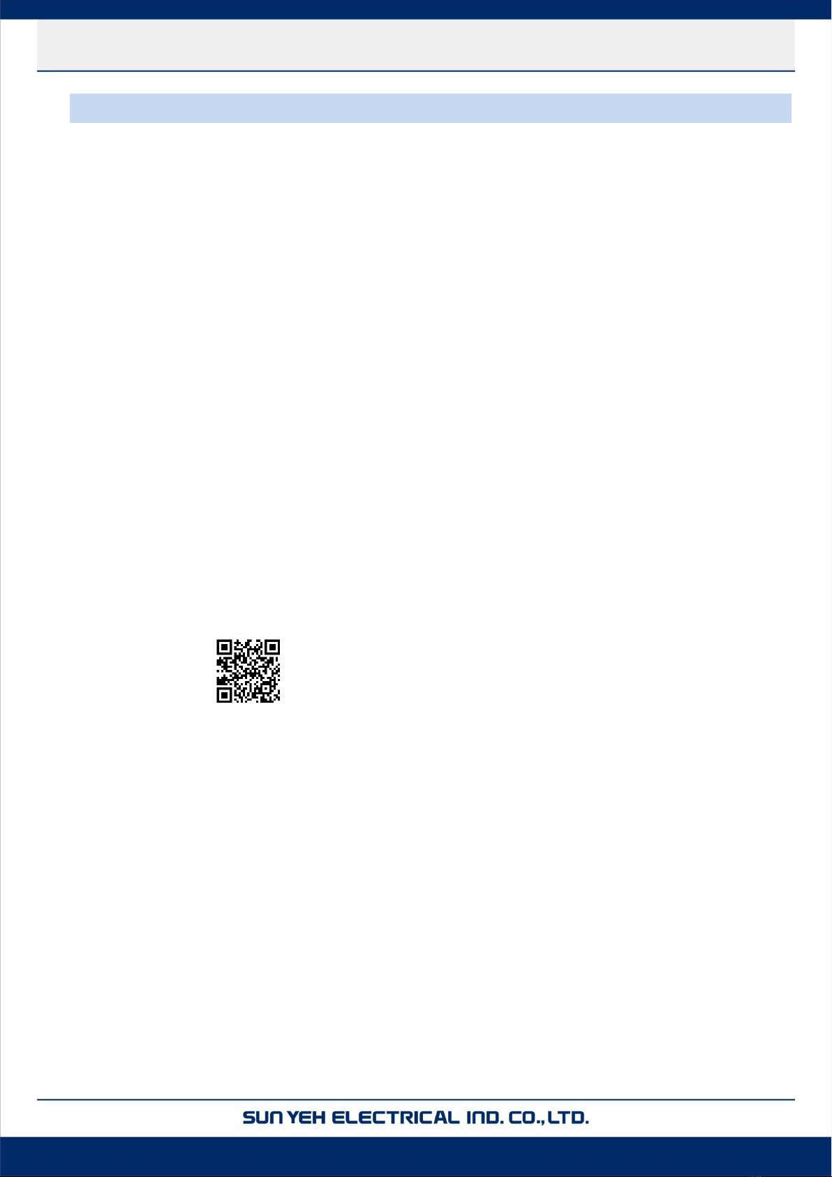
3.1 Parts Identification.....................................................................................................................3
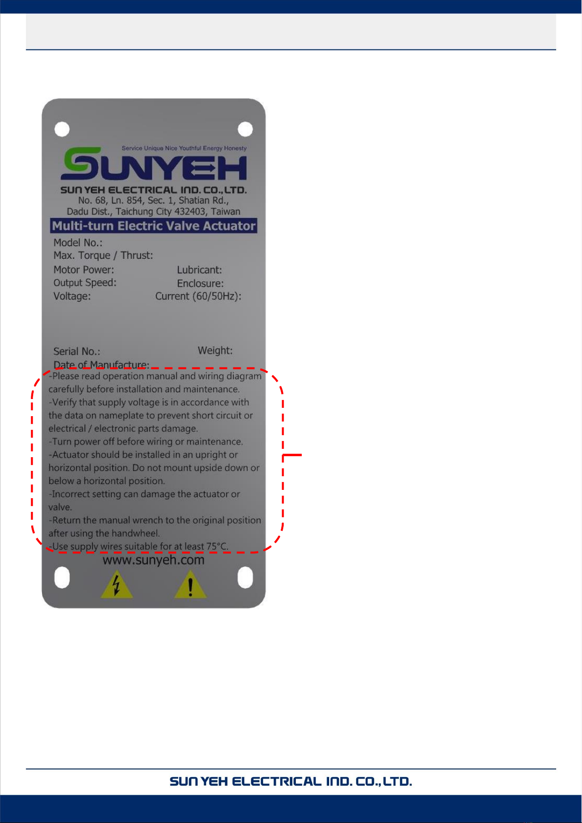
3.2 Nameplate Instruction................................................................................................................3
3.3 Technical Information................................................................................................................5
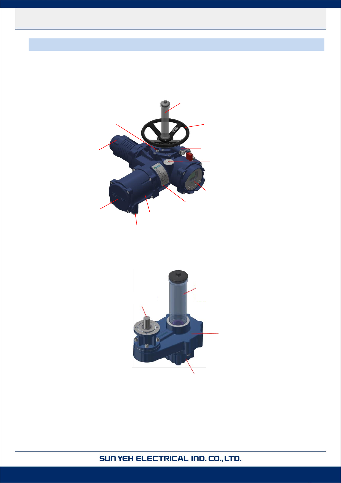
3.4 External Gear Box .....................................................................................................................5
4 Storage, Transport and Packaging .........................................................................................................7
4.1 Receiving / Inspection ...............................................................................................................7
4.2 Storage.......................................................................................................................................7
4.3 Transport....................................................................................................................................7
5 Mounting................................................................................................................................................8
5.1 Preparing Actuator Drive Bush..................................................................................................8
5.2 Mounting Actuator with Valve...................................................................................................9
5.3 Mounting Gear Box with Valve...............................................................................................11
5.4 Mounting Actuator with Gear box...........................................................................................13
5.5 Mounting Stem Protection Tube..............................................................................................14
6 Electrical Connection...........................................................................................................................15
6.1 Terminal Block Layout............................................................................................................15
6.2 Removing Terminal Cover.......................................................................................................16
6.3 Electrical Connection - Cable Connection ..............................................................................17
7 Manual Operation................................................................................................................................18
7.1 Manual Operation Steps ..........................................................................................................18
8 Electrical Operation.............................................................................................................................20
8.1 Introduction..............................................................................................................................20
8.2 User Management....................................................................................................................26
8.3 Operating .................................................................................................................................29
8.4 Monitoring.............................................................................................................................32
8.5 System Program.......................................................................................................................37
8.6 Maintenance Set.......................................................................................................................40
8.7 Parameter Set...........................................................................................................................42
8.8 Control Mode Set.....................................................................................................................56
8.9 Communication Set .................................................................................................................62
9 Servicing and Maintenance..................................................................................................................64
9.1 Battery Maintenance................................................................................................................64
Content

【M Series】Multi-turn Electric Valve Actuator
2021.06
9.2 Oil Replacement ......................................................................................................................65
9.3 Maintenance.............................................................................................................................66
9.4 Operation Protection................................................................................................................66
10 Troubleshooting...................................................................................................................................67
11 Warranty...............................................................................................................................................71

【M Series】Multi-turn Electric Valve Actuator
1
2021.06
Failure to follow safety instructions may cause serious injury, equipment damage, or void-
ed warranty.
1General Information
1.1 Safety Instructions
Installation, maintenance and repair works must be performed by trained personnel.
The Handling shall follow the safety and warning instruction contained in this manual.
The user should read and follow instructions contained in this operation manual included with
the product. Failure to do this may result in damages and void warranty. Sun Yeh will not
be liable for damages due to operator negligence or misuse.
Local health and safety regulation shall be complied with.
In a few cases, the surface temperature may exceed 60°C (140 ℉). Please check the surface
temperature before operation, using an appropriate thermometer and wearing protective
gloves before operation.
1.2 Installation, Storage, Transport
Please read operation manual and wiring diagram carefully before installation.
Perform all basic settings including stroke limitation for open and close direction prior to op-
eration.
Verify the power supply’s voltage is in accordance with the data on nameplate to prevent short
circuit or electrical/electronic parts damage caused by incorrect power input.
Turn power off before wiring or maintenance.
Connect the ground wire to PE point inside the electric actuator.
To avoid functional failure caused by static, do not touch any components on the PCBA with
metal tools or bare hands.
Use proper techniques when installing conduit and properly seal the connection to prevent
vapor condensation from entering the unit.
Actuator should be installed in an upright or horizontal position. Do not mount upside down
or below a horizontal position.
These units are not designed to operate in vacuum spaces or where an explosive atmosphere
exists.
Periodically inspect actuator enclosure to prevent dust from accumulating.

【M Series】Multi-turn Electric Valve Actuator
2
2021.06
2Product Overview
Sun Yeh M series multi-turn electric actuators are designed to provide output torque from 41 Nm
to 100 Nm (363 inlb to 885 inlb) and output speed from 15 rpm to 120 rpm which fit with various
types of valves. After combining with a gear box, the maximum output torque increases.
It comes standard with backlit LCD display and reed switches to make operation easily under dif-
ferent light conditions.
The manual override is equipped to enable the automatic operating mode switched to manual oper-
ation easily and stably, no matter under operation or during power outages.
2.1 Features
Five speeds can be chosen. The output torque remains constant when output speed changes.
High efficiency BLDC motor technology allows output torque and speed adjustable in both
directions.
Torque overload protection at each end of stroke.
Double-sealed and IP68 weatherproof.
Patent obtained in UK, USA, Taiwan, China, Japan, and Germany.
Setting, monitoring, and diagnosing are possible through local control and APP with Blue-
tooth.
(iOS / Android)
Available communication solutions: Modbus RTU RS485, Profibus DP V0.
Temperature of motor and electronic components is monitored.
Non-intrusive design allows setting and adjusting without cover removal.
Multi-language LCD display incorporated with reed switches makes operating, setting, ad-
justing easy and simple.
Automatic phase correction and phase loss protection.
Instantaneous reversal protection.
Four levels of assigned password protection hierarchical prevent unauthorized changes.

【M Series】Multi-turn Electric Valve Actuator
3
2021.06
3Product Mechanical Data
3.1 Parts Identification
Figure 1 Actuator
Figure 2 Gear Box
Control Box
Stem Protection Tube
Dust Proof
Thrust Base
(Rising Stem)
Gear Box
Dust-proof Stem Protection
Sleeve
Input Shaft
Figure 1 Actuator
Nameplate
Setting and Display Panel
Battery Sealing Plug
Handwheel Lever and Lock
Handwheel
Dust-proof Stem Protection Sleeve
Oil Plug
Motor
Terminal Cover
Conduit Entries
Control Room

【M Series】Multi-turn Electric Valve Actuator
4
2021.06
3.2 Nameplate Instruction
Caution

【M Series】Multi-turn Electric Valve Actuator
5
2021.06
3.3 Technical Information
Model
Output
Speed*
Non-rising stem
Rising stem
Mounting
Flange
Max
Torque
Max Stem
Acceptance
Diameter
Weight
Max Thrust
Max Stem
Acceptance
Diameter
Weight
rpm
Nm
inlb
mm
kg
lb
kgf
lbf
kN
mm
kg
lb
ISO 5210
M-41
40 - 120
41
363
35
52
115
4080
8996
40
28
55
121.5
F10
M-55
30 - 90
55
487
M-80
20 - 60
708
80
708
M-100
15 - 45
885
100
885
* There are five speeds can be chosen, refer to 8.7.4 (P.48) for setting.
3.4 External Gear Box
G201 Multi-turn Gearbox
Applicable
Actuator
Output
Speed
Non-rising stem
Rising stem
Mounting
Flange
Max
Torque
Max Stem
Acceptance
Diameter
Weight
Max Thrust
Max Stem
Acceptance
Diameter
Weight
rpm
Nm
inlb
mm
kg
lb
kgf
lbf
kN
mm
kg
lb
ISO 5210
M-41
13 - 40
123
1090
40
22
48.5
7140
15744
70
32
25
55.1
F12
M-55
10 - 30
165
1460
M-80
7 - 20
708
240
2125
G202 Multi-turn Gearbox
Applicable
Actuator
Output
Speed
Non-rising stem
Rising stem
Mounting
Flange
Max
Torque
Max Stem
Acceptance
Diameter
Weight
Max Thrust
Max Stem
Acceptance
Diameter
Weight
rpm
Nm
inlb
mm
kg
lb
kgf
lbf
kN
mm
kg
lb
ISO 5210
M-41
8 - 24
205
1815
45
25
55.1
10200
22491
100
36
27.5
60.6
F14
M-55
6 - 18
275
2435
M-80
4 - 12
708
400
3540

【M Series】Multi-turn Electric Valve Actuator
6
2021.06
G203 Multi-turn Gearbox
Applicable
Actuator
Output
Speed
Non-rising stem
Rising stem
Mounting
Flange
Max
Torque
Max Stem
Acceptance
Diameter
Weight
Max Thrust
Max Stem
Acceptance
Diameter
Weight
rpm
Nm
inlb
mm
kg
lb
kgf
lbf
kN
mm
kg
lb
ISO 5210
M-55
4.3 - 13
385
3410
60
32.5
71.6
15300
33737
150
44
36
79.4
F16
M-80
2.8 - 8.6
560
4960
M-100
2.1 - 6.4
708
700
6200

【M Series】Multi-turn Electric Valve Actuator
7
2021.06
4Storage, Transport and Packaging
4.1 Receiving / Inspection
Carefully inspect the package for any damages resulting from shipping and report all dam-
ages to the freight carrier and seller.
After unpacking the product and information packet, please keep the cartons and any pack-
ing materials in case of product return or replacement. Verify that the items on the packing
slip or on the bill of lading are the same as what were ordered. If there is any discrepancy,
please contact the seller.
Verify if the technical data on nameplate is in accordance with what was ordered.
4.2 Storage
The actuator should be stored in a dry area with relative humidity of less than 90 % and at
temperatures between -20 °C to +40 °C (-4 °F to +104 °F).
The product shall be stored with suitable protection from corrosive substance that can dam-
age the metal and insulating parts.
The plastics conduit plug for temporary protection should not be removed until the actuator
is ready to be cabled. Use suitable cable glands with IP68 protection.
4.3 Transport
Attach ropes or hooks to actuator housing only for the purpose of lifting by hoist and not to
hand-wheel.
Actuators packaged in cartons can be ship by stand up to land, sea, or air transportation.
Packaged actuators shall avoid of violent impact and strong vibrations and be protected from
rain or snow.
The actuator with the gearbox installed should be secured with a rope or hook in the gearbox
and actuator, when lifting the device.

【M Series】Multi-turn Electric Valve Actuator
8
2021.06
5Mounting
5.1 Preparing Actuator Drive Bush
a. Loosen M5 screws from the base assembly of the actuator or gearbox and dismantle the
components. Remove the drive bush from base assembly.
b. Machine the drive bush to suit the valve stem.
c. Reassemble the base assembly and fasten M5 screws.
Make sure if the screw hole is in the right position.
Screw Size
Torque (Nm)
M5
3
Figure 1
Non-thrust Base Assembly
(Rising Stem)
Figure 2
Thrust Base Assembly
(Non-Rising Stem)
Drive Bush
M5 Screw
Drive Bush
M5 Screw

【M Series】Multi-turn Electric Valve Actuator
9
2021.06
5.2 Mounting Actuator with Valve
Rising Stem
a. Apply a small quantity of grease to the valve stem【5】.
b. Screw the thrust base assembly【3】into the valve stem【5】until it is flush with the valve
flange. Then keep rotating the thrust base assembly【3】until alignment of the fixing
holes.
c. Fasten M10 screws【6】, but do not tighten completely.
d. Mount the actuator【1】with the thrust base assembly 【3】, to ensure the stem nut is
engaged with the output drive sleeve【2】(see photo on the right).
If the flanges are flush with each other, the actuator【1】will
be engaged with thrust base assembly【3】properly.
e. Adjust the actuator【1】until alignment of mounting holes on the
thrust base assembly【3】.
f. Use M10 screws【4】to fasten the actuator【1】with the thrust base
assembly【3】and fasten actuator screws (M10).
Screw Size
Torque (Nm)
M10
12.5
g. Tighten M10 screws【6】.
Screw Size
Torque (Nm)
M10
25
【1】Actuator
【2】Output Drive Sleeve
【3】Thrust Base Assembly
【4】M10 Screws
【5】Valve Stem
【6】M10 Screws
(Prepared by customer)

【M Series】Multi-turn Electric Valve Actuator
10
2021.06
Non-rising Stem
a. Use M10 screws【4】to fasten the non-thrust base assembly【3】with the actuator【1】.
Screw Size
Torque (Nm)
M10
12.5
b. Mount the actuator【1】with the valve stem【5】until it is flush with the valve flange..
c. Adjust the actuator【1】until alignment of the fixing holes and ensure
the stem nut of non-thrust base assembly 【3】is engaged with the
output drive sleeve【2】(see photo on the right).
If the flanges are flush with each other, the actuator
【1】will be engaged with the non-thrust base assembly【3】
properly.
d. Tighten M10 screws【6】.
Screw Size
Torque (Nm)
M10
25
Use suitable screws and couplings to direct mount with the valve.
DO NOT lift the actuator through the hand wheel while moving to
avoid actuator damage.
The basic setting is finished if the actuator is mounted with the valve
when ex-factory.
【1】Actuator
【2】Output Drive Sleeve
【3】Non-thrust Base Assembly
【4】M10 Screws
【5】Valve stem
【6】M10 Screws
(Prepared by customer)

【M Series】Multi-turn Electric Valve Actuator
11
2021.06
5.3 Mount Gear Box with Valve
Rising Stem
a. Apply a small quantity of grease to the valve stem【5】.
b. Screw the thrust base assembly【3】into the valve stem【5】until it is flush with the valve
flange. Then keep rotating the thrust base assembly【3】until alignment of the fixing
holes.
c. Fasten the screws【6】, but do not tighten completely.
d. Mount the gear box【1】with the thrust base assembly【3】to ensure the stem nut is
engaged with the output drive sleeve【2】(see photo on the right).
If the flanges are flush with each other, the gear box【1】will be
engaged with the thrust base assembly【3】properly.
e. Adjust the gear box【1】until alignment of mounting holes on the thrust
base assembly【3】.
f. Use the screws 【4】to fasten the gear box【1】with the thrust base
assembly【3】.
Gear Box
Screw Size
Torque (Nm)
G201
M12
21
G202
M16
53
G203
M20
102
g. Tighten the screws【6】.
Gear Box
Screw Size
Torque (Nm)
G201
M12
42
G202
M16
106
G203
M20
204
【1】Gear Box
【2】Output Drive Sleeve
【3】Thrust Base Assembly
【4】Screws
【5】Valve Stem
【6
】
Screws
(Prepared by customer)

【M Series】Multi-turn Electric Valve Actuator
12
2021.06
Non-rising Stem
a. Use the screws 【4】to fasten the non-thrust base assembly【3】with the gear box 【1】.
Gear Box
Screw Size
Torque (Nm)
G201
M12
21
G202
M16
53
G203
M20
102
b. Mount the gear box 【1】with the valve stem 【5】until it is flush with the valve flange.
c. Adjust the gear box【1】until alignment of the fixing holes and ensure the stem nut of
non-thrust base assembly【3】is engaged with the output drive sleeve【2】(see photo on
the right).
If the flanges are flush with each other, the gear box 【1】
will be engaged with non-thrust base assembly【3】
properly.
d. Tighten the screws【6】.
Gear Box
Screw Size
Torque (Nm)
G201
M12
42
G202
M16
106
G203
M20
204
【1】Gear Box
【2】Output Drive Sleeve
【3】Non-thrust Base Assembly
【4】Screws
【5】Valve Stem
【6】Screws
(Prepared by customer)

【M Series】Multi-turn Electric Valve Actuator
13
2021.06
5.4 Mounting Actautor with Gear box
a. Ensure that the O-ring【2】fits uniformly in the recess of the gear box.
b. Mount the actuator【1】with gear box【3】and align the input shaft of the gear box【3】.
c. Rotate the actuator【1】to let the flange hole of the gear box align with the flange hole
of the gear box【5】.
d. Tighten M10 screws 【4】per the table below.
Screw Size
Torque (Nm)
M10
12.5
【1】Actuator
【2】O-ring
【3】Input Shaft of Gear Box
【4】M10 Screws
【5】Gear Box

【M Series】Multi-turn Electric Valve Actuator
14
2021.06
5.5 Mounting Dust-proof Stem Protection Sleeve
a. Remove the dust-proof cover【1】from gear box【3】.
b. Place the dust- proof stem protection sleeve【2】on the gear box【3】and tighten with
the gear box【3】.
c. Tighten the dust-proof cover【1】with the dust-proof stem protection sleeve【2】.
【1】Dust-proof Cover
【2】Dust-proof Stem Protection Sleeve
【3】Gear box

【M Series】Multi-turn Electric Valve Actuator
15
2021.06
6Electrical Connection
6.1 Terminal Block Layout
Verify supply voltage is in accordance with the data on nameplate.
The handling shall follow the safety and warning instruction. The user should read and
follow instructions contained in this operation manual.
Installation, maintenance and repair works must be performed by trained personnel.
Wiring according to the order-related wiring diagram and keep it after wiring. Please
contact your sales representatives in case of loss.
For short-circuit protection, a switch or circuit breaker must be included in the wiring
installation.

【M Series】Multi-turn Electric Valve Actuator
16
2021.06
6.2 Removing Terminal Cover
Ensure all power supplies are isolated before removing the cover.
a. Loosen the cover screw【3】and remove the terminal cover【4】
Please do not lose the O-ring【2】.
b. Tighten the conduit entries with suitable cable glands with IP68 rating.
c. Unused conduit entries 【6】have to be sealed with plugs to reach IP68 rating.
【1】Terminal Compartment
【2】O-ring
【4】Terminal Cover
【3】Cover Screw
【5】Terminal board
【6】Conduit Entries

【M Series】Multi-turn Electric Valve Actuator
17
2021.06
6.3 Electrical Connection - Cable Connection
Terminal cross section and tightening torques
Type
Cross Section (mm2)
Torque (Nm)
Power terminals (L1, L2, L3) & PE connection
5
2
Control contacts (1-52)
4
1
a. Connect cables according to the order-related wiring diagram.
Risk of electric shock in case a protective earth conductor is NOT connected!
Start running the device only after having connected the protective earth
conductor inside actuator.
b. Tighten PE conductor firmly to PE connection.
Other manuals for M Series
1
This manual suits for next models
4
Table of contents
Other Sun Yeh Electrical Controllers manuals

Sun Yeh Electrical
Sun Yeh Electrical OME Series User manual

Sun Yeh Electrical
Sun Yeh Electrical M Series User manual

Sun Yeh Electrical
Sun Yeh Electrical S Series User manual

Sun Yeh Electrical
Sun Yeh Electrical OM Series User manual

Sun Yeh Electrical
Sun Yeh Electrical OM Series User manual

Sun Yeh Electrical
Sun Yeh Electrical OME Series User manual

Sun Yeh Electrical
Sun Yeh Electrical OM Series User manual