7793B REV. F 3 rev. 2/24/20
OWNER/USER RESPONSIBILITY
The owner and/or user must have a thorough understanding of the manufacturer’s operating instructions and warnings before using the
transmission jack. Personnel involved in the use and operation of equipment shall be careful, competent, trained, and qualified in the safe
operation of the equipment and its proper use when servicing motor vehicles and their components. Warning information should be
emphasized and understood. If the operator is not fluent in English, the manufacturer’s instructions and warnings shall be read to and
discussed with the operator in the operator’s native language by the purchaser/owner, making sure that the operator comprehends its
contents. Owner and/or user must study and maintain for future reference the manufacturer’s instructions and pertinent warning information.
Owner and/or user is responsible for keeping all warning labels and instruction manuals legible and intact. Replacement labels and literature
are available from the manufacturer.
INSPECTION
Visual inspection should be made before each use of the transmission jack, checking for leaking hydraulic fluid and damaged, loose or
missing parts. Each jack must be inspected by a manufacturer’s repair facility immediately if accidentally subjected to an abnormal load
or shock. Any jack which appears to be damaged in any way, found to be badly worn, or operates abnormally MUST BE REMOVED FROM
SERVICE until necessary repairs are made by a manufacturer’s authorized repair facility. It is recommended that an annual inspection of
the jack be made by a manufacturer’s authorized repair facility and that any defective parts, decals or warning labels be replaced with
manufacturer’s specified parts. A list of authorized repair facilities is available from the manufacturer.
SETUP
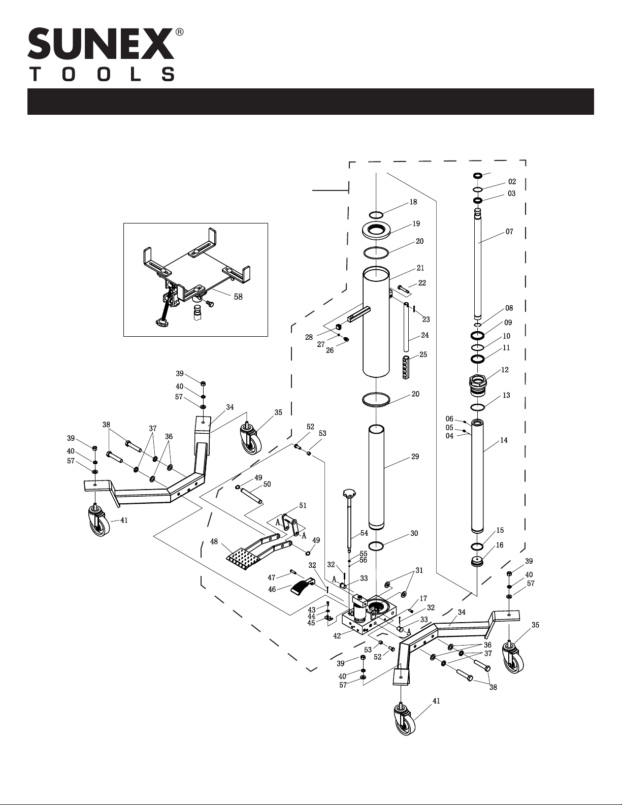
PLEASE REFER TO THE EXPLODED VIEW DRAWING IN THIS MANUAL IN ORDER TO IDENTIFY PARTS.
1. Place hydraulic unit in an upright position and bolt the (2) index #34 leg assemblies to the index #42 pump base using index #38 hex
bolts, index #37 lock washers and index #36 flat washers as shown in the exploded view drawing on page 6.
2. Assemble the (2) index #41 locking caster assemblies and (2) index #35 non-locking casters to the ends of each index #34 leg as shown
in the exploded view drawing, using the index #40 spring washers and index #39 nuts provided.
3. Secure the index #S20 bracket of the complete saddle assembly to the top of the index #7 secondary cylinder plunger with the index
#S19 bolt.
4. Secure the (4) index #S02 fingers to the top of the index #S03 saddle plate using the index #S01 carriage bolts, index #S04 washers and
index #S05 wing nuts as shown in the exploded view drawing on page 7.
5. Secure one end of the index #S28 chain to the index #S03 saddle plate with the index #S29 bolt, index #S27 washers and index #S26
nut as shown in the exploded view drawing.
6. Secure the index #S07 hook seat to the index #S03 saddle plate with the index #S24 washer and index #S25 nut as shown in the
exploded view drawing. Feed the threaded end of the index #S06 hook through the hole in the index #S07 hook seat and secure it
with the index #S08 wing nut.
IMPORTANT! BEFORE USING...
7. Open reservoir vent screw index #26 that is located on the reservoir and below the product label by turning the screw counterclock
wise two (2) full turns. NOTE: JACK WILL NOT OPERATE PROPERLY UNLESS THE VENT SCREW IS OPENED.
If the jack has been used without first opening the reservoir vent screw or the jack has been handled or shipped in different positions,
air may be trapped in the hydraulic system. An air trapped system is identified by insufficient incremental pump strokes and failure to
extend the telescopic rams to maximum height.
FOLLOW THESE INSTRUCTIONS TO PURGE AIR FROM THE SYSTEM:
If the jack is not able to raise the load, raises very slowly, or the second stage will not raise, follow these instructions: (Figure 1 next page)
1. Turn the #3 reservoir vent screw counterclockwise until it stops.
Turn the #1 release valve knob clockwise until it stops.
Pump the #2 foot pedal until both rams are at maximum extension or as high as they can be pumped.
2. Use a 3mm allen wrench to turn the M6x5 screw counterclockwise 1/2 turn.
3. Pump the #2 foot pedal two or three times until the hydraulic fluid escapes from the M6x5 screw hole and there are no air bubbles in
the fluid. On the last pump of the pedal, keep the pedal depressed all the way down and tighten the M6x5 screw.
4. Turn the #1 release valve knob counterclockwise to lower both rams all the way down. Close the release valve knob and pump the
jack to maximum ram extension.
5. Repeat steps 1 through 4 if the condition has not been fully corrected.
If the jack's telescopic rams do not raise or lower smoothly, follow these instructions: (Figure 2 next page)
1. Turn the #3 reservoir vent screw counterclockwise until it stops.
Turn the #1 release valve knob clockwise until it stops.
Pump the #2 foot pedal until both rams are at maximum extension.
2. Use a 4mm allen wrench to turn the M8x10 screw in the primary cylinder nut counterclockwise 1/2 turn.
3. Pump the #2 foot pedal two or three times until the hydraulic fluid escapes from the M8x10 screw hole and there are no air bubbles
in the fluid. Retighten the M8x10 screw.
4. Turn the #1 release valve knob counterclockwise to see if the telescopic rams lower smoothly.
5. Repeat steps 1 through 4 if the condition has not been fully corrected.
Note: If these instructions do not correct the condition, refer to page 4 of this owner's manual on how to check for the correct fluid
level in the jack's reservoir.
OWNER'S MANUAL
7793B Rev. F
CAPACITY: 1/2 TON
TELESCOPIC TRANSMISSION JACK