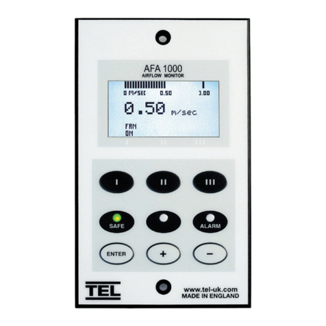
TEL AFA1000/E MK2 Use and care manual

Startup
The AFA1000/E must be eld-calibrated once the
room air supply and exhaust is proportionally
balanced. When the unit is powered up, the
following sequence of events occurs:
1. The alarm performs a self-test of its
functions, LEDs and audible alarm
(approximately 3 seconds).
2. At the end of the delay, the unit will do
one of two things:
a. If the controller has been calibrated, the
unit enters normal operating mode (displays
airow velocity, LED’s and audible alarm
enabled).
b. If the controller has not been calibrated,
the unit will display “ Requires set up, press
Enter to continue”.
Installation &
Calibration Guide
Airow Controls
AFA1000/E MK2
Calibration
1. Press Enter from the “Requires set up” screen or if the controller
is in the Run screen Press and Hold the Enter button for 5 seconds
until the Main Menu is displayed.
2. Using the + / - buttons select SET UP, then select CONFIGURE, then
enter the password (the factory default password is 0-0-0-0), press
Enter to continue.
3. Using the + / - buttons select ECON CONFIGURE, then select
MANUAL / AUTO and press Enter, select MANUAL and press
Enter to continue.
4. Open the sash to the normal operating height and measure the
face velocity using a calibrated instrument. Using the + / - buttons
adjust the Manual output so that the face velocity is equal to the
design velocity, e.g. 0.50m/sec (100fpm) , then press Enter, then
select DONE and press Enter again.
5. Using the + / - buttons select SET UP, then select CALIBRATION,
then enter the password (the factory default password is 0-0-0-0),
press Enter to continue.
6. With the sash open to the normal operating height again measure
the face velocity using a calibrated instrument. Using the + /
-buttons enter the measured face velocity then press Enter, the
controller will then sample the airow for 5 seconds.
7. If the airow sample is unstable the controller will display
“Deviations too High”, follow the instructions to repeat the
sample or quit the calibration.
Temperature Electronics Ltd. Unit 2, Wren Nest Road, Glossop SK13 8HB UK

Installation &
Calibration Guide
Temperature Electronics Ltd. Unit 2, Wren Nest Road, Glossop SK13 8HB UK
8. If the sample is accepted, lower the sash by half and
measure the face velocity using a calibrated instrument.
Using the + / - buttons enter the measured face velocity
and press Enter, the monitor will then sample the airow
for 5 seconds.
9. If the calibration is successful the controller will return the
Main Menu, select RUN to go to normal operating mode
and check the velocity reading is accurate and stable.
10. If the airow sample is unstable the controller will
display “Deviations too High”, follow the instructions to
repeat the sample or quit the calibration.
11. The controller will display “Increase higher airow
sample” if the second sample value is too close to the
rst value entered, close the sash a little and repeat
the higher sample. The minimum dierence between
the samples that the controller will accept is 0.3m/
sec (60fpm).
12. The controller will display “Sensor di too low” if the
controller doesn’t detect any dierence in the sensor
output between the 2 airow samples, check that the
sensor hose is connected and repeat the calibration.
13. If the calibration is stable and accurate Press and
Hold the Enter button for 5 seconds until the Main
Menu is displayed.
14. Using the + / - buttons select SET UP, then select
CONFIGURE, then enter the password (the factory
default password is 0-0-0-0), press Enter to continue.
15. Using the + / - buttons select ECON CONFIGURE, then
select MANUAL / AUTO and press Enter, then select
AUTO and press Enter to continue, then select DONE
and press Enter.
16. The controller will return to the MAIN MENU, select
RUN to go to normal operating mode.
Calibration Tips
1. Ensure that the sensor hose is connected correctly at the
side wall and rear of the sensor.
2. Ensure that the extract fan is running and the Fume
Cupboard is balanced before calibrating the monitor.
3. Take extra time (at least 15 to 20 seconds) to wait for the
airow to settle before capturing the airow samples.
This will minimize the chance of a calibration error due
to turbulence or uctuations.
4. Avoid movement in front of the Fume Cupboard whilst
calibrating the monitor.
5. The Low and High air samples must be at least 0.3m/sec
(60 fpm) apart to calibrate the monitor. This is to avoid
inaccuracy in the calibration sue to insucient dierence
between the samples. The minimum dierence can be
changed in the “Low High di” parameter in the
Cal Cong menu.
6. Do not use fully open and fully closed sash positions for
the calibration points, the recommended positions are
normal operating height (e.g. 500mm 20”) for the rst
sample and approximately half the sash opening (e.g.
250mm 10”) for the second sample.

Installation &
Calibration Guide
Temperature Electronics Ltd. Unit 2, Wren Nest Road, Glossop SK13 8HB UK
Control Settings
The ECON CONFIG menu includes the following control
parameters:-
1. MANUAL / AUTO -- Allows the control output to be set
to Auto or Manual control, manual control is shown
as 0-100% and can be adjusted using the + / - buttons.
In Auto control the output will automatically adjust to
maintain the velocity set point.
2. HIGH SET POINT -- This is used to enter the required face
velocity set point for standard VAV control or the High
set point for dual set point occupancy control.
3. LOW SET POINT -- This is used to enter the required
reduced face velocity set point for dual set point
occupancy control.
4. DAMPER / INVERTER -- This is used to set the output
to 0-10v (direct - for damper) or 10 to 0v (reverse - for
Inverter)
5. MIN OUTPUT -- This is used to set the MIN output
volume when pushbutton III is set to Min/Run/Max
operation.
6. MAX OUTPUT -- This is used to set the MAX output
volume when pushbutton III is set to Min/Run/Max
operation.
7. LOW LIMIT -- This is used to set the fume cupboard
minimum volume when the sash is closed (limits the
damper closed position).
8. HIGH LIMIT -- This is used to set the fume cupboard
maximum volume (limits how far the damper opens).
9. OUTPUT RANGE -- This is used to set the output range to
0-10v (Inverter) or 2-10v (actuator).
10. PROP BAND -- This is the main control parameter
for the VAV control output. If the value is too low the
damper will be unstable and hunt, if the value is too low
the damper will react too slowly. The ideal setting for
this value is to select a value that is as small as possible
but that gives stable control of the damper or Inverter
without ‘hunting’.
11. INTEGRAL TIME -- The Integral Time is the corrective
action of the control output. The PROP BAND control
will result in an oset from the set point, the Integral
will correct the error in small steps over time. The ideal
setting is to select the highest possible value that gives
stable control.
12. INTERAL CUT OFF -- This is a unique parameter that is
used to give a rapid response in control output when
the sash is raised to boost the speed of the output.
The parameter monitors the rate of change of the face
velocity. This parameter should not require changing
from the factory default setting.
13. BOOST DURATION -- The BOOST DURATION is used in
conjunction with a sash position sensor for VAV control.
The controller will drive the output to a pre-determined
position for a brief periof of time before switching back
to face velocity control.

Installation &
Calibration Guide
Connection
Details
Temperature Electronics Ltd. Unit 2, Wren Nest Road, Glossop SK13 8HB UK

Installation &
Calibration Guide
Control Panel Dimensions
Temperature Electronics Ltd. Unit 2, Wren Nest Road, Glossop SK13 8HB UK
Control Panel Cutout Dimensions
(NOT shown to scale)
5.83”
(148mm)
3.46”
(88mm)
1.57”
(40mm)
1.57”
(40mm)
4.65”
(118mm)
3.15”
(80mm)
4.96”
(126mm)
2 xing holes
2.5 mm diameter
for 2 #4 self-
tapping screws,
provided.
0.47”
(12mm)
0.47”
(12mm)
1.45”
(37mm)
1.45”
(37mm)
0.67”
(17mm)
1.45”
(37mm)
2.91”
(74mm)
1.45”
(37mm)
2.91”
(74mm)
SM6 Sensor Dimensions (rear view) SM6 Sensor Dimensions (front view)
0.79”
(20mm)
1.18” (30mm) Dia. Sensor
Hole for Vent Tube
0.157” (4mm)
Tapped
Fixing Hole
0.157” (4mm)
Tapped
Fixing Hole
1”
(25mm)
1”
(25mm)
1.06”
(27mm)
1.06”
(27mm)
0.47” (12mm) Dia.
Hole for SM6 cable
0.39”
(10mm)

Installation &
Calibration Guide
Temperature Electronics Ltd. Unit 2, Wren Nest Road, Glossop SK13 8HB UK
Airow Sensor Installation Diagram
For complete manual and product information, log on to www.tel-uk.com
Table of contents
Other TEL Controllers manuals
Popular Controllers manuals by other brands
WindowMaster
WindowMaster MotorController WCC 310 UL Installation instructions manual
Emerson
Emerson E2 Enhanced RX Technical bulletin
KBR
KBR multimax D6-5 Series user manual
Mitsubishi Electric
Mitsubishi Electric MELSEC iQ-R Series Reference manual
STI
STI Select-Alert STI-SA5000 Series quick start guide
Jula
Jula Anslut 414-110 User instructions
