sunjoe 48000 BTU MAX User manual

© 2021 by Snow Joe®, LLC
All rights reserved. Original instructions. SAVE THESE INSTRUCTIONS
1
A Division of Snow Joe®, LLC Model SJPPH48 Form No. SJ-SJPPH48-880E-M
R
OPERATOR’S MANUAL
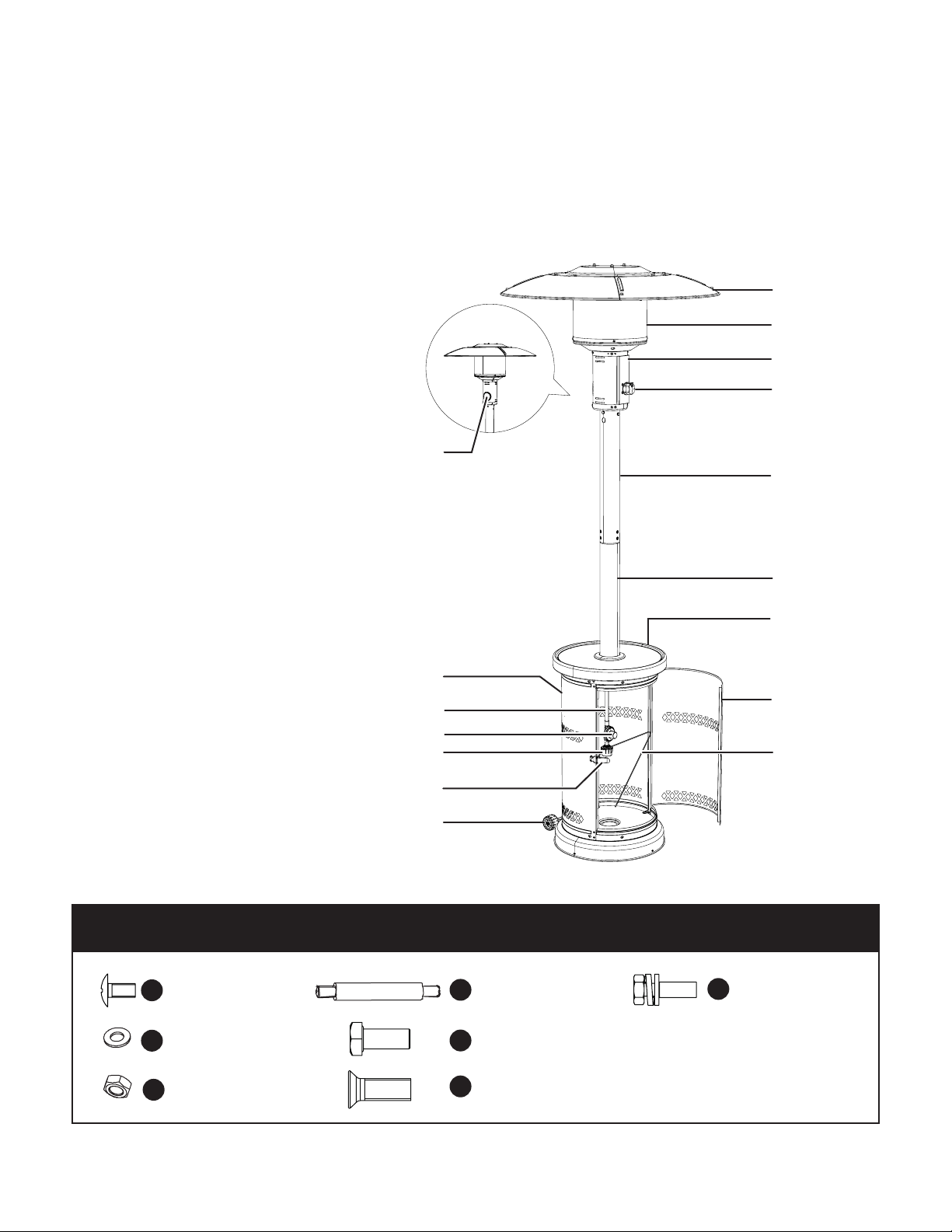
OUTDOOR PROPANE HEATER
48000 BTU MAX | QUICK-START IGNITION
EN
IMPORTANT!
Safety Instructions
All Operators Must Read These
Instructions Before Use
Read all the instructions contained in this manual. Keep this
manual in a safe place, so that the information is available at
all times. If you give this patio heater to another person, make
sure to provide these operating instructions. Basic safety
precautions should always be followed when using the patio
heater.
Notice the personal safety alert symbol mused in this
manual to draw your attention to a WARNING given along
with the particular operating instruction. This means that
the operation requires special ATTENTION, CAUTION, and
AWARENESS.
INSTALLER: Leave this manual with the appliance.
CONSUMER: Retain this manual for future reference.
mFOR OUTDOOR USE ONLY
(outside any enclosure)
mDANGER! CARBON MONOXIDE HAZARD
This appliance can produce carbon monoxide which has no
odor. Using it in an enclosed space can kill you. Never use this
appliance in an enclosed space such as a camper, tent, car or
home.
mWARNING! Improper installation, adjustment,
alteration, service or maintenance can cause property
damage, injury or death. Read the installation, operating
and maintenance instructions thoroughly before installing or
servicing this equipment.
mDANGER! If you smell gas:
1. Shut o gas to the appliance.
2. Extinguish any open ame.
3. If odor continues, keep away from the appliance and
immediately call your gas supplier or re department.
mWARNING! If the information in this manual is
not followed exactly, a re or explosion may result causing
property damage, personal injury, or loss of life.
mWARNING! Do not store or use gasoline or other
ammable vapors and liquids in the vicinity of this or any other
appliance. An LP-cylinder not connected for use shall not be
stored in the vicinity of this or any other appliance.
mWARNING!
1. The installation must conform with local codes or, in the
absence of local codes, with the National Fuel Gas Code,
ANSI Z223.1/NFPA 54, NFPA58 Natural Gas and Propane
Installation Code, CSA B149.1, or Propane Storage and
Handling Code, B149.2
2. The heater, when installed, must be electrically grounded
in accordance with local codes or, in the absence of local
codes, with the National Electrical Code, ANSI/NFPA 70,
or the Canadian Electrical Code, CSA C22.1.
3. Prior to use, check if any part is damaged, such as hoses,
regulators, pilot or burner. If any of the parts are damaged,
do not use the heater. Please contact the Snow Joe®+
Sun Joe®customer service center at 1-866-SNOWJOE
(1-866-766-9563).
4. All leak tests should be done with a soapy solution.
NEVER USE AN OPEN FLAME TO CHECK FOR
LEAKAGE.
5. Children and adults should be alerted to the hazards of
high surface temperatures and should stay away to avoid
burns or clothing ignition.
6. Young children should be carefully supervised when they
are in the area of the heater.
7. Clothing or other ammable materials should not be hung
from the heater, or placed on or near the heater.
8. Any guard or other protective device removed for
servicing the heater must be replaced prior to operating
the heater.
9. Installation and repair should be done by a qualied
service person. The heater should be inspected before
use and at least annually by a qualied service person.
10. Frequently clean this appliance. It is imperative that
the control compartment, burners and circulating air
passageways of the heater be kept clean.
11. Keep the appliance area clear and free from combustible
materials, gasoline and other ammable vapors and
liquids.
12. Do not obstruct the ow of combustion and ventilation air.
13. Keep the ventilation opening(s) of the cylinder enclosure
free and clear from debris.

2
14. This appliance shall be used only in a well ventilated
space and shall not be used in a building, garage or any
other enclosed area.
15. This appliance should be installed with shelter no more
inclusive than:
• With walls on all sides, but with no overhead cover.
• Within a partial enclosure which includes an overhead
cover and no more than two side walls. These side
walls may be parallel, as in a breezeway, or at right
angles to each other.
• Within a partial enclosure which includes an overhead
cover and three side walls, as long as 30 percent
or more of the horizontal periphery of the enclosure is
permanently open.
16. This appliance requires 20 lb (9 kg) LP-gas supply
cylinder. Disconnect the cylinder when the appliance is
not in use.
17. Storage of the appliance indoors is permissible only if the
cylinder is disconnected and removed from the appliance.
18. A cylinder must be stored outdoors in a well ventilated
area out of the reach of children. A disconnected cylinder
must have dust caps tightly installed and must not be
stored in a building, garage or any other enclosed area.
19. Only use this appliance with the equipped pressure
regulator and hose assembly. Replace only with pressure
regulators and hose assemblies with those specied by
the appliance manufacturer.
20. Do not store a spare LP-gas cylinder under or near this
appliance.
21. Never ll the cylinder beyond 80 percent full.
22. Do not clean the heater with cleaners that are combustible
or corrosive.
23. Place the dust cap on the cylinder valve outlet whenever
the cylinder is not in use. Only install the type of dust cap
on the cylinder valve that is provided with the cylinder
valve. Other types of caps or plugs may result in leakage
of propane.
24. Do not use the cylinder tank of this heater for storage.
Certain materials, when stored under the heater, will
be subjected to radiant heat and could be seriously
damaged.
25. Inspect the visible portion of the hose before each use
and inspect the entire hose assembly at least annually.

3
Know Your Outdoor Patio Heater
Read the owner’s manual and safety rules carefully before using your outdoor patio heater. Compare the illustration below to
the actual unit in order to familiarize yourself with the location of the various parts and hardware. Save this manual for future
reference.
Hardware Pack Contents
Phillips Head Bolt
M6x10 | Qty.12
A
Washer
6mm | Qty.18
B
Reector Stud
M6x70 | Qty.3
D
Hexagon Socket Head Bolt
M6x14 | Qty.8
E
Cap Nut
M6 | Qty.15
CPole Screw
M5x12 | Qty.6
F
Wheel Screw
M6x20 | Qty.2
G
1. Heat reector
2. Emitter screen
3. Burner assembly
4. Lighting knob
5. Upper pole
6. Lower pole
7. Bar table
8. Cylinder tank door
9. Cylinder securing wire
10. Wheel assembly
11. Door latch
12. Propane hose connector
13. Propane hose regulator
14. Propane hose
15. Cylinder tank
16. Observation window
1
2
5
BACK
4
6
7
8
9
10
11
12
14
13
15
16
3

4
Technical Data
Heater Fuel Type ....................................... Liquid propane gas
Adjustable Heat Output .................. 25,000 BTU - 48,000 BTU
Coverage Area ...................................... 250 sq. ft. | 9 ft. radius
(23.3 m2| 2.7 m radius)
Runtime Max ............................................... High setting: 4 hrs
50% load per standard 20 lbs tank Low setting: 7 hrs
Dimension ........................................... 32.85 in.(D) x 90.6 in.(H)
(83 cm x 230 cm)
Propane Hose Length .......................................... 4.6 ft (1.4 m)
Injector Diameter ....................................... 0.846 in. (2.15 mm)
Manifold Pressure ................................................... 11 in. W.C.
Max Gas Supply ..................................... 250 PSI (1723.7 kPa)
Min Gas Supply ................................................. 5 PSI (35 kPa)
for Input Adjustment
Net Weight ....................................................... 28.7 lbs (13 kg)
Unpacking
NOTE: Before assembly, make sure that all of the parts and
hardware listed below are present. If any part is missing or
damaged, do not attempt to assemble the product. Contact
the Snow Joe®+ Sun Joe®customer service department at
1-866-SNOWJOE (1-866-766-9563).
Parts
1. Reector center cap 2. Reector panel (4)
3. Burner assembly 4. Upper pole
5. Lower pole 6. Deck ring
7. Cylinder tank 8. Cylinder securing wire
9. Wheel assembly
Hardware
A. M6x10 Phillips head bolt (12)
B. 6 mm plain washer (18)
C. M6 cap nut (15)
D. M6x70 reector stud (3)
E. M6x14 Hexagon socket head bolt (8)
F. M5x12 pole screw (6)
G. M6x20 wheel screw (2)
Assembly
Tools Required (Not included):
• Adjustable open end wrench
• Phillips screwdriver
Choose a soft and level location for assembly. Remove all
parts from the packaging, and check for missing parts.
1. Line up holes on the bracket of the wheel assembly with
the corresponding holes on the base of the cylinder tank,
then insert the M6x20 wheel screws (G) through holes and
tighten to secure. Be sure the wheel assembly is parallel
to the base (Fig. 1).
Hardware Required
2. Place the lower pole in the middle of the bar table, x with
4 M6x14 hexagon socket head bolts (E). Slide the deck
ring down the lower pole to cover the connection part and
the bolts (Fig. 2).
Hardware Required
ITEM DESCRIPTION QTY.
GWheel screw (M6x20) 2
Fig. 1
Wheel assembly
Wheel screw
(M6x20)
Cylinder tank
ITEM DESCRIPTION QTY.
EHexagon socket head bolt (M6x14) 4

5
3. Attach the 4 reector panels together using 4 M6x10
Phillips head bolts (A) and 4 plain washers (B). Secure
with 4 cap nuts (C), as shown (Fig. 3).
Hardware Required
4. Attach the assembled reector panels with the reector
center cap using 8 M6x10 Phillips head bolts (A) and 6
plain washers (B). Secure with 6 cap nuts (C) (Fig. 4).
Hardware Required
5. Attach the 3 reector studs (D) and 3 plain washers (B) to
the top of the burner assembly. Tighten the reector studs
(Fig. 5)
Hardware Required
Fig. 2
Lower pole
Hexagon socket
head bolt
(M6x14)
Deck ring
Slide down
ITEM DESCRIPTION QTY.
APhillips head bolt (M6x10) 4
BPlain Washers (6 mm) 4
CCap nut (M6) 4
Fig. 3 Reector panels
Phillips head bolt (M6x10)
Plain
washer Cap nut
ITEM DESCRIPTION QTY.
APhillips head bolt (M6x10) 8
BPlain Washer (6 mm) 8
CCap nut (M6) 8
Assembled
reector panels
Fig. 4 Reector center cap
Phillips head bolt (M6x10)
Cap nut Plain washer
ITEM DESCRIPTION QTY.
DReector stud (M6x70) 3
BPlain Washer (6 mm) 3
Fig. 5
Reector stud
Plain washer
Burner
assembly

6
6. Attach the reector assembly to the burner assembly.
Place a plain washer (B) over the threaded end of each
reector stud (D) sticking out through reector assembly
and secure with cap nuts (C). Note: Do not overtighten
(Fig. 6).
Hardware Required
7. Insert the propane hose that is connected with the burner
assembly into the upper pole. Secure with 4 M6x14
hexagon socket head bolts (E) (Fig. 7)
Hardware Required
8. Connect the upper pole assembly with the lower pole
assembly as shown. Fix with 6 M5x12 pole screws (F)
(Fig. 8).
Hardware Required
9. Fill sand into the cylinder tank base through the hole in the
middle, as shown (Fig. 9).
NOTE: Purchase sand separately at your local garden
center or hardware store.
10. Insert the ends of the cylinder securing wire into the two
small holes on the tank base (Fig. 10).
ITEM DESCRIPTION QTY.
CCap nut (M6) 3
BPlain Washer (6 mm) 3
Fig. 6
Reector
assembly Plain washer
Burner
assembly
Cap nut
Reector stud
ITEM DESCRIPTION QTY.
EHexagon socket head bolt (M6x14) 4
Fig. 7
Hexagon socket
head bolt
(M6x14)
Burner
assembly
Propane
hose
Upper
pole
ITEM DESCRIPTION QTY.
FPole screw (M5x12) 6
Fig. 8
Upper pole
assembly
Lower pole
assembly
Pole screw
(M5x12)
Fig. 9
Fill the hole
with sand
until it's full.

7
Using the Propane Tank
This appliance requires 20 lbs (9 kg) LP-gas supply cylinder.
(not included). Propane is highly ammable and may
ignite unexpectedly when mixed with air. Follow the safety
instructions below when handling the propane cylinder:
• The cylinder used with this heater must be constructed and
marked in accordance with the Specications for LP-gas
cylinders of the U.S. Department of Transportation (DOT);
or the Standard for Cylinders, Spheres and Tubes for
Transportation of Dangerous Goods and Commission, CAN/
CSA-B339, as applicable;
• The cylinder used with this heater must be provided with
a listed overlling prevention device; and provided with a
cylinder connection device compatible with the connection
for the appliance;
• Keeping the ventilation opening(s) of the cylinder enclosure
free and clear from debris;
• Do not store a spare LP-gas cylinder under or near this
appliance;
• Never ll the cylinder beyond 80 percent full;
• Place the dust cap on the cylinder valve outlet whenever
the cylinder is not in use. Only install the type of dust cap
on the cylinder valve that is provided with the cylinder
valve. Other types of caps or plugs may result in leakage of
propane.
mWARNING! A dented, rusted or damaged
propane cylinder may be hazardous and should be checked
by your propane supplier. Never use a propane cylinder with a
damaged valve connection.
Connect the Propane Tank
mWARNING! Never connect an unregulated
propane cylinder to the heater.
1. Open the tank door and place a cylinder inside the tank.
Let it sit in securely. Use the securing wire to secure the
gas cylinder, like shown (Fig. 11).
2. Connect the propane hose connector with the propane
cylinder. Turn clockwise to secure (Fig. 12).
3. Close the tank door. Lock the door latch
Leakage Test
All connections of this patio heater have been checked at the
factory for leakage. However, in transportation and handling
some connections may have loosened. It's recommended to
run the leakage test every time before using and after parts
replacement.
mWARNING!
• Do not use an open ame to check for leakage.
• Do not smoke during testing.
• Do not test indoors.
• A leak check must be performed whenever the propane
cylinder is replaced.
NOTE: Use only the pressure regulator supplied with this patio
hearer. Replace it with those specied by the manufacturer
only.
Fig. 10
Cylinder
securing wire
Insert in the
small holes
Fig. 11
Propane
cylinder
Cylinder
securing wire
Tank door
Fig. 12
Propane
hose
Propane
hose
connector

8
1. Make leakage solution by mixing 1 part liquid dish soap
and 3 parts water.
2. With the cylinder connected to the hose, spoon or brush
several drops (or use squirt bottle) of the solution onto the
connections along the hose, regulator and cylinder
(Fig. 13).
3. Open the propane cylinder valve. Inspect the connections
and look for bubbles.
4. If no bubbles appear, the connection is safe. If bubbles
appear, there is leakage. Loosen and re-tighten this
connection. If there is still a leak, turn o the cylinder
and contact the Snow Joe®+ Sun Joe®customer service
center at 1-866-SNOWJOE (1-866-766-9563).
At least once a year, a complete inspection of the entire gas
path components should be performed by a professional
technician.
Operation
mWARNING! Do not attempt to operate the heater
until you have read and understand all precautions in this
manual. Make sure all assembly is complete and leakage test
have been performed. Failure to do so can result in death,
serious personal injury, or property damage.
Before Turning on the Gas Supply
1. The heater is designed and approved for OUTDOOR USE
ONLY. DO NOT use it inside a building, garage, or any
other enclosed area.
2. Make sure the surrounding areas are free of combustible
materials, gasoline, and other ammable vapors or liquids.
3. Ensure that there is no obstruction of air ventilation.
Ensure all gas connections are tight and there's no leak.
4. Be sure any component removed during assembly or
servicing is replaced and fastened prior to starting.
Lighting the Heater
mWARNING!
• Heater should be thoroughly inspected before each use,
and by a qualied service person at least annually. If
relighting a hot heater, always wait at least 5 minutes.
• Before lighting, inspect the hose assembly for evidence of
excessive abrasion, cuts, or wear. Suspected areas should
be leak tested. If the hose leaks, it must be replaced prior
to operation. Only use the replacement hose assembly
specied by manufacturer.
mWARNING! Follow the instruction below to light
the heater. Improper lighting operation may cause personal
injury or property damage.
1. Connect the propane cylinder and perform the leakage
test as instructed above.
2. Make sure the lighting knob is in the OFF position
(pointing to the black dot). Open the propane cylinder
valve.
3. Push in the lighting knob and turn it counterclockwise to
the LOW position (pointing to the small red dot). This will
light the burner. If needed, keep depressing and turning
the lighting knob counterclockwise until the burner is lit.
You will hear one click when the burner is lit (Fig. 14).
4. Once the burner is lit, keep the knob depressed for 30
seconds. Then release the lighting knob.
5. If burner does not stay lit, repeat steps 3 and 4 after 5
minutes.
6. If burner still does not stay lit, then:
i. Push in the lighting knob and turn it counterclockwise to
the "LOW" position.
ii. Keep depressing the lighting knob, use a long stem
lighter to light the burner through the ignition hole on
the emitter screen (Fig. 15).
Fig. 13
Fig. 14
OFF LOW HIGH
Lighting knob

9
iii. Repeat step 4.
7. After the burner is lit, adjust the temperature by rotating
the lighting knob. Turn the lighting knob counterclockwise
to "HIGH" position (pointing to the big red dot). If you want
a lower temperature, turn the control knob clockwise to
the "LOW" position (pointing to the small red dot) (Fig. 14).
mWARNING! FOR YOUR SAFETY
If at any time you are unable to light burner and smell gas, wait
at least 5 minutes to allow gas to dissipate before attempting
to light the gas appliance again.
Flame Characteristic
The ame can be checked through the emitter screen during
operation. The normal ame should be mostly blue with yellow
tip. Abnormal ame characteristics include:
• The ame extends beyond the emitter screen.
• Black spots can be seen accumulating on the emitter
screen or the reector assembly.
If any of the above situations appears, turn o the heater
immediately and contact the Snow Joe®+ Sun Joe®customer
service department at 1-866-SNOWJOE (1-866-766-9563).
The heater should not be used again before it's serviced or
repaired.
Operation Tips
mWARNING! When use the heater for the rst
time, avoid inhaling fumes emitted from the heater. The fumes
contain smoke and odor from the burning of oils used in
manufacturing. The fumes will dissipate after approximately 30
minutes. The heater should NOT produce thick black smoke.
mWARNING! Do not touch or move the heater for
at least 45 minutes after use. Allow the heater to cool down
completely.
mCAUTION! Items above, beside or under this
heater while in use will be subject to radiant heat and could be
seriously damaged.
mWARNING! This heater must be placed on level,
rm ground.
mWARNING! Never operate in an explosive
atmosphere. Keep away from areas where gasoline or other
ammable liquids or vapors are stored or used.
• This heater is designed for the heating of outdoor patios,
decks, spas, pools and open work areas. Always make
sure that adequate fresh air ventilation is provided. Follow
the spacing tolerances shown in the following gure at all
times (Fig 16).
• When initially turned on, it's normal for the heater to
produce some noise. If this happens, turn the lighting
knob to the LOW position (pointing to the small red dot).
Wait for a while and then adjust the knob to the desired
temperature.
• When the heater is on, the emitter screen will become
bright red due to the intense heat. The blue ame can be
seen through the emitter screen.
• If the ame appears to be mostly yellow or there's heavy
black smoke produced by the heater, there may be an
obstruction of airow. If this happens, turn o the heater
and contact the Snow Joe®+ Sun Joe®customer service
department at 1-866-SNOWJOE (1-866-766-9563).
• If the ame appears to be very small, this may be caused
by the insucient pressure. Change or rell the propane
cylinder.
• If the heater extinguished accidentally, rotate the lighting
knob to the OFF position (pointing to the black dot), wait
for 5 minutes and follow the instruction in Lighting the
Heater section from step 2 to relight the heater.
NOTE: Always wait for 5 minutes before relighting.
Extinguishing
1. Push in and turn the lighting knob counterclockwise to
OFF position (pointing to the black dot) (Fig. 14).
2. Close the propane cylinder valve when appliance is not
in use. Disconnect and remove the cylinder if the heater
needs to be transported or stored.
Fig. 15
Emitter
screen
Ignition
hole
91 cm
61 cm
61 cm
Fig. 16

10
NOTE: After use, it's normal for the emitter screen to have
some discoloration.
mWARNING! Gas appliance will be hot after
use. DO NOT touch or move gas appliance for at least 45
minutes after use.
In The Event of Gas Leakage:
1. Turn the lighting knob to OFF position.
2. Close the propane cylinder valve.
3. Wait at least 5 minutes to allow gas to dissipate.
4. If odor continues, immediately call gas supplier.
Maintenance
To enjoy years of outstanding performance from the patio
heater, make sure you perform the following maintenance
activities on a regular basis.
mWARNING! DO NOT touch or move gas appliance
for at least 45 minutes after use. Allow it to cool before
touching.
Cleaning
This patio heater should be cleaned on a regular basis to
promote safer experiences and longer product life.
DO NOT attempt to clean this heater until it is COMPLETELY
extinguished and COMPLETELY cooled down.
1. Keep exterior surfaces clean.
2. Use warm soapy water for cleaning. Never use a
ammable or corrosive cleaning agent.
3. While cleaning your unit, be sure to keep the area around
the heater dry at all times. If any part of the gas control
system is exposed to water in any way, do NOT use it. It
must be replaced.
General Maintenance
1. Keep the work area free and clean from combustible
materials, gasoline and other ammable vapors and
liquids. Do not obstruct the ow of combustion and
ventilation air. Keep the ventilation opening(s) of the
cylinder enclosure free and clear from debris.
2. Turn on the heater as instructed before, and visually check
burner ames. The ames should be primarily blue with
yellow tip.
3. Remove the Hexagon socket head bolts (M6x14) used
to secure the burner assembly and the upper pole. Take
out the burner assembly and check if there are cracks
or worn sections on the propane hose. If yes, do not use
the heater and contact Snow Joe®+ Sun Joe®customer
service at 1-866-SNOWJOE (1-866-766-9563) for
assistance.
NOTE: If used in a salt-air environment (such as near an
ocean), corrosion occurs faster than normal. Frequently
check for corroded areas and repair them promptly.
4. Spiders and insects tend to nest inside the heater. This
can cause damage to the heater and render it unsafe to
use. At least once a year, the unit should be inspected for
the presence of spiders, spider webs or other insects.
5. Air ow must be unobstructed. Keep controls, burner,
and circulating air passageways clean. Signs of possible
blockage include:
i). Gas odor with extreme yellow ame.
ii). Heater does NOT reach the desired temperature.
iii). Heater glow is excessively uneven.
iv). Heater makes popping noises.
6. Carbon deposits may create a re hazard. Clean the
reector and the emitter screen with warm soapy water if
any carbon deposits is seen.
Annual Propane Hose Leakage Test
All connections on the patio heater have been adjusted and
tightened at the factory, however, in case any connection is
loosened during long term use, it's recommended that users
test the propane hose connection at least once a year.
mWARNING!
• Do not use an open ame to check for leakage.
• Do not smoke during testing.
• Do not test indoors.
1. Make leakage solution by mixing 1 part liquid dish soap
and 3 parts water.
2. With the cylinder connected to the hose, remove the
observation window panel located opposite to the lighting
knob (Fig. 18).
Fig. 17
Burner assembly
Upper pole
Check for cracks or
worn parts

11
3. Through the observation window, spoon or brush several
drops (or use squirt bottle) of the solution onto the
automatic valve connection and the injector connection.
(Fig. 18).
4. Through one of the holes on the upper pole, spoon, squirt
or brush several drops of the solution onto the propane
hose connection (Fig. 19).
5. Open the gas cylinder valve. Inspect the connections and
look for bubbles.
6. If no bubbles appear, the connection is safe. If bubbles
appear, there is leakage. Loosen and re-tighten this
connection. If there is still a leak, turn o the cylinder
and contact the Snow Joe®+ Sun Joe®customer service
center at 1-866-SNOWJOE (1-866-766-9563).
Transport and Storage
DO NOT move or store this heater until it is COMPLETELY
extinguished and cooled down.
Between Uses:
1. Turn the lighting knob to "OFF" position.
2. Close the propane cylinder valve.
3. Store the heater upright in an area sheltered from direct
contact with inclement weather (such as rain, sleet, hail,
snow, dust and debris).
4. If desired, cover the heater to protect exterior surfaces
and to help prevent build up in air passages.
NOTE: Wait until heater is cool before covering.
Transporting:
1. Turn the lighting knob to "OFF" position. Close the
propane cylinder valve.
2. Disconnect the propane hose from the cylinder by turning
the connector counterclockwise. Remove the propane
cylinder from the tank.
3. Wait until heater is completely cooled down before
moving.
4. Before using the heater in the new location, connect
the propane cylinder and perform the leakage test as
instructed before.
Long-term storage:
1. Turn the lighting knob to "OFF" position. Close the
propane cylinder valve.
2. Disconnect the propane hose from the cylinder by turning
the connector counterclockwise. Remove the propane
cylinder from the tank. Store the cylinder in a secure, well-
ventilated location outdoors. DO NOT store in a location
where the temperature will exceed 125 ºF.
3. Store heater upright in an area sheltered from direct
contact with inclement weather (such as rain, sleet, hail,
snow, dust and debris).
4. If desired, cover the heater to protect exterior surfaces
and to help prevent build up of dust in air passages.
NOTE: Wait until heater is cool before covering.
Support
If your Sun Joe®SJPPH48 outdoor patio heater requires
service or maintenance, please call 1-866-SNOWJOE
(1-866-766-9563) for assistance.
Model and Serial Numbers
When contacting the company, reordering parts, or arranging
service from an authorized dealer, you will need to provide
the model and serial numbers, which can be found on the
decal located on the unit. Copy these numbers into the space
provided below.
Fig. 18
Observation
window panel
Injector
connection
Automatic valve
connection
Fig. 19
Propane hose
connection
Spoon, squirt
or brush the
solution through
the hole
Record the following numbers from your new product:
Model #:
Serial #:
S J P P H 4 8 -

12
Troubleshooting
mWARNING! Always turn the patio heater o and remove the cylinder before performing any adjustments, maintenance,
or repairs. For any problems/situation unseen in the manual, please contact the Snow Joe®+ Sun Joe®customer service
department at 1-866-SNOWJOE (1-866-766-9563).
The heater
cannot be
ignited
Problem Possible Cause Solution
1. Replace or rell the cylinder.
2. Push and turn on the lighting knob as instructed in
the manual.
3. Contact Snow Joe®+ Sun Joe®customer service
center at 1-866-SNOWJOE (1-866-766-9563).
Ignition will not
stay on
Thermocouple is broken. Contact Snow Joe®+ Sun Joe®customer service
center at 1-866-SNOWJOE (1-866-766-9563).
No click sound
while rotating the
lighting knob
1. Ignitor pin is broken.
2. The lighting knob is broken.
1. Cylinder pressure is low.
2. Lighting knob is in OFF position.
3. Thermocouple is broken.
Contact Snow Joe®+ Sun Joe®customer service
center at 1-866-SNOWJOE (1-866-766-9563).

13
Optional Accessories
mWARNING! ALWAYS use only authorized Snow Joe®+ Sun Joe®replacement parts and accessories. NEVER use
replacement parts or accessories that are not intended for use with this patio heater. Contact Snow Joe®+ Sun Joe®if you
are unsure whether it is safe to use a particular replacement part or accessory with your patio heater. The use of any other
attachment or accessory can be dangerous and could cause injury or mechanical damage.
NOTE: Accessories are subject to change without any obligation on the part of Snow Joe®+ Sun Joe®to provide notice of such
changes. Accessories can be ordered online at sunjoe.com or via phone by contacting the Snow Joe®+ Sun Joe®customer
service center at 1-866-SNOWJOE (1-866-766-9563).
SJPPH48 Patio Heater Hardware Pack
SJPPH48 Patio Heater Propane Hose
SJPPH48-BRZ-HP
SJPPH48-SS-HP
SJPPH48-SLV-HP
SJPPH48-HOSE
ModelAccessories Item
1
2

14
SNOW JOE®+ SUN JOE®CUSTOMER PROMISE
OUR WARRANTY:
Snow Joe warrants new, genuine, powered and non-powered Products to be free from defects in material or workmanship when used
for ordinary household use for a period of two years from the date of purchase by the original, end-user purchaser when purchased
from Snow Joe or from one of Snow Joe’s authorized sellers with proof of purchase. Because Snow Joe is unable to control the quality
of its Products sold by unauthorized sellers, unless otherwise prohibited by law, this Warranty does not cover Products purchased from
unauthorized sellers. If your Product does not work or there’s an issue with a specic part that is covered by the terms of this Warranty,
Snow Joe will elect to either (1) send you a free replacement part, (2) replace the Product with a new or comparable product at no
charge, (3) repair the Product, or (4) refund the full purchase price of the Product to the original purchaser and owner. How cool is that!
This Warranty gives you specific legal rights, and you may also have other rights which vary from State to State.
PRODUCT REGISTRATION:
Snow Joe strongly encourages you to register your Product. You can register online at snowjoe.com/register, or by printing and
mailing in a registration card available online from our website, or calling our Customer Service Department at 1-866-SNOWJOE
(1-866-766-9563), or by e-mailing us at [email protected]. Failure to register your Product will not diminish your warranty
rights. However, registering your Product will allow Snow Joe to better serve you with any of your customer service needs.
WHO CAN SEEK LIMITED WARRANTY COVERAGE:
This Warranty is extended by Snow Joe to the original purchaser and original owner of the Product.
WHAT IS NOT COVERED?
This Warranty does not apply if the Product has been used commercially or for non-household or rental applications. This Warranty also
does not apply if the Product was purchased from an unauthorized seller. This Warranty also does not cover cosmetic changes that do
not aect performance. Wearing parts like belts, augers, chains and tines are not covered under this Warranty, and can be purchased
at snowjoe.com or by calling 1-866-SNOWJOE (1-866-766-9563).
ABOVE ALL ELSE, Snow Joe, LLC (“Snow Joe”) is dedicated to you, our customer. We strive to make your experience as pleasant as
possible. Unfortunately, there are times when a Snow Joe®, Sun Joe®, or Aqua Joe®product (“Product”) does not work or breaks under
normal operating conditions. We think it’s important that you know what you can expect from us. That’s why we have a Limited Warranty
(“Warranty”) for our Products.
EN


16
EN
©2021 Snow Joe®, LLC
Derechos reservados. Instrucciones originales. GUARDE ESTAS INSTRUCCIONES
Una división de Snow Joe®, LLC Modelo SJPPH48 Forma N° SJ-SJPPH48-880S-M
R
MANUAL DEL OPERADOR
CALENTADOR A GAS PROPANO
DE EXTERIORES PARA PATIOS
48,000 BTU MÁX. | ENCENDIDO RÁPIDO
SP
¡IMPORTANTE!
Instrucciones de seguridad
Todos los operadores deberán leer
estas instrucciones antes del uso
Lea todas las instrucciones contenidas en este manual.
Conserve este manual en un lugar seguro de manera que
la información esté disponible siempre. Si le entrega este
calentador de patio a otra persona, asegúrese de entregarle
también instrucciones de operación. Se deben tomar siempre
precauciones básicas de seguridad al usar este calentador de
patio.
Preste atención al símbolo mde alerta de seguridad
personal usado en este manual para enfocar su atención a
una ADVERTENCIA dada junto a la instrucción de operación
particular. Esto signica que la operación requiere ATENCIÓN,
PRECAUCIÓN y CAUTELA especiales.
AL INSTALADOR: deje este manual con el artefacto.
AL CONSUMIDOR: conserve este manual para futuras
referencias.
m SOLO PARA USO EN
EXTERIORES (fuera de cualquier
lugar cerrado)
m¡PELIGRO! MONÓXIDO DE CARBONO
Este artefacto puede producir monóxido de carbono, el cual
es inodoro. Usarlo en un espacio cerrado puede matarle.
Nunca use este artefacto en un espacio cerrado tal como un
camper, carpa, auto o vivienda.
m¡ADVERTENCIA! Una instalación, ajuste,
alteración, servicio o mantenimiento inadecuados pueden
causar daños materiales, lesiones personales o muerte.
Lea a fondo las instrucciones de instalación, operación y
mantenimiento antes de instalar o reparar este dispositivo.
m ¡PELIGRO! Si usted percibe un olor a gas:
1. Cierre el ujo de gas al artefacto.
2. Extinga cualquier fuego abierto.
3. Si el olor sigue, aléjese del artefacto y llame
inmediatamente a su proveedor de gas o a los bomberos.
m¡ADVERTENCIA! Si no se obedecen al pie
de la letra las instrucciones de este manual, puede ocurrir una
explosión que cause daños materiales, lesiones personales, o
la muerte.
m¡ADVERTENCIA! No almacene o use gasolina
ni otros vapores o líquidos inamables en las proximidades
de este o cualquier otro artefacto. Un cilindro de gas propano
desconectado no deberá ser guardado en las proximidades de
este o de ningún otro artefacto.
m¡ADVERTENCIA!
1. La instalación debe cumplir con los códigos locales o, en
ausencia de códigos locales, el Código Nacional de Gas
de Combustible (National Fuel Gas Code) ANSI Z223.1/
NPFA 54, el Código de Instalación de Gas Natural y Gas
Propano (Natural Gas and Propane Installation Code)
NFPA58, CSA B149.1, o el Código de Almacenamiento
y Manipulación de Gas Propano (Propane Storage and
Handling Code) B149.2.
2. El calentador, al ser instalado, debe estar eléctricamente
conectado a tierra según los códigos locales o, en
ausencia de códigos locales, según el Código Eléctrico
Nacional (National Electrical Code) ANSI/NFPA 70 o el
Código Eléctrico Canadiense (Canadian Electrical Code)
CSA C22.1.
3. Antes de su uso, compruebe si alguna parte del
calentador está dañada, tal como una manguera,
regulador, piloto o quemador. Si alguna parte está
dañada, no use el calentador. Comuníquese con la central
de servicio al cliente Snow Joe®+ Sun Joe®llamando al
1-866-SNOWJOE (1-866-766-9563).
4. Todas las pruebas de fugas deben ser hechas con una
solución jabonosa. NUNCA USE UNA LLAMA ABIERTA
PARA INSPECCIONAR SI HAY FUGAS.
5. Los niños y adultos deben ser alertados de los peligros
de las elevadas temperaturas de supercie, y deben estar
alejados para evitar quemaduras o encendido de ropas.
6. Los niños pequeños deben ser supervisados
cuidadosamente cuando estén en el área del calentador.
7. La ropa u otros materiales inamables no deben ser
colgados del calentador, ni colocados sobre o cerca del
calentador.
8. Cualquier guarda o dispositivo de protección retirado
para la reparación del calentador deberá ser colocado de
vuelta antes de volver a operar el calentador.

17
9. La instalación y reparación deberán ser hechas por un
técnico de servicio calicado. El calentador debe ser
inspeccionado antes de su uso y al menos una vez al año
por un técnico de servicio calicado.
10. Limpie con frecuencia este artefacto. Es imperativo que el
compartimiento de control, los quemadores y conductos
de circulación de aire del calentador estén limpios en todo
momento.
11. Mantenga el área del artefacto despejada y libre de
materiales combustibles tales como gasolina y otros
vapores y líquidos inamables.
12. No obstruya el ujo de aire de combustión y de
ventilación.
13. Mantenga libres de residuos las aberturas de ventilación
del compartimiento del cilindro.
14. Este artefacto solo deberá ser usado en un espacio bien
ventilado, y no deberá ser usado dentro de un edicio,
garaje ni ninguna otra área cerrada.
15. Este artefacto deberá ser instalado en un alojamiento no
más inclusivo que:
• Con paredes en todos los lados, pero sin techo.
• Dentro de un alojamiento parcial que incluya un techo
pero no más de dos paredes laterales. Estas paredes
laterales pueden ser paralelas, como en un pasillo
techado, o en ángulo recto una con otra.
• Dentro de un alojamiento parcial que incluya un techo
y tres paredes laterales, siempre y cuando el 30%
o más de la periferia horizontal del alojamiento esté
permanentemente abierto.
16. Este artefacto requiere el suministro de gas licuado
propano de un cilindro de 9 kg (20 lb). Desconecte el
cilindro cuando el artefacto no esté siendo usado.
17. El almacenamiento del artefacto en interiores es permitido
solo si el cilindro de gas es desconectado y retirado del
artefacto.
18. Un cilindro de gas debe ser guardado en exteriores, en
un área bien ventilada, lejos del alcance de los niños.
Un cilindro de gas desconectado debe tener tapas
guardapolvos rmemente instaladas y no debe ser
guardado dentro de un edicio, garaje ni ningún otro
espacio cerrado.
19. Solo use este artefacto con el regulador de presión y
ensamblado de manguera incluidos. Reemplácelos solo
con un regulador de presión y ensamblado de manguera
especicados por el fabricante del artefacto.
20. No guarde un cilindro de gas licuado extra debajo o cerca
de este artefacto.
21. Nunca llene el cilindro más de un 80% de su capacidad.
22. No limpie el calentador con limpiadores combustibles o
corrosivos.
23. Coloque la tapa guardapolvos en la válvula saliente del
cilindro siempre que el cilindro de gas no esté en uso.
Solo instale una tapa guardapolvo en la válvula del cilindro
igual a la que se suministra con dicha válvula. Otros tipos
de tapas o tapones pueden causar fugas del gas propano.
24. No use el compartimiento de cilindro de este calentador
para guardar materiales. Algunos materiales, al ser
guardados debajo del calentador, estarán sujetos a calor
radiante y pueden ser severamente dañados.
25. Inspeccione la parte visible de la manguera antes de cada
uso, e inspeccione todo el ensamblado de manguera al
menos una vez al año.

18
Conozca su calentador de exteriores para patios
Lea detenidamente este manual del propietario y el reglamento de seguridad antes de usar su calentador de exteriores para
patios. Compare la ilustración debajo con la unidad real para familiarizarse con la ubicación de las diversas partes y accesorios
de ensamblado. Conserve este manual para futuras referencias.
Contenido de paquete de accesorios de ensamblado
Perno Phillips
M6x30 | 12 unidades
A
Arandela
6 mm | 18 unidades
B
Clavija de reector
M6x70 | 3 unidades
D
Perno hueco hexagonal
M6x14 | 8 unidades
E
Tuerca ciega
M6 | 15 unidades
CTornillo de poste
M5x12 | 6 unidades
F
Tornillo de rueda
M6x20 | 2 unidades
G
1. Reector de calor
2. Pantalla emisora
3. Estructura de quemador
4. Perilla de encendido
5. Poste superior
6. Poste inferior
7. Mesa de barra
8. Puerta de compartimiento de
cilindro
9. Alambre sujetador de cilindro
10. Ensamblado de ruedas
11. Pestillo de puerta
12. Conector de gas propano
13. Regulador de manguera de gas
propano
14. Manguera de gas propano
15. Compartimiento de cilindro
16. Ventana de observación
1
2
5
REVERSO
4
6
7
8
9
10
11
12
14
13
15
16
3

19
Datos técnicos
Tipo de combustible ............................... Gas licuado propano
Salida de calor ajustable .......... De 25,000 BTU a 48,000 BTU
Área de cobertura ............................ 250 pie2| Radio de 9 pies
(23.3 m2| Radio de 2.7 m)
Tiempo máx. de funcionamiento .................... Modo alto: 4 hrs
50% de carga por tanque estándar de 20 lb. Modo bajo: 7 hrs
Dimensiones ................ 32.85 plg (diámetro) × 90.6 plg (altura)
(83 cm × 230 cm)
Longitud de manguera de gas propano .......... 4.6 pies (1.4 m)
Diámetro de inyector ................................ 0.846 plg (2.15 mm)
Presión de colector ....................................................... 11 WC
Suministro máximo de gas .................... 250 PSI (1,723.7 kPa)
Suministro mínimo de gas ................................. 5 PSI (35 kPa)
para ajuste de entrada
Peso neto .......................................................... 28.7 lb (13 kg)
Desembalaje
NOTA: antes de empezar a ensamblar este producto,
asegúrese de que todas las partes y accesorios de
ensamblado mostrados a continuación estén presentes. Si
cualquier parte falta o está dañada, no intente ensamblar el
producto. Comuníquese con la central de servicio al cliente
Snow Joe®+ Sun Joe®llamando al 1-866-SNOWJOE
(1-866-766-9563).
Partes
1. Tapa reectora de centro 2. Panel reector (×4)
3. Estructura de quemador 4. Poste superior
5. Poste inferior 6. Aro de plataforma
7. Compartimiento 8. Alambre sujetador de cilindro
de cilindro
9. Ensamblado de ruedas
Accesorios de ensamblado
A. Perno Phillips M6x10 (×12)
B. Arandela plana de 6 mm (×18)
C. Tuerca ciega M6 (×15)
D. Clavija de reector M6x70 (×3)
E. Perno hueco hexagonal M6x14 (×8)
F. Tornillo de poste M5x12 (×6)
G. Tornillo de rueda M6x20 (×2)
Ensamblado
Herramientas requeridas (no incluidas):
• Llave de tuercas ajustable
• Destornillador Phillips
Seleccione un lugar suave y nivelado para el ensamblado.
Retire todas las partes del empacado y compruebe que no
haya partes faltantes.
1. Alinee los oricios en el soporte del ensamblado de
ruedas con los oricios correspondientes en la base del
compartimiento de cilindro, luego inserte los tornillos de
rueda M6x20 (G) a través de los oricios y apriete para
asegurar. Asegúrese de que el ensamblado de ruedas sea
paralelo a la base (Fig. 1).
Accesorios de ensamblado requeridos
2. Coloque el poste inferior en medio de la mesa de barra, y
fíjelo con cuatro pernos huecos hexagonales M6x14 (E).
Deslice el anillo de plataforma en el poste inferior para
cubrir la conexión y los pernos huecos hexagonales
(Fig. 2).
Accesorios de ensamblado requeridos
ARTÍCULO DESCRIPCIÓN CANT.
GTornillo de rueda (M6x20) 2
Fig. 1
Ensamblado de
ruedas
Tornillo de
rueda (M6x20)
Compartimiento
de cilindro
ARTÍCULO DESCRIPCIÓN CANT.
EPerno hueco hexagonal (M6x14) 4

20
3. Conecte los cuatro paneles de reector usando cuatro
pernos Phillips M6x10 (A) y cuatro arandelas planas (B).
Asegure con cuatro tuercas ciegas (C), tal como se
muestra (Fig. 3).
Accesorios de ensamblado requeridos
4. Conecte los paneles de reector ensamblados con la tapa
central de reector usando ocho pernos Phillips M6x10
(A) y seis arandelas planas (B). Asegure con seis tuercas
ciegas (C), tal como se muestra (Fig. 4).
Accesorios de ensamblado requeridos
5. Conecte las tres clavijas de reector (D) y las tres
arandelas planas (B) a la parte superior de la estructura de
quemador. Apriete las clavijas de reector (Fig. 5)
Accesorios de ensamblado requeridos
6. Conecte el ensamblado de reector a la estructura de
quemador. Coloque una arandela plana (B) sobre el
extremo enroscado de cada clavija de reector (D) que
sobresalga del ensamblado de reector, y asegúrela con
una tuerca ciega (C). Nota: no sobreajuste (Fig. 6).
Fig. 2
Poste inferior
Perno hueco
hexagonal
(M6x14)
Aro de plataforma
Deslice
hacia abajo
Fig. 2
Poste inferior
Perno hueco
hexagonal
(M6x14)
Aro de plataforma
Deslice
hacia abajo
ARTÍCULO DESCRIPCIÓN CANT.
APerno Phillips (M6x10) 4
BArandela plana (6 mm) 4
CTuerca ciega (M6) 4
Fig. 3 Paneles de
reector
Perno Phillips (M6x10)
Arandela
plana
Tuerca ciega
ARTÍCULO DESCRIPCIÓN CANT.
APerno Phillips (M6x10) 8
BArandela plana (6 mm) 8
CTuerca ciega (M6) 8
Paneles
ensamblados de
reector
Fig. 4 Tapa central
de reector
Perno Phillips (M6x10)
Tuerca
ciega Arandela plana
ARTÍCULO DESCRIPCIÓN CANT.
DClavija de reector (M6x70) 3
BArandela plana (6 mm) 3
Fig. 5
Clavija de
reector
Arandela plana
Estructura de
quemador
This manual suits for next models
1
Table of contents
Languages: