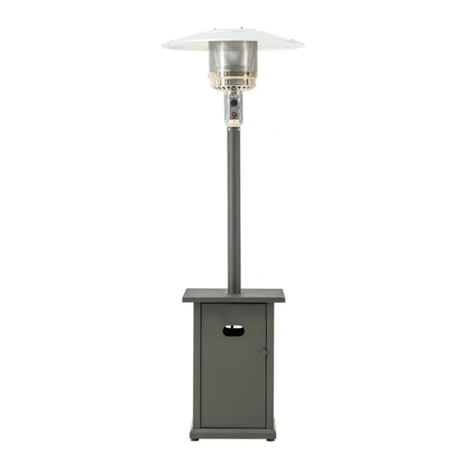
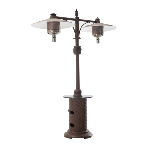
Sunjoy A306006402 User manual

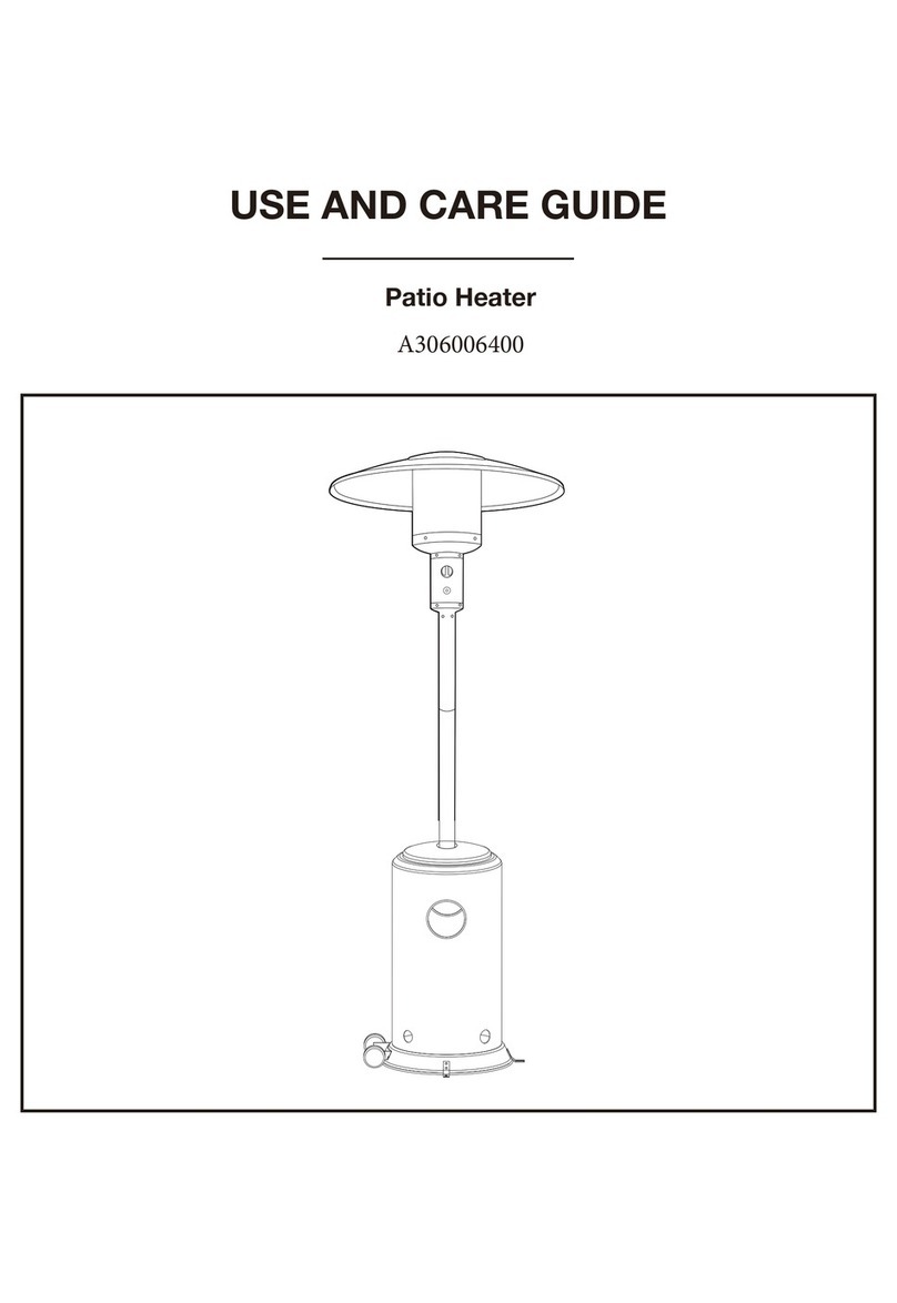
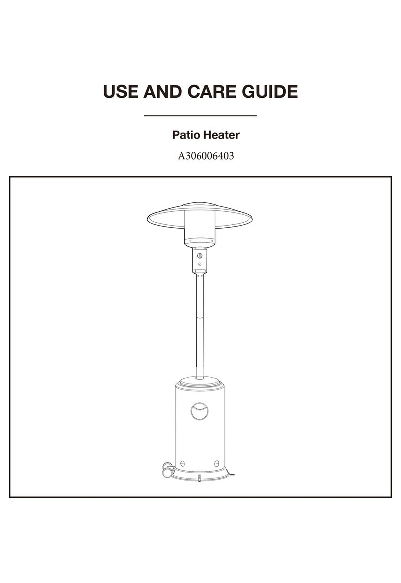
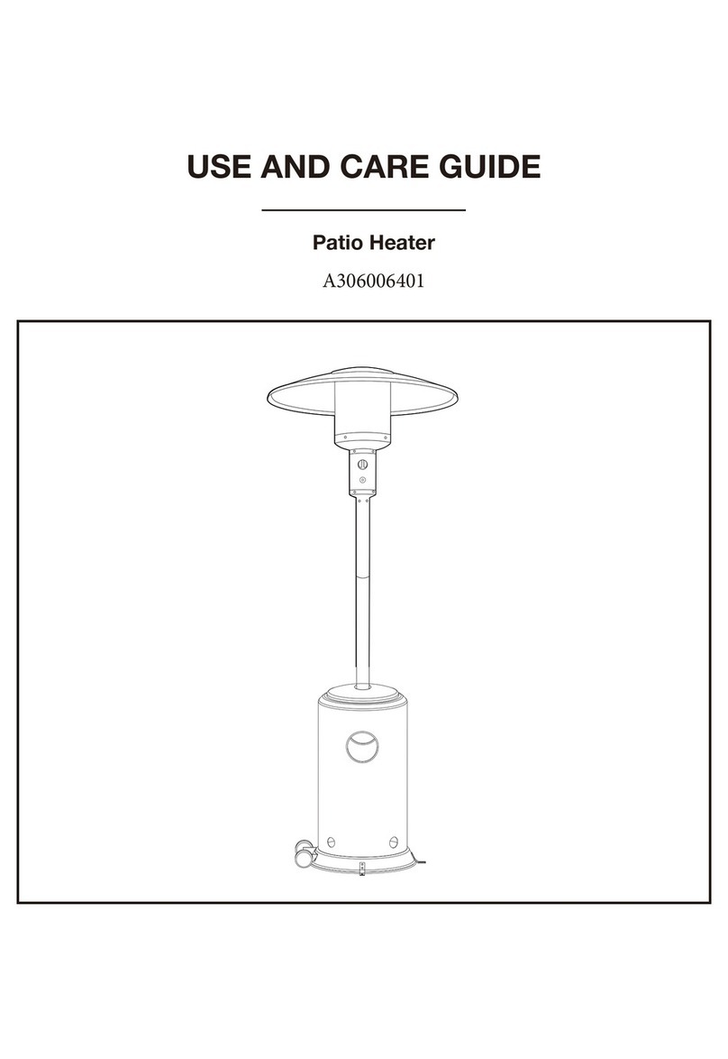
USE AND CARE GUIDE
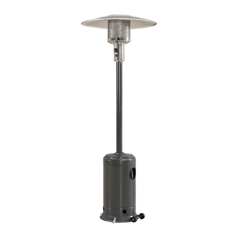
Patio Heater
A306006402

2
Table of Contents
Table of Contents ...................................2
Safety Information ................................2-3
Warranty ..........................................4
Pre-Assembly ......................................5
Planning Assembly.................................5
Hardware Included.................................5
Package Contents .................................6
Technical Data ....................................7
Assembly. . . . . . . . . . . . . . . . . . . . . . . . . . . . . . . . . . . . . . . 8-13
Operation. . . . . . . . . . . . . . . . . . . . . . . . . . . . . . . . . . . . . . 14-16
Leak Testing.....................................16
Gas And Regulator ................................16
Maintenance ......................................17
Flame Characteristic ..............................17
Screw and Bolt Connections ........................17
Storage ........................................17
Service.........................................17
Care & Cleaning ...................................17
Troubleshooting ...................................18
Safety Information
DANGER
If you smell gas:
1. Shut off gas to the appliance.
2. Extinguish any open flame.
3. If odor continues, keep away from the
appliance and immediately call your gas
supplier or fire department.
DANGER
Do not store or use gasoline or other
flammable vapors and liquids in the vicinity
of this or any other appliance.
An LP-cylinder not connected for use shall
not be stored in the vicinity of this or any
other appliance.
WARNING: For Outdoor Use Only.
WARNING: Improper installation,
adjustment, alteration, service or
maintenance can cause property damage,
injury or death. Read the installation,
operating and maintenance instructions
thoroughly before installing or servicing
this equipment.
WARNING: NEVER use indoors, in an enclosed area or
below ground level.
WARNING: This appliance is intended for use with LP
bottled gas only.
WARNING: Failure to read and follow these instructions
could result in serious injury or damage to property.
WARNING: DO NOT move this product when in use.
WARNING:
dangerous.
WARNING:
WARNING: NEVER operate the heater with the top half
WARNING: DO NOT leave this product unattended when
in use.
WARNING: Always keep the cylinder level and vertical
when positioning inside the base.
36 91

3
WARNING:
unit being tipped over, the gas supply will be cut off from
the cylinder. In this event, the knobs should be set to off and
you should wait 5 minutes before re-lighting.
WARNING: This product will become hot when in use –
take care when touching.
WARNING: Keep children and pets at a safe distance
from the unit when in use.
WARNING:
WARNING: When positioning, ensure the unit is a
from all sides and above.
WARNING: Always leak test the unit before use, annually,
or after storage, when parts are replaced/serviced or if the
gas cylinder is removed or replaced.
WARNING: When storing the appliance or gas cylinder,
WARNING: Regularly check that the regulator seal and
if necessary.
WARNING: Always follow the care and maintenance
instructions – regularly maintain your appliance.
WARNING: Always replace worn parts – do not use the
appliance if a leak, wear, or damage is found.
WARNING: DO NOT store or cover the appliance until fully
cooled.
WARNING: Always shut off the valve at the gas cylinder
or the regulator before moving the appliance.
WARNING: In the event of high winds particular attention
must be taken. Store the unit away or ensure it is at a safe
distance from other items in the event that the unit is blown
over.
WARNING:
to be used with patio heaters.
WARNING: Ensure the heater is at a safe distance from
glass and PVC doors and windows to stop damage from any
heat build up.
WARNING: Read the warnings and use instructions
before operation.
WARNING:
the patio heater in the tilt position during rain or windy
conditions or when the patio heater is not in use or
the full down position when not in use or during windy or
rainy conditions.
WARNING: FUELS USED IN LIQUEFIED PROPANE GAS
APPLIANCES, AND THE PRODUCTS OF COMBUSTION OF
SUCH FUELS, CAN EXPOSE YOU TO CHEMICALS INCLUDING
BENZENE, WHICH IS KNOWN TO THE STATE OF CALIFORNIA
TO CAUSE CANCER AND CAUSE BIRTH DEFECTS OR
OTHER REPRODUCTIVE HARM. For more information go to:
www.P65Warnings.ca.gov.
WARNING: It is normal for the heater to smoke during the
WARNING: If you smell gas – turn off the appliance and
contact your gas supplier.
WARNING:
immediately disconnect the gas cylinder moving it away
YOURSELF AT RISK!
WARNING: Ensure aerosols are not used near this unit
when in use.
WARNING: Ensure all packaging and plastic bags are
disposed of safely.
Safety Information (continued)
NOTE: THESE INSTRUCTIONS ARE FOR YOUR SAFETY.
PLEASE READ THEM THOROUGHLY BEFORE USE AND RETAIN
THEM FOR FUTURE REFERENCE.
5
Pre-Assembly
PLANNING ASSEMBLY
When you are ready to start, make sure that you have the right tools at hand, plenty of space and a clean dry area for assembly.
HARDWARE INCLUDED
NOTE: Hardware not shown to actual
size.
NOTE: It is recommended that the carton is cut open and
during assembly.
WARNING: While every precaution has been made in the
manufacture of this product, care must be taken during
assembly in case sharp edges are present.
NOTE: Refer to the assembly diagrams as necessary.
NOTE: Please lay out all nuts and bolts and check lengths
before assembly.
Item
AA
BB
CC
DD
EE
Description
M6x12 Bolt
Qty
8
14
3
6
1
3
3
6
3
3
9
9
1
M6 Nut
M8 Bolt
M6x22 Bolt
Wrench
Reflector Stud
Wing Nut
Washer
Anchoring Arm
Anchoring Nut
Cap Nut
Small Screw
Webbing
FF
GG
HH
II
JJ
KK
LL
MM

6
Pre-Assembly (continued)
PACKAGE CONTENTS
Item
A
B
C
D
E
F
Description
Reflector Panel
Center Reflector
Head Assembly
Qty
3
1
1
1
1
1
Part
G
H
I
Description
Support Legs
Quantity
3
1
1
Post
Tank Housing
Post Support
Base
Wheel Assembly
I
H

7
Pre-Assembly (continued)
TECHNICAL DATA
Overall Height
Overall Weight
Overall Width
Heater Heat Input (·Qn)
Heater Gas Consumption
Heater Injector Size
Setting Pressure
Regulator Outlet Pressure
Standard
Gas Supply Pressure
88 in. approx.
35.2 lbs
30 in.
47,000 Btu/h
1.77 Lbs per hour
0.0778 in.
11.0 in. per W.C
11.0 in. per W.C
ANSI Z83.26-2014 Gas Fired Outdoor infrared Patio heaters
Max. 150 PSI, MIN.5 PSI

8
Assembly
1Attach wheel assembly to base
2
Align the holes in the wheel assembly (I) with the holes
in the base (H), and attach the wheel assembly to the base
using two M6x12 bolts (AA) and two M6 nuts (BB).
Mount the three anchoring arms (Il) to the holes on the
base (H) using six M6x12 bolts (AA) and six M6
nuts (BB).
The patio heater need fix by hammering the three
anchoring nuts (JJ) into the ground through the anchoring
arms after assembly.
H
IH
Attach ground fixtures to base
BB
AA
AA
BB
AABB
II
JJ

9
Assembly (continued)
3Attach support legs to base
4Attach post support to the support legs
Attach the three support legs (G) to the top of the base (H)
using three M8 bolts (CC).
Attach the post support (F) to the top of the support legs
(G) using six M6 x 22 bolts (DD) and six M6 nuts
(BB).
BB
G
CC
H
G
DD
F

10
Assembly (continued)
5Place the tank housing
6Attach reflector studs to head assembly
Place the tank housing (E) on top of the assembly. Screw the threaded end of the reflector studs (FF) into
the top holes of the head assembly (C).

11
Assembly (continued)
8
7
Slide two reflector panels (A) together and assemble the
outer rim using one small screw (LL) and one cap nut (KK).
Repeat this step with the third reflector panel (A). Once
completed place the center reflector (B) in the middle and
fasten using three small screws (LL) and three cap nuts (KK).
Tighten all screws tightly.
Attach the reflector assembly made in step 7 to the top of
the reflector studs (FF) on the head assembly (C). Fasten
with six flat washers (HH) and three wing nuts (GG).
WARNING: Remove plastic protective coating on
the reflector panel (A) and center the reflector (B)
before assembling!
Install reflector Attach the reflector to the head assembly
LL

12
Assembly (continued)
10
9
Unscrew the four screws that are preassembled on the
head assembly (C). Place the head assembly (C) into the top
of the post (D) by inserting the regulator (H) into the post
(D). Tightly fasten the previously removed screws back into
the head assembly (C) through the slots at the top of the
post (D).
Remove the preassembled screws from the post support
(F) and attach the post (D) to the post support (F) using those
four screws.
Attach head assembly to post Attach post to the post support

13
Assembly (continued)
12
Turn the cylinder valve on the tank clockwise to close the
propane tank. Attach the regulator (H) to the cylinder valve
by turning the regulator coupling nut clockwise. Make sure
it is fastened securely and tighten connections by hand
only.
11
Place the gas cylinder in the base
Place the 20 lb gas cylinder in the center of the base and fasten
it with the webbing (MM).
Attach the regulator to the
cylinder valve

When lit for the first time the heater may emit a slight odor and smoke. This is a normal
and temporary condition. Emitter screen will become a bright red due to the heat. The
color is more visible at night. Flame patterns should be a blue flame; these flames should
not be yellow in color; indicating an obstruction of airflow through the burners.
1. Turn control knob clockwise to the off" position.
2. Close the cylinder valve on the propane gas tank if you don't intend to use it for a long
time.
14
Operation
To Light
TO EXTINGUISH
Before performing a leak test, be sure that no sparks can occur and you are in a spacious outdoor area. Connect the propane gas
tank to the regulator and turn the valve on the unit to the "off" position. Brush a soap and water mixture on all connections. Turn the
gas supply on; if bubbles occur on any connection there may be a leak. If you smell gas or a leak is discovered turn the gas valve off,
disconnect propane gas tank and do not use the appliance until the leak is repaired.
Do not use the heating unit without inspecting the gas hose. If there are signs of wear or abrasion you must replace the hose (if
applicable).
1. Turn on the valve on the gas supply cylinder.
2. Press and turn the variable control knob to the 'Hl' position.
3. Press down the variable control knob and hold for 30 seconds.
4. While holding down the variable control knob, press the igniter button several times until the burner head flame ignites.
Release the variable control knob 10 seconds after the ignition.
5. If a new tank has just been connected, allow at least one minute or more for the air in the gas pipeline to purge out.
6. The flame can be watched and checked from the viewing hole located on the base of the burner.
7. Turn the variable control knob to the 'LO' position for 5 minutes or more
before turning the knob to desired temperature setting.
If a small flame is needed, turn the variable control knob to the 'LO' position.
8. If the burner flame goes out accidentally or it is blown out by wind,
turn off the heater and wait at least 5 minutes or more to let the gas
dissipate before lighting again to avoid possible gas explosion.
Repeat steps 2 through 4.

15
Operation (continued)
Before performing any maintenance always disconnect propane gas tank.
Keep the heating item free and clear from combustible materials.
Visually inspect burner for obstructions and keep tank enclosure free and clear from debris. Use a soft brush to get rid of mild
stains, loose dirt and soil after the burner is completely cooled down. Wipe down with a soft cloth.
Harsh weather conditions may cause stubborn stains, discoloration and possibly rust pitting.
Permanent damage may occur if powder or solvent comes in contact with painted or plastic components on this heating unit.
Keep the heating unit stored away from direct sunlight.
If storing this unit inside, disconnect the propane gas tank from the gas valve.
Not using manufacturer approved or supplied parts/accessories may result in a defective condition and void the warranty of this
heating unit.
Always place lid (if applicable) or protective cover on heating item when not in use.

16
LEAK TESTING
Your patio heater has been checked at all factory connections for leakage. To check the connection at the gas hose/regulator/cylinder:
Ensure you are in a well ventilated area.
Conrm all control knobs are in the off position.
Open the gas control valve on the bottle.
Check for leaks by brushing a solution of 50% water and 50% dish soap over the gas system joints, including all valve connections,
hose connections and regulator connections.
NEVER USE AN OPEN FLAME to test for leaks at any time.
If bubbles form over any of the joints, there is a leak.
Turn off the gas supply and retighten all joints.
Repeat test. If bubbles form again, do not use the patio heater. Please contact the helpline stated in this manual.
Leak test annually and whenever the gas bottle is removed or replaced.
GAS AND REGULATOR
The gas hose must be connected in accordance with these instructions. When installed correctly all parts of the hose should be
contained within the patio heater pole and gas cylinder chamber. No part of the hose should be outside of the patio heater body
where it could be a trip hazard or could be accidently damaged.
This appliance is for propane use only.
See instructions supplied with the regulator for correct use and attachment.
Gas bottles should never be stored on their side.
Never store gas bottles indoors.
This appliance is supplied with a propane regulator which must only be used for propane gas.
NEVER use an adjustable regulator with this appliance.
Please consult your gas dealer for the most suitable gas bottles for your regulator.
Operation (continued)
Hose/Regulator
Regulator/Cylinder
valve

17
FLAME CHARACTERISTIC
The heater should not be operated again until the unit is serviced or repaired.
SCREW AND BOLT CONNECTIONS
All screws and bolts, etc, should be checked and tightened on a regular basis.
STORAGE
Do not leave the patio heater exposed to outside weather conditions or stored in damp moist conditions.
damaged or deformed, as this will affect performance.
If the heater is to be stored indoors, the gas bottle must be disconnected and left outside in a dry, well-ventilated area, away from
any sources of heat or ignition.
Do not let children tamper with the bottle.
SERVICE
We recommend that servicing of this appliance should be performed either after every 100 hours of use or annually, which ever is
achieved soonest.
If your heater needs maintenance or is not working properly, please contact your local authorized agent for service.
It is a necessity to contact an authorized source for replacement of parts and/or servicing.
Spare parts may be obtained by contacting Hampton Bay Customer Service at 1-855-HD-HAMPTON.
Care & Cleaning
Regularly clean your patio heater between uses and especially after extended periods of storage.
Ensure the heater control is turned fully to the off position, the gas supply is shut off at the regulator or bottle / cylinder valve, and
Never douse the heater with water when its surfaces are hot.
Yellow Tip
Maintenance

Troubleshooting
18
Problem Cause Solution
The burner will not light.
The burner flame goes
off immediately after ignition.
The ignition is delayed.
The combustion on the burner is
inadequate.
The burner flame is low.
The emitter glows uneven.
There is slight smoke and odor
during initial operation.
There is thick black smoke.
The heater produces a whistling
noise when the burner is lit.
The heater produces a clicking
noise just after the burner is lit
or turned off.
There is a gas odor even when
the control knob is in the OFF
position.
There is a gas odor during
combustion.
There is carbon build-up.
The burner injector is clogged.
There is low gas supply pressure.
There is low gas pressure.
The main burner carryover ports are clogged.
There is low gas pressure.
There is not enough air.
The supply hose is bent or twisted.
There is blockage in the burner injector.
The base is not on a level surface.
The gas pressure is low.
This is residue from the manufacturing
process.
There is blockage in the burner.
Air passageways are blocked.
There is air in the gas line.
The metal is expanding and contracting.
There is a gas leak.
The gas control is defective.
There is foreign matter in the gas or on the
burner ports.
The heater is burning vapors from paint or
impurities in the air.
There is gas leaking from the
regulator and hose connection, the valve
and pipe connections, and the pipes.
There is dirt or film on the reflector and
flame screen.
Clean the burner injector.
Call your gas supplier.
Clean the main burner ports.
Call your gas supplier.
Check the air passageways and burners for
dirt and debris, and clean with compressed air.
Straighten the hose and perform a leak test.
Clean or replace the burner injector.
Place the heater on a level surface.
Replace the cylinder with a new cylinder.
This will stop after approximately 30 minutes
of operation.
Turn off the heater and let it cool
Remove the blockage and clean the inside and
outside of the burner.
Check the minimum installation
clearances and air passageways for debris.
Operate the burner until the air is completely
purged.
This is common with heaters. If noise is
excessive, contact a qualfied service person.
Locate and correct the leak immediately.
Replace the gas control.
Check the gas passageway and burner.
Stop storing and using odor causing products
near the heater.
Locate and correct the leaks, or contact your
gas supplier.
Clean the reflector and flame screen.
Table of contents
Other Sunjoy Patio Heater manuals

Sunjoy
Sunjoy AMBERCOVE A306007500 User manual

Sunjoy
Sunjoy L-PH004PCA User manual

Sunjoy
Sunjoy A30600640 User manual

Sunjoy
Sunjoy L-PH011PSS-2 User manual

Sunjoy
Sunjoy A306006401 User manual

Sunjoy
Sunjoy L-PH004PCA User manual

Sunjoy
Sunjoy L-PH004PCA User manual

Sunjoy
Sunjoy A306006400 User manual

Sunjoy
Sunjoy AMBERCOVE A306007400 User manual

Sunjoy
Sunjoy A306004300 User manual
Popular Patio Heater manuals by other brands

Endless Summer
Endless Summer 92000 owner's manual

Hortus
Hortus Golden tube THH15 instructions

Prem-I-Air
Prem-I-Air EH0369 quick start guide

Blue Sky Outdoor Living
Blue Sky Outdoor Living PFP1513-CB owner's manual

Italkero
Italkero INFRA Spider User manual and assembly instructions

Myria
Myria MY4325 manual