Mosaic SRPH32 Series Owner's manual

Assembly Instructions
& User's Manual
Propane Patio Heater
Item #FSPTMV5004
Model #SRPH32-XXXX
Please keep this instruction manual for future reference
READ INSTRUCTION MANUAL BEFORE ATTEMPTING TO ASSEMBLE OR
OPERATE THIS PRODUCT.
Adult assembly required.
Keep screws and parts out of reach of children.
Customer Service: (866) 814-0585, 8:00am to 8:00pm,
Monday thru Friday Eastern Standard Time
8:00am to 5:00pm, Saturday Eastern Standard Time
Customer Service: (888) 922-2336 7:00 am to 12:00 am CST (daily)
Live Chat at: www.academy.com
Email: [email protected]
(Made in China)
Warning:
--------------------------------------OR-------------------------------------

WARNINGS AND CAUTIONS
Standard: ANSI Z83.26-2014 / CSA 2.37-2014
Read the instructions before use. This appliance must be installed in accordance with such
regulations as are enforced.
Gas-Fired Outdoor Infrared Patio Heater.
Page 1 of 23
DANGER
Do not store or use gasoline or other
flammable vapors and liquids in the
vicinity of this or any other appliance.
An LP cylinder not connected for use
shall not be stored in the vicinity of
this or any other appliance.
CAUTION
Consumer: Please keep this manual
for future reference.
WARNING
!
DANGER
!
WARNING
!
WARNING
!
This appliance can produce carbon monoxide,
which has no odor.
Never use this appliance in an enclosed space
such as a camper, tent or building.
CARBON MONOXIDE HAZARD
Using it in an enclosed space can kill you.
!
Installer: Leave the manual with the
user for future use. For Outdoor Use Only
1. Shut off gas to the appliance
2. Extinguish any open flame
3. If odor continues, keep away from
the appliance and immediately call
your gas supplier or fire department
If you smell gas:
Improper installation, adjustment, alteration, service or maintenance can
cause property damage, injury or death. Read the installation, operating
and maintenance instructions thoroughly before installing or servicing this
equipment.

TABLE OF CONTENTS
Warnings and Cautions....................................................................
2
Table of Contents...................................................................................
Tools and Parts...................................................................................6
Hardware................................................................................................8
Assembly Instructions.......................................................................9
Safety Check ..................................................................................14
Operation.........................................................................................16
Heater Placement ................................................................................19
Maintenance and Storage................................................................20
Trouble Shooting..................................................................................22
Warranty Information............................................................................23
REMINDER
BEFORE ASSEMBLY
Verify that all parts are included with your heater BEFORE you begin assembly by checking the Parts and
Hardware List. For your convenience, some parts may be pre-assembled or attached to heater components.
If all parts are not included, do not attempt to assemble heater. Call the toll free number on the cover
page for replacement parts.
Leave hardware installed HALF-TIGHTENED on the heater during assembly until unit is completely
assembled, then finish tightening all hardware installed.
YOUR OWNER’S MANUAL
Keep and store this Owner’s Manual for future reference – it contains important instructions and
procedures for safety and maintenance.
Page 2 of 23

WARNINGS AND CAUTIONS
The installation must conform with local codes
or, in the absence of local codes, with the
National Fuel Gas Code, ANSI Z223.1/NFPA 54,
NFPA58 Natural Gas and Propane Installation
Code, CSA B149.1, or Propane Storage and
Handling Code, B149.2
Children and adults should be alerted to the
hazards of high surface temperatures and
should stay away to avoid burns or clothing
ignition.
Young children should be carefully
supervised when they are in the area of the
heater.
Clothing or other flammable materials
should not be hung from the heater, or
placed on or near the heater.
Any guard or other protective device
removed for servicing the heater must be
replaced prior to operating the heater.
Installation and repair should be done by a
qualified service person. The heater should
be inspected before use and at least
annually by a qualified service person.
More frequent cleaning may be required as
necessary. It is imperative that control
compartment, burners and circulating air
passageways of the heater be kept clean.
Keeping the appliance area clear and free from
combustible materials, gasoline and other
flammable vapors and liquids.
Keeping the ventilation opening(s) of the
This appliance shall be used only in a well
ventilated space and shall not be used in a
An appliance may be installed with shelter
With walls on all sides, but with no overhead
NOTE:PLEASE READ THE FOLLOWING SAFETY RULES
WARNING:
DO NOT OBSTRUCT the flow of combustion
Page 3 of 23
!
The heater, when installed, must be electrically
grounded in accordance with local codes or, in
the absence of local codes, with the National
Electrical Code, ANSI/NFPA 70, or the Canadian
Electrical Code, CSA C22.1.
Prior to use, check for damaged parts such as
hoses, regulators, pilot or burner.
All leak tests should be done with a soapy
solution. NEVER USE AN OPEN FLAME TO
CHECK FOR LEAKAGE.
The propane hose with regulator assembly shall
be located out of pathways where people may
trip over it or in areas where the hose will not be
subject to accidental damage. and ventilation air.
cylinder enclosure free and clear from debris.
building, garage or any other enclosed area.
no more inclusive than:
cover.
Within a partial enclosure which includes an
overhead cover and no more than two side
walls. These side walls may be parallel, as in
a breezeway, or at right angles to each other.

WARNINGS AND CAUTIONS
The pressure regulator and hose assembly
Never fill the cylinder beyond 80 percent full;
NOTE:PLEASE READ THE FOLLOWING SAFETY RULES
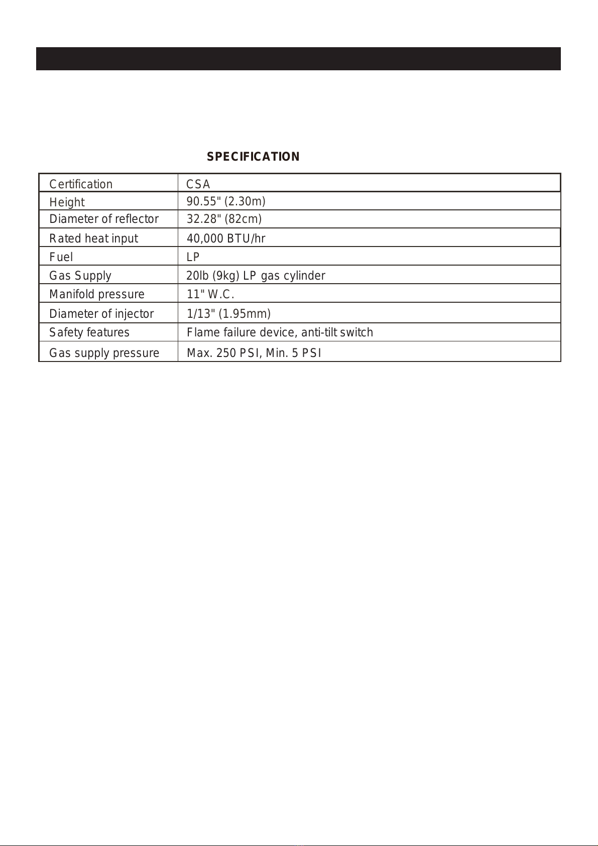
This appliance requires 9kg (20lb) LP-gas
supply cylinder.
The LP-gas supply cylinder to be used must
Constructed and marked in accordance with
the Specifications for LP-gas cylinders of
The cylinder must be disconnected when the
appliance is not in use.
from the appliance.
WARNING:
Certain materials or items, when stored under
Inspect the visible portion of the hose before
The cylinder used must include a collar to
protect the cylinder valve.
This heater is designed to operate with a standard 20lb propane cylinder with Approved Cylinder
Connection.
NOTE: PLEASE READ THE FOLLOWING
SAFETY RULES:
Perform a leak test with a soapy solution:
1. To check gas connections.
2. After connecting a new cylinder.
3. Upon re-assembly after disassembly.
Page 4 of 23
!
Within a partial enclosure which includes an
overhead cover and three side walls, as long
as 30 percent or more of the horizontal
periphery of the enclosure is permanently
open.
the U.S. Department of Transportation (DOT);
or the Standard for Cylinders, Spheres and
Tubes for Transportation of Dangerous
Goods and Commission, CAN/CSA-B339, as
applicable;
Provided with a listed overfilling prevention
device; and provided with a cylinder
connection device compatible with the
connection for the appliance.
Storage of an appliance indoors is permissible
only if the cylinder is disconnected and removed
A cylinder must be stored outdoors in a well
ventilated area out of the reach of children. A
disconnected cylinder must have dust caps
tightly installed and must not be stored in a
building, garage or any other enclosed area.
supplied with the appliance must be used,
replacement pressure regulators and hose
assemblies must be those specified by the
appliance manufacturer.
Do not store a spare LP-gas cylinder under or
near this appliance;
Do not clean the heater with cleaners that
are combustible or corrosive.
Place the dust cap on the cylinder valve
outlet whenever the cylinder is not in use.
Only install the type of dust cap on the
cylinder valve that is provided with the
cylinder valve. Other types of caps or plugs
may result in leakage of propane.
the heater, will be subjected to radiant heat
and could be seriously damaged.
each use of the appliance and inspect the
entire hose assembly at least annually.
This product can expose you to chemicals
including lead, which is known to the State of
California to cause cancer, and carbon
monoxide, which is known to the State of
California to cause birth defects or other
reproductive harm. For more information, go
to: www.P65Warnings.ca.gov.
WARNING:

WARNINGS AND CAUTIONS
Before beginning assembly of product, make sure all parts are present. If any part is missing or
damaged, do not attempt to assemble the product. Contact customer service for replacement
parts.
SPECIFICATION
Certification
CSA
Height
90.55" (2.30m)
32.28" (82cm)
LP
11" W.C.
Page 5 of 23
Diameter of reflector
Rated heat input 40,000 BTU/hr
Fuel
Gas Supply 20lb (9kg) LP gas cylinder
Manifold pressure
Diameter of injector 1/13" (1.95mm)
Safety features Flame failure device, anti-tilt switch
Gas supply pressure Max. 250 PSI, Min. 5 PSI

ST
Please check the contents of the packaging to ensure all parts are included. If missing parts
please contact customer service.
TOOLS AND PARTS
CC
BB
AA
A
B
HH
C
DD
J
D
E
EE
FF
F
G
H
GG
I
Page 6 of 23

TOOLS REQUIRED (Not included):
Adjustable open end wrench
Phillips Screwdriver
1
2
TOOLS AND PARTS
Part Description Picture
A
Quantity
1
4
1
1
1
1
1
1
1
1
B
C
D
E
F
G
H
I
Center Reflector Cap
Reflector Shields
Burner Head
Upper Pole
Lower Pole
Decorative Cap
Base
Cylinder Locking Bar
Wheel
J
Gas Hose and Regulator
Page 7 of 23
(pre-installed)

Part Description
AA
M6 Nut
BB 6mm Washer
CC
M6 x 10 Screw
M6 x 20 Bolt
DD
EE
M6 x 14 Bolt
M5 x 12 Flat Bolt
FF
GG 2
Please check the contents of the packaging to ensure all parts are included.
HARDWARE
Picture Quantity
12
18
15
6
4
4
HH M6 x 70 Double Pointed Bolt 3
Page 8 of 23
M6 x 20 Bolt Assembly

Step 1
Step 2
Step 1
Hardware Used
Hardware Used
GG x 2
Attach the wheel (I) to the base (G) with (2)
M6 x 20 bolts assembly (GG).
Step 2
WARNING: THIS APPLIANCE REQUIRES INSTALLATION BY A COMPETENT PERSON.
PROPER ASSEMBLY IS THE RESPONSIBILITY OF THE INSTALLER.
ASSEMBLY INSTRUCTIONS
Attach the lower pole (E) to the base (G) with (4)
M6 x 20 bolts (FF), then slide the decorative cap (F)
over the lower pole (E) to cover the bolts.
G
E
F
I
GG
FF
M6 x 20 Bolt Assembly
FF x 4
M6 x 20 Bolt
Page 9 of 23
!
G

Place the upper pole (D) on the lower pole (E)
Insert gas hose and regulator (J) of the burner head (C)
into the lower pole (E).
tighten with (6) M5 x 12 flat bolts (EE).
Step 4
Step 3
Hardware Used
Hardware Used
DD
Step 4
Step 3
WARNING: THIS APPLIANCE REQUIRES INSTALLATION BY A COMPETENT PERSON.
PROPER ASSEMBLY IS THE RESPONSIBILITY OF THE INSTALLER.
ASSEMBLY INSTRUCTIONS
C
E
J
D
D
C
DD
EE
M6 x 14 Bolt x 4
EE
M5 x 12 Flat Bolt x 6
Insert gas hose and regulator (J) of the burner head (C)
into the upper pole (D), then tighten the burner head (C)
to the upper pole (D) with (4) M6 x 14 bolts (DD).
Note: Make sure the regulator goes through the pole.
J
Page 10 of 23
!

Step 5
Step 6
Step 5
Hardware Used
Hardware Used
M6 x 70 Double
Pointed Bolt
6mm Washer
CC
BB
AA
Step 6
BB
HH
Fan open the reflector shields (B) and align holes
to attach the center reflector cap (A) on the top of
the four reflector shields (B) with (12) M6 x 10
screws (AA), (12) 6mm washers (BB) and (12)
M6 nuts (CC).
WARNING: THIS APPLIANCE REQUIRES INSTALLATION BY A COMPETENT PERSON.
PROPER ASSEMBLY IS THE RESPONSIBILITY OF THE INSTALLER.
ASSEMBLY INSTRUCTIONS
M6 Nut x 12
x 12
x 12
6mm Washer
M6 x 10 Screw
A
A
B
B
BB
CC
BB
AA
Thread (3) 6mm washers (BB) and (3) M6 x 70
double pointed bolts (HH) into the burner head (C).
x 3
x 3
BB
HH
C
Page 11 of 23
!

Fill at least 23 LBS of sand (not included) into
the hole.
WARNING: THIS APPLIANCE REQUIRES INSTALLATION BY A COMPETENT PERSON.
PROPER ASSEMBLY IS THE RESPONSIBILITY OF THE INSTALLER.
ASSEMBLY INSTRUCTIONS
Step 8
Step 7 Step 7
Step 8
Fill sand into
the hole till full.
BB
CC
Hardware Used
M6 Nut
6mm Washer
BB
CC
Place the reflector assembly onto the top of the
burner head (C) and tighten with (3) 6mm washers
(BB) and (3) M6 nuts (CC).
x 3
x 3
C
Page 12 of 23
!

WARNING: THIS APPLIANCE REQUIRES INSTALLATION BY A COMPETENT PERSON.
PROPER ASSEMBLY IS THE RESPONSIBILITY OF THE INSTALLER.
ASSEMBLY INSTRUCTIONS
Step 10
Attach the regulator to the cylinder and turn
clockwise to securely tighten the valve. Close
and latch the door.
Note: Make sure to check for leaks after
attaching the cylinder. (For instructions, refer
to the page14-SAFETY CHECK)
To remove the regulator, turn off the cylinder
valve and turn counterclockwise the regulator
to loosen from the cylinder.
Step 10
Tighten
gas hose and regulator
Place the gas cylinder (not included) into the
base (G) and secure with the cylinder locking
bar (H).
Step 9
H
H
G
H
Step 9
Page 13 of 23
!

SAFETY CHECK
hose
connection
brush
Check for leaks
All connections of the patio heater have been
checked for leakage. Follow these steps to check
the gas hose/regulator/cylinder connections:
1) Make leakage solution by mixing 1 part liquid
dish soap and 3 parts water.
2) Spoon or brush several drops (or use squirt
bottle) of solution onto the hose connection,
regulator & cylinder connection.
Turn on gas cylinder valve. Inspect the)3
connections and look for bubbles.
4) If no bubbles appear, the connection is safe.
5) If bubbles appear, there is a leak. Loosen
and re-tighten this connection. If the connection
still leaks, please call customer service:
1-866-814-0585 or 1-888-922-2336.
Note:
1) The cylinder supply system must be arranged
for vapor withdrawal.
2) The cylinder used must include a collar to
protect the cylinder valve.
regulator & cylinder
connection
WARNING: ONLY AN AUTHORIZED GAS TECHNICIAN SHOULD INSTALL THIS
Page 14 of 23
!
PRODUCT.

SAFETY CHECK
WARNING: ONLY AN AUTHORIZED GAS TECHNICIAN SHOULD INSTALL THIS
Page 15 of 23
!
PRODUCT. PROPER ASSEMBLY IS THE RESPONSIBILITY OF THE INSTALLER.
Annual check operation:
a. Remove the observation window panel by
un-screwing two bolts.
b. Turn on LP gas cylinder valve.
c. Spoon several drops (or use squirt bottle)
of the solution onto gas hose connection
and automatic valve connection and the
injector connection.
d. Inspect the connections and look for
bubbles.
e. If no bubbles appear, the connection is
safe.
f. If bubbles appear, there is a leak. Shut off
the LP gas cylinder valve, loosen and then
re-tighten this connection.
g. Check again for leaks.
h. If bubbles still appear, close the LP gas
cylinder vavle and call our customer
service line 1-866-814-0585 or 1-888-
922-2336.
i. Hose checking steps:
(1) Unscrew M6 x 14 bolts from the pole.
(2) Pull out the head assembly hose and
regulator from the pole.
(3) Check if there are cracks or worn
sections on the hose. If yes, replace the
hose and regulator immediately.
(4) Check for leaks according to the above
steps after replacing the hose and
regulator.

OPERATION
Page 16 of 23
!
!
WARNING: DO NOT ATTEMPT TO OPERATE HEATER UNTIL YOU HAVE READ AND
PERSONAL INJURY, DEATH, OR PROPERTY DAMAGE.
Before turning gas supply ON
Your heater was designed and approved for OUTDOOR
USE ONLY. DO NOT use it inside a building or any other
enclosed area.
Make sure surrounding areas are free of combustible
materials, gasoline, and other flammable vapors or liquids.
Ensure that there is no obstruction to air ventilation.
Be sure all gas connections are tight and there are no leaks.
Be sure the access panel is clear of debris.
Be sure any component removed during assembly or
servicing is replaced and fastened prior to starting.
Before Lighting
Heater should be thoroughly inspected before each use,
and by a qualified service person at least annually.
If relighting a hot heater, always wait at least 5 minutes.
Lighting instructions
1) Turn the control knob to “OFF” position.
2) Turn LP cylinder gas valve to fully open position.
3) Push in the gas control knob and turn counter-clockwise
to “LOW” position, this will light the burner. If needed,
keep depressing and turning control knob
counter-clockwise until the burner lights. (You will hear 1
clicking noise).
4) Once the burner is lit, continue to keep the control knob
depressed for at least 30 seconds, then release control
knob.
FOR YOUR SAFETY:
If at any time you are unable to light
burner and smell gas, wait 5 minutes
to allow gas to dissipate before
attempting to light heater.
If after 1 minute, you are unable to
light burner, wait 5 minutes and allow
flammable vapors to dissipate before
attempting to light heater.
WARNING
FOR YOUR SAFETY:
!WARNING
Allow emitter and dome to cool
before touching.
DO NOT touch or move heater
for at least 45 minutes after use.
!WARNING
Lighting operations should comply
with Lighting Instruction section.
Improper lighting operations will
cause serious injury and explosion.
UNDERSTAND ALL PRECAUTION. FAILURE TO DO SO CAN RESULT IN SERIOUS

OPERATION
Page 17 of 23
5) If burner does not stay lit, repeat steps 3 and 4 after
5 minutes.
6) If burner still does not stay lit, then:
a) Push in gas control knob and turn counter clockwise
to the “LOW” position.
b) Keep depressing the control knob, put long stem
lighter into the ignition hole on the emitter screen to
light the burner.
c) Repeat step 4.
7) Turn the control knob counter clockwise to “HIGH”
position. If you want a lower temperature, turn the
control knob clockwise to the “LOW” position.
Flame Characteristic
The flame pattern at the emitter screen should be visually
checked whenever heater is operated. Normally the burner
flame is blue, but a small yellow flame is acceptable.
If flames extend beyond surface of the emitter grid, or the
phenomena of flame lift or light back, or black spot is
accumulating on the emitter grid or reflector, the heater
should be TURNED OFF immediately. The heater should
not be operated again until the unit is serviced and or
repaired.

OPERATION
Page 18 of 23
!
!
CAUTION: AVOID INHALING FUMES EMITTED FROM THE HEATER’S FIRST USE.
SMOKE AND ODOR FROM THE BURNING OF OILS USED IN MANUFACTURING WILL
APPEAR. BOTH SMOKE AND ODOR WILL DISSIPATE AFTER APPROXIMATELY 30
MINUTES. THE HEATER SHOULD NOT PRODUCE THICK BLACK SMOKE.
NOTE:
The burner may be noisy when initially turned on. To eliminate
excessive noise from the burner, turn the Control Knbo to the
“LOW” position. Then, turn the knob to the level of heat desired.
When heater is ON:
Emitter screen will become bright red due to intense heat. The
color is more visible at night. Burner will display tongues of blue
flame. These flames should not be yellow or produce thick black
smoke, indicating an obstruction of airflow through the burners.
Operation pressure checked:
If the flame is very small, this is because the supply pressure is
not enough. Please refill gas cylinder.
Re-light:
1) Turn the control knob to “OFF” position.
2) Wait five (5) minutes before attempting to relight burner.
3) Repeat steps beginning with step 2 of the lighting instruction
above.
Shut down instructions:
1) Push in and turn control knob clockwise to “OFF” position.
2) Turn LP cylinder gas valve clockwise to “OFF” position when
heater is not in use.
NOTE: After use, some discoloration of the emitter screen is
normal.
The Event of Gas Leakage:
1) Turn the control knob to “OFF” position.
2) Turn LP cylinder valve to “OFF” position.
3) Wait 5 minutes to allow gas to dissipate.
4) If odor continues, immediately call gas supplier or fire
department.
WARNING: Heater will be hot after use.
Handle with extreme care.

HEATER PLACEMENT
CAUTION: WHEN CERTAIN MATERIALS OR ITEMS ARE LEFT, ABOVE, BESIDE OR
UNDER THIS HEATER WHILE IN USE, THEY WILL BE SUBJECT TO RADIANT HEAT AND
COULD BE SERIOUSLY DAMAGED.
This heater is primarily used for the heating of
outdoor patios, decks, spas, pools and open
working areas.
Always make sure that adequate fresh air
ventilation is provided. Follow the spacing
tolerances shown in the following figure 1 at
all times.
This heater must be placed on level, firm
ground.
Never operate in an explosive atmosphere.
Keep away from areas where gasoline or other
flammable liquids or vapors are stored or used. Figure 1
Page 19 of 23
!
This manual suits for next models
1
Table of contents
Other Mosaic Patio Heater manuals
Popular Patio Heater manuals by other brands

BOND MANUFACTURING
BOND MANUFACTURING HYPH4601-1 owner's manual

Blumfeldt
Blumfeldt Fiamme Tamburo manual

Nuu Garden
Nuu Garden AH003 instruction manual

JR Home
JR Home Paramount SHCTPH-SS-BK owner's manual

ellos
ellos 1675332-01-0 Safety instructions and operation manual

Hiland
Hiland NG-GT-BRZ owner's manual