Sunjoy L-PH004PCA User manual

February16 MadeinChina 1/ 12
Owner’s Manual
Dual Head Standing Patio Heater
L-PH004PCA
WARNING: FOR YOUR SAFETY
State of California Proposition 65
Warning: Propane and byproducts of
combustion of propane contain chemicals
known to the State of California to cause
cancer, birth defects, or other reproductive
harm.
Propane cylinder required (not included)
1 AA 1.5V battery required (not included)
DANGER CARBON MONOXIDE HAZARD
This appliance can produce carbon monoxide which has no odor.
Using it in an enclosed space can kill you.
Never use this appliance in an enclosed space such as a camper,
tent, car or home.
WARNING: If the information in this manual is not
followed exactly, a fire or explosion may result causing
property damage, personal injury or loss of life.
DANGER
If you smell gas:
Shut off gas to the appliance.
Extinguish any open flame.
If odor continues, keep away from the
Appliance and immediately call your gas
supplier or fire department.
WARNING: Improper installation,
adjustment, alteration, service or maintenance
can cause injury or property damage. Read the
installation, operating and maintenance
instructions thoroughly before installing or
servicing this equipment.
WARNING
Do not store or use gasoline or other flammable
vapors and liquids in the vicinity of this or any
other appliance.
An LP-cylinder not connected for use should
not be stored in the vicinity of this or any other
appliance.
WARNING: For Outdoor Use Only.
This appliance complies with “ANSI Z83.26-2014/CSA 2.37-2014, Gas Fired Outdoor Infrared Patio Heater.

February16 MadeinChina 2/ 12
Table of Contents
Specification ……………………………………………………………………………………..
Introduction …………………………………………………………………………………...
1. Safety information ……………………………………………………………………..
2. Product diagram and package list…………………………………………………..
3. Assembly instruction and tools required………………………………………….
4. Operation ………………………………………………………………………………..
4.1 Leak check………………………………………………………………………….
4.2 Ignition and setting control………………………………………………………
4.3 Shut down…………………………………………………………………….........
5. Storage …………………………………………………………………………………..
6. Maintenance …………………………………………………………………………….
7. Replacement parts list…………………………………………………………………
8. Troubleshooting.……………………………………………………………………….
9. Service …………………………………………………………………………………..
10. Warranty terms………………………………………………………………………….
2
3
3
4-5
6-7
8-10
8
9-10
10
10
10
11
11
12
12
IMPORTANT
Read this manual carefully before assembling, using or servicing this patio heater. Keep this manual
for future reference. For technical assistance on assembly or replacement parts, you can call us
toll-free at 1-866-578-6569 from 8 a.m. EST to 8 p.m. PST or email to customer.care@sunjoygroup.com
or visit www.sunjoyonline.com to place your order or fax your parts replacement order form together
with your purchase receipt to 1-740-283-3549 for assistance.
Installation and service must be performed by a
qualified installer, service agency or gas supplier.
Installer: Leave this manual with consumer
Consumer: Keep this manual for future reference.
SPECIFICATIONS
Rated Heat Input 33,000 BTU/Hr per burner, 64,000 BTU/Hr dual burners
Fuel Liquid Propane Gas
Gas Supply 20 lb. LP-Gas cylinder
Manifold Pressure 11 inches W.C
Orifice Size (diameter) 2.00 mm
Safety Features Flame failure device, Tilt switch
Gas Supply Pressure Max. 250 PSI, Min. 5 PSI

February16 MadeinChina 3/ 12
INTRODUCTION
Thank you for choosing Dual Head Standing Patio Heater as your form of outdoor heating.
Please take time to read these instructions thoroughly and follow each step carefully for safe and easy
operation.
1. SAFETY INFORMATION
To ensure safe use of your patio heater, pay close attention to these essential safety requirements.
This appliance must only be used outdoors in a well ventilated area,
and shall not to be used in a garage or any other enclosed space.
The tank must have a valve with external right hand thread to match
the appliance connection device.
With walls on all sides ,but with no overhead cover.
Within a partial enclosure which includes an overhead cover and no
more than two side walls . These side walls may be parallel ,as in
a breezeway ,or at right angles to each other.
Within a partial enclosure which includes an overhead cover and three side walls, as long as 30
percent or more of the horizontal periphery of the enclosure is permanently open.
Constructed and marked in accordance with the Specifications for LP-gas cylinders of the U.S.
Department of Transportation(DOT);or the Standard for Cylinder, Spheres and Tubes for
Transportation of Dangerous Goods and Commission ,CSA B339,as applicable;
Provided with a listed overfilling prevention device;
Provided with a cylinder connection device compatible with the connection for the appliance.
Do not store a spare LP-gas cylinder under or near this appliance;
Never fill the cylinder beyond 80 percent full;
For appliances designed to use a CGA No.791 Connection:”Place the dust cap on the cylinder
valve outlet whenever the cylinder is not in use. Only install the type of dust cap on the cylinder
valve that is provided with the cylinder valve. Other types of capes or plugs may result in leakage
of propane.
Use only 20lb LP-Gas tank with size of 18.1in / 46cm (Height)*12.5in / 32cm (Width).
Certain items or material, when stored under the heater or nearby will be subjected to radiant
heat and could be seriously damaged.
Always place heater on a firm and level surface.
Always keep at least 50in / 127cm side clearance and 50in / 127cm to top from any combustible
materials.
Always keeps at least 39.3in/100cm clearance around air opening into the combustion chamber.
Do not use if the wind velocity is greater than 10 miles/hr / 16 km/hr.
Do not use if the environment temperature is below 40oF / 4.4oC.
Do not spray aerosols near the heater while in use.
Do not move the heater while in use.
Any guard or other protective device removed while servicing the heater must be replaced prior
to operating the heater.
Clothing or other flammable materials should not be hung from the heater, or placed on or near
the heater.
Children and adults should be alerted to the hazards of high surface temperatures and
stay away to avoid burns or clothing ignition.
Young children and pets should be carefully supervised when they are in area of heater.
Do not alter or modify the heater in any manner.
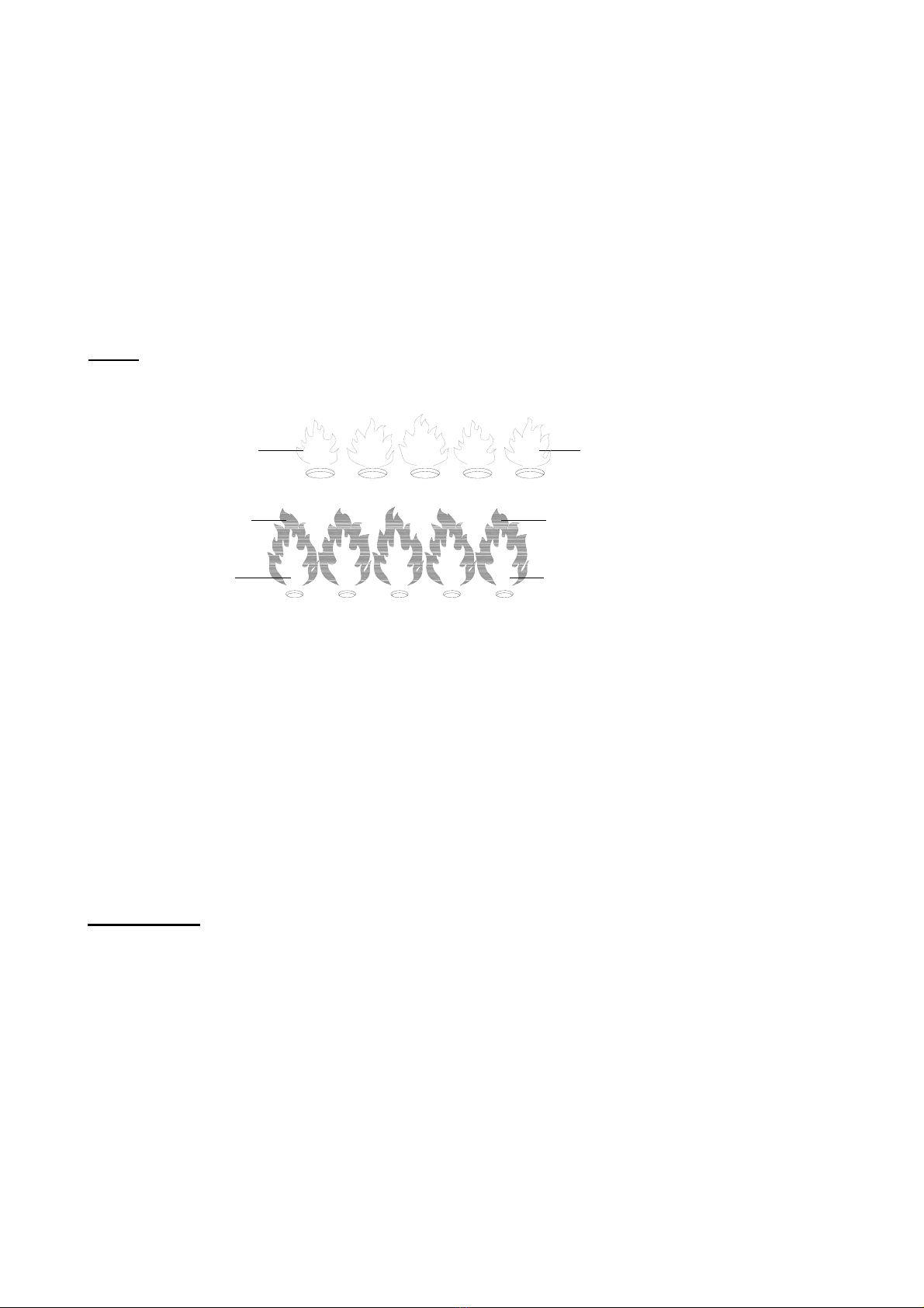
Conduct leak test only with soapy water whenever a cylinder is connected, looking for bubbles.
Turn the control knob to “OFF” position when heater is not in use.
Allow 45 minutes to cool down after use before attempting to move your heater.
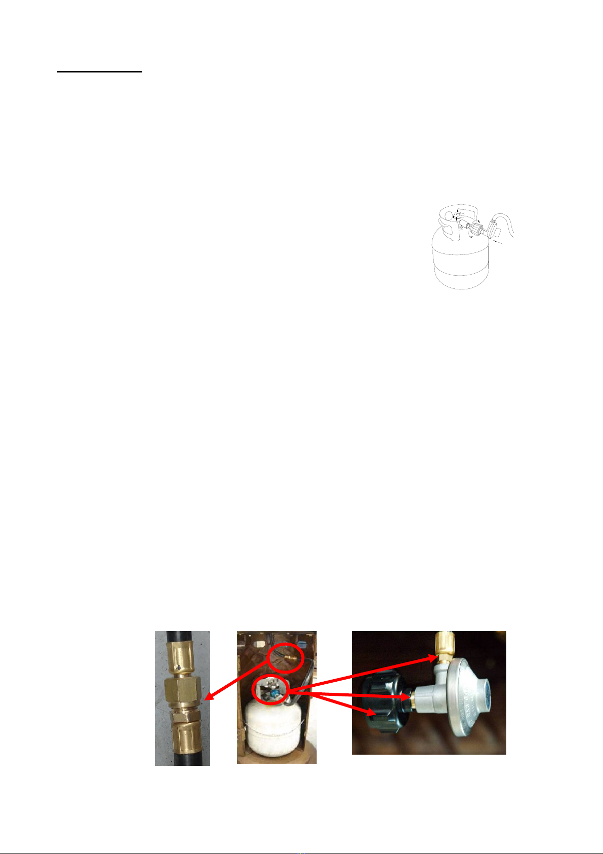
Gas supply must be turned off at the supply tank while not in use, disconnect the gas supply tank
by unscrewing counter-clockwise the connecter of the regulator.
Fig.1

February16 MadeinChina 4/ 12
Installation and repair should be done by a qualified service person. The heater should be
inspected before use and at least annually by a qualified service person.
More frequent cleaning may be required as necessary. It is imperative that the control
compartment, burners and circulating air passageways of the heater be kept clean.
Tank supply system must be arranged for vapor withdrawal. The tank used must include a collar
to protect the cylinder valve.
The pressure regulator and hose assembly provided with the appliance must be used. Replace
only with the pressure regulator and hose assembly supplied by manufacturer.
The heater, when installed, must be electrically grounded in accordance with local code or, in the
absence of local codes, with the National Electrical Code, ANSI/NFPA 70.
The minimum permissible gas supply pressure for purpose of input adjustment is 122 PSI.
2. PRODUCT DIAGRAM AND PACKAGE LIST
2.1 Product Diagram
Fig. 2
L.Base
N.Door
G.Table top base
E.Table top
D.Table top decorative
H.Shroud Panel (left)
J.Shank(rear)
K.Shank(left)
Q.Regulator
P.Shank(right)
M.Shroud Panel (right)
C.Dome brim
F.Post
A.Post decorative
B.Engine

February16 MadeinChina 5/ 12
2.2 package list (one carton)
Item Description QTY Item Description QTY
A Post Decorative 1 J Shank (rear) 2
B Engine 1 K Shank (left) 1
C Dome Brim 2 L Base 1
D Table Top Decorative 1 M Shroud Panel (right) 1
E Table Top 1 N Door 1
F Post 1 P Shank (right) 1
G Table Top Base 1 Q Regulator 1
H Shroud Panel (left) 1 Hardware Pack 1
Hardware Pack including:
ITEM PICTURE Description QTY ITEM PICTURE Description QTY
LA Bolt 18 LH Washer 6
LB Nut 14 LI Cap Nut 16
LC Screw 6 LJ Screw 1
LD Screw 6 LK Wrench 1
LE Screw 11 LL Nut 2
LF Screw 16 LM Lock Washer 4
LG Washer 18

February16 MadeinChina 6/ 12
3. ASSEMBLY INSTRUCTION
3.1 Tools required
One Wrench (attached in Hardware Pack), one Philip Screw Driver and two Adjusting Wrenches.
3.2 Assembly Instructions
(Please refer to the attached Diagrams)
Step1. Install 4 Shanks
Carefully install Shank (left) (chain & hinges
attached), Shank (rear) and Shank (right) on base at
correct position by using 4 bolts (LA), 4 washers (LG)
and 4 lock washers (LM).
Do not fasten screws tightly.
Step2. Install Table Top Base
Install Table Top Base on Shanks by using 8 bolts
(LA), 8 nuts (LB) and 8 washers (LG).
Do not fasten screws tightly.
Step3. Install Shroud Panel (left), Shroud Panel
(right).
Install Shroud Panel (left) on Shank (left) and Shroud
Panel (right) (with lock catch) on Shank (right) by
using 6 screws (LE), Connect Shroud Panel (left) and
Shroud Panel (right) by using 2 screws (LE) and 2
nuts (LL). Fasten screws tightly.
Step4. Install Door
Attach Door to hinge of Shank (left) by using 6
screws (LD), close Door, and adjust Shroud Panels
and door until no gap exists, and then fasten all
previous screws.
Fig.3 Fig.4
Fig.5 Fig.6
*.***

February16 MadeinChina 7/ 12
Step5. Install Post
Install Post on Table Top Base by using 6 bolts (LA),
6 nuts (LB) and 6 washers (LG).
Step6. Install Table Top & Table Top Décor
Carefully install Table Top on Table Top Base by
using 6 screws (LC) and 6 washers (LH).
Put down Table Top Decorative through Post on
Table Top.
Step7. Attach Dome Brim to burning system
Attach Dome Brim to burning system by using 16
screws (LF) and 16 cap nuts (LI), cap nuts on the
upper dome cover.
Step8, Attach Post Décor
Attach Post Decorative piece to Engine by fastening
screw (LJ).
Step9. Install gas assembly
Insert gas line through Post and slide fixing end of
Engine into Post, align/place control knobs of
Engine and labels of Post at the same side and
fasten with 3 screws (LE).
Warning: The upper frame is heavy; assistance
may be needed for this step.
Step10. Connect Regulator and Gas Line
Hand screw coupling of regulator hose into coupling
of connector hose. Tighten fully using 2 adjusting
wrenches.
Fig.10
Fig.12
Fig.11
Fi
g
.8Fig.7
Fig.9

February16 MadeinChina 8/ 12
4. OPERATION
This dual head patio heater has two heat units which are convenient for warming oneself.
The burners can be turned on individually or together.
Left burner will operate by turning on left control knob, right burner will operate by turning right control
knob.
IMPORTANT: Use only standard 20 lb propane cylinder constructed and marked in accordance
with the specifications for LP-gas cylinder of the U.S. Department of Transportation (D.O.T.).
4.1 Leak check
Caution: Do not use a naked flame to test for leaks.
4.1.1 Preparation
(1) Make leak check solution by mixing soap and water 1 part to 1 part.
(2) Make sure BOTH Control Knobs are at OFF position.
(3) Place the gas cylinder inside the cylinder cabinet and hook up it with chain.
(4) Then screw clockwise the connecter of the regulator into the valve of gas cylinder. (See Fig.13)
(5) Visually inspect the visible portions of hose prior to each use by opening the door of cylinder
cabinet. If there are breaks, wear, and/or abrasion, please replace it with component supplied by
manufacturer.
(6) On an annual basis visually check at least annually portions of the hose assembly located within
the confines of the heater post by pulling out the hose from post after detaching regulator and
unscrewing the screws between post and control housing.
(7) Hook chain up after placing gas cylinder inside of the cylinder cabinet in order to stabilize the gas
cylinder.
NOTE: Be careful not to kink flexible gas hose. If gas hose is kinked, gas flow could be reduced, or a
gas leak could occur.
4.1.2 Connections between cylinder and gas line. (See Fig.14)
(1) Turn the valve of gas cylinder on.
(2) Brush or spoon several drops of soapy solution around the connections between cylinder and gas
line. Visually inspect whether or not bubbles appear at these connections.
(3) If no bubbles appear, the connection is secure, continue to the next step.
(4) If bubbles appear, there is a leak. Turn off the valve of gas cylinder, reconnect these connections,
and then conduct leak check again.
Fig.13
Fig.14

February16 MadeinChina 9/ 12
4.1.3 Connections between gas line and gas valve.
(1) Be sure the valve of gas cylinder is on.
(2) Brush or spoon several drops of soapy solution around the connections
through the leak check holes on pole. Inspect whether or not bubbles appear
at these connections. (See Fig.15)
(3) Unscrew and remove cover of control housing, brush or spoon several
drops of soapy solution around the connections. Inspect whether or not
bubbles appear at these connections. (See Fig.16)
(4) If no bubbles appear, the connection is secure.
(5) If bubbles appear, there is a leak. Turn off the valve of gas cylinder, reconnect gas line and engine,
and then conduct leak check again.
4.1.4 Connections between gas line and left (right) burner assembly.
(1) Be sure the valve of gas cylinder is on. Push and turn on left control knob for checking the leakage
of left burner assembly, and right control knob for right burner assembly.
(2) Unscrew and remove dome décor, brush or spoon several drops of soapy solution around the
connections. Inspect whether or not bulbs appear at these connections. (See Fig.17)
(3) If no bubbles appear, the connection is secure.
(4) If bubbles appear, there is a leak. Turn off control knob, reconnect gas line and engine, and then
conduct leak check again.
Note: If the leak still persists, please call 1-866-578-0101 for assistance.
4.2 Ignition and setting control
4.2.1 Unscrew the igniter cap and put 1 AA 1.5V battery
into compartment with anode outward, and then
reset the igniter cap.
Note: If the battery of the igniter has run out of
electricity, replace with a new battery.
Please remove battery when not in use for an
extended period of time.
4.2.2 Make sure control knobs are at OFF.
Fig.15
Fig.16
Fig.17
Igniter button
Control knob
Fig.18

February16 MadeinChina 10 / 12
4.2.3 Turn on gas cylinder valve.
4.2.4 Depress and hold igniter button, press in and turn left (right) control
knob counterclockwise to High to light the burner. If left (right) burner is lit,
release igniter button, and continue to hold in control knob for 1 to 2
minutes to heat thermocouple. When control knob is released, burner
should be lit. If not, press in and turn control valve knob clockwise
to OFF. Wait a full 5 minutes, and then repeat above steps.
4.2.5 Turn control knob to HIGH ~ LOW for desired heat input. (See Fig.18)
Warning: Lighting the patio heater improperly could lead to an unsafe condition.
NOTE: While in use, the burner flame should be mainly blue in appearance with a small amount of
yellow. The flame can be identified by the following Figure.
BLUE LOW
YELLOW TIPS
BLUE
HIGH
LOW
1- Flame should be blue with slight yellow tips.
2- Light burner, rotate knob from HIGH to LOW. You should see a smaller flame in LOW position than
seen in HIGH position. Always check flame prior to each use. Perform flame check prior to each
use. If only low flame is seen refer to “Burner flame is low” in the Troubleshooting Section.
4.3 Shut down
4.3.1Turn control knobs clockwise to OFF to shut down the patio heater.
4.3.2 Open the door of Cylinder Cabinet and turn off gas supply at gas supply cylinder.
4.3.3 Disconnect by unscrewing counter-clockwise the connecter of the regulator and remove the gas
cylinder when the patio heater is not in use.
5. STORAGE
Allow at least 45 minutes for the heater to cool down after using.
Disconnect and remove cylinder if stored indoors.
Store the propane tank in a cool, dry and well ventilated area, out of the reach of children, and not
in a building, garage or any other enclosed area.
Store the heater upright in a sheltered area away from inclement weather and dust.
If desired, cover the heater after the heater is cool.
Storage indoors is permissible only if the propane tank is disconnected and removed from the
appliance.
Fig.19 Incorrect flame
Fig.20 Correct flame

February16 MadeinChina 11 / 12
6. Maintenance
To obtain the best performance from your heater, make sure you perform the following maintenance
activities on a regular basis:
Keep exterior surfaces clean. Use warm soapy water for cleaning. Never use flammable or
corrosive cleaning agents. Be sure to keep the area around the burner and control assembly
dry at all times. Airflow must be unobstructed. Clear insect nests or webs away from your heater’s
exterior and interior.
Carbon deposits may create a fire hazard. Clean dome and emitter with warm soapy water if
required.
Check your heater for signs of damage or wear and replace components as necessary.
Check the hose located within the confines of the enclosure.
Keep the appliance area clear and free from combustible materials, gasoline and other flammable
vapors and liquids.
Keep the ventilation openings of the cylinder enclosure free and clear from debris.
Visually check the burner flame with pictorial representations.
7. REPLACEMENT PARTS LIST
Item Description Item Description
U Control Knob X Electrode
V Igniter Y Thermocouple
W Tilt Switch Z Regulator
If you want to replace the parts listed, please consult 1-866-578-6569 for assistance and advice.
8. Troubleshooting
PROBLEM WHAT TO DO?
Burner won’t light Does the Gas Cylinder contain gas?
Check the Gas supply is connected and/or turned ON?
Is the correct Gas type connected?
Check if the Spark Igniter is working. To do this, look through the viewing
hole. If you can’t see the spark you may use a lighted match.
Check the Gas Pressure.
The Thermocouple may need replacing
The Burner jet may be blocked.
Burner flame is low The Gas Cylinder may be low on gas.
Is the Control Knob positioned at “HIGH”?
The Burner Jet may be partially blocked.
Check the Gas Pressure.
Burner emits smoke The Burner will burn off oily materials when it’s first lit.
Persistent smoke could suggest a partial blockage within the Burner itself.
Carbon deposit on
Emitter and dome
Build-up of carbon can accumulate over time. Wipe off before lighting.

February16 MadeinChina 12 / 12
9. SERVICE
For technical assistance on assembly or replacement parts, you can call us toll-free at
www.sunjoyonline.com to place your order or fax your parts replacement order form together with
your purchase receipt to 1-740-283-3549 for assistance.
Warning:
Use original equipment replacement parts only. Use of unauthorized parts or
modification of parts will void the warranty and create an unsafe condition.
10. WARRANTY TERMS
Subject to the conditions set out below, this product is warranted to the original purchaser to be free
from defects in workmanship and materials for 12 months from the date of purchase.
10.1 Satisfactory proof of the purchase date must be furnished at the time of notification of the defect
for any claim under the warranty to be enforceable.
10.2 This warranty covers all parts found defective in workmanship and/or materials during the
warranty period and can be repaired or replaced at the discretion of the manufacturer at no cost
to the original purchaser.
10.3 This warranty will be void and accordingly no claim of any nature will be enforceable if the product
has not been assembled, installed or operated according to the instructions, subjected to abuse,
improperly treated, neglected, rusted by exposure to the elements, misused and/or if any repairs,
maintenance, or service has been done by an unauthorized person.
10.4 Returns must be properly packaged and freight prepaid to the dealer from whom the product was
acquired.
10.5 Each of the manufacturer, distributor and retailer will not be liable for any incidental or
consequential loss or damage arising from the installation or operation of the product and/or the
failure of any part for any reason.
10.6 There are no other express or implied warranties, except for those stipulated herein. This
warranty gives specific rights and the original purchaser may have additional rights and remedies
in law.
10.7 This warranty does not cover commercial use.
Other manuals for L-PH004PCA
2
Table of contents
Other Sunjoy Patio Heater manuals

Sunjoy
Sunjoy A306006401 User manual

Sunjoy
Sunjoy A306006403 User manual

Sunjoy
Sunjoy A306004300 User manual

Sunjoy
Sunjoy A30600640 User manual

Sunjoy
Sunjoy A306006400 User manual

Sunjoy
Sunjoy L-PH004PCA User manual

Sunjoy
Sunjoy AMBERCOVE A306007400 User manual

Sunjoy
Sunjoy A306006402 User manual

Sunjoy
Sunjoy L-PH011PSS-2 User manual

Sunjoy
Sunjoy AMBERCOVE A306007500 User manual