Heat-N-Glo PATIO CAMPFIRE Manual

08/04 4004-001 Rev C 1
INSTALLATION & OPERATING
INSTRUCTIONS
PATIO CAMPFIRE
WARNING!
Improper installation, adjustment, alteration, service or maintenance can cause injury or property damage. Refer to this
manual. For assistance or additional information, consult a qualified installer, service agency or the gas supplier.
For outdoor use only. Do NOT use for cooking!
WARNING: If the information in this manual
is not followed exactly, a fire or explosion may
result causing property damage, personal in-
jury or loss of life.
— Do not store or use gasoline or other flammable
vapors and liquids in the vicinity of this or any other
fireplace.
— What to do if you smell gas
• Do not try to light any appliance.
• Do not touch any electrical switch; do not use
any phone in your building.
• Immediately call your gas supplier from a
neighbor’s phone. Follow the gas supplier’s
instructions.
• If you cannot reach your gas supplier, call the fire
department.
— Installation and service must be performed by a
qualified installer, service agency or the gas supplier.
IMPORTANT! Read all instructions carefully before
starting installation. Failure to follow these installa-
tion instructions may result in a possible fire hazard
and will void the warranty.
This manual must be used for installation and retained by the homeowner for operation and maintenance. Save this manual for
future reference!
If you have questions or concerns, please contact the Technical Services Dept., Hearth & Home Technologies Inc., 1-800-927-6841
or 1-888-427-3973.
This product is covered by one or more of the following patents: (United States) 4,112,913; 4,408,594; 4,422,426; 4,424,792; 4,520,791; 4,793,322;
4852,548; 4,875,464, 5,000,162; 5,016,609; 5,076,254; 5,191,877; 5,218,953; 5,328,356; 5,429,495; 5,452,708; 5,542,407; 5,613,487; (Australia)
543790; 586383; (Canada) 1,123,296; 1,297,746; 2,195,264; (Mexico) 97-0457; (New Zealand) 200265; or other U.S. and foreign patents pending.
2 4004-001 Rev C 08/04
PATIO CAMPFIRE INSTALLATION INSTRUCTIONS
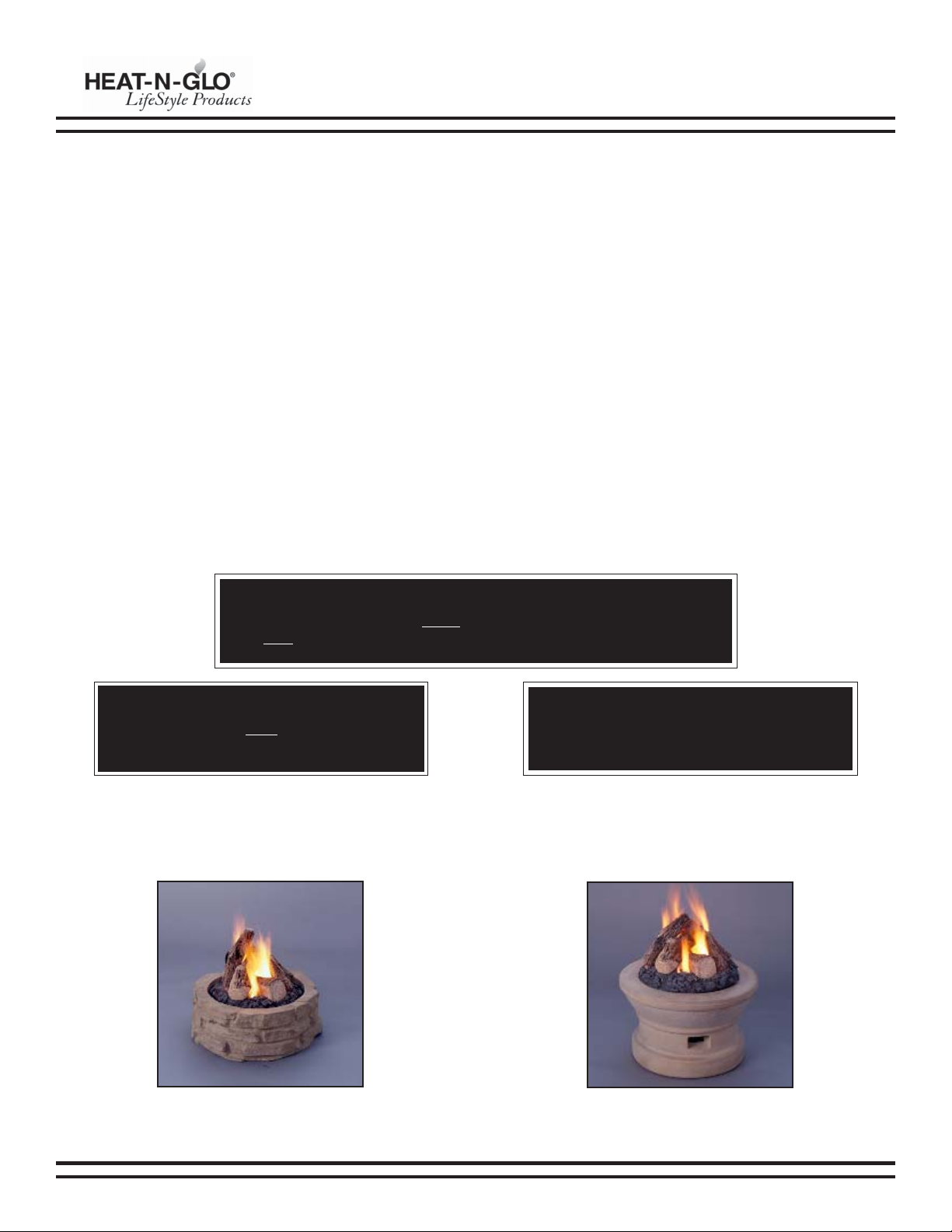
A. INTRODUCTION
This appliance is a Decorative Gas Log Set for OUTDOOR USE ONLY and MUST NOT be used for cooking.
Place this appliance on a flat and stable surface in an outdoor location such as a patio or deck. This location must be adjacent to the
gas supply line or LP gas supply cylinder. DO NOT locate the appliance where it can get excessively wet or submerged in water.
WARNING!
This appliance must be used ONLY outdoors in a well-ventilated space and
must NOT be used inside a building, garage, or any other enclosed area.
WARNING!
This log set must NOT be installed in an
unvented appliance.
WARNING!
This appliance is not for use with solid fuel.
Rock Ring
The following clearances to combustibles must be maintained:
Bottom - 0 in., Sides/Walls (all around) - 24 in. (610 mm), and Top - 8 ft (2.4 m).
A decorative surround can be made from noncombustible material (such as bricks, landscape blocks, rocks, etc.) or two models of
fabricated surrounds are available (see below).
Always keep the appliance area clear and free from combustible materials, gasoline and any other flammable vapors and liquids.
Mesa
CONTENTS
A. Introduction .................................................................................................................................................................. 2
B. Safety Information ......................................................................................................................................................... 3
C. Components and Installation....................................................................................................................................... 4
D. Operating Instructions .................................................................................................................................................. 8
E. Maintenance Instructions ............................................................................................................................................. 9
F. High Elevation Installation ............................................................................................................................................ 9
G. Replacement Parts .................................................................................................................................................... 10
Warranty ...................................................................................................................................................................... 12

08/04 4004-001 Rev C 3
PATIO CAMPFIRE INSTALLATION INSTRUCTIONS
B. SAFETY INFORMATION
The Patio Campfire has been tested in accordance with IAS US
requirements for Outdoor Gas Fireplaces, Draft 4-96 and ANSI
Z21.58-1995/CGA 1.6-M96 for Canada and has been listed by
Underwriters Laboratory (UL) for installation and operation as
described in these installation and operating instructions.
The installation must conform with local codes or, in the absence
of local codes, with the National Fuel Gas Code ANSI Z223.1 or
CAN/CGA-B149.1, National Gas Installation Code or CAN/CGA-
B149.2, Propane Installation Code.
IMPORTANT: Installation of natural gas should be done by a
qualified installer, service agency or gas supplier.
The appliance and its manual shutoff valve must be disconnected
from the gas supply piping system during any pressure testing
of the system at test pressures in excess of 1/2 psig (3.5kPa).
This appliance must be isolated from the gas supply piping
system by closing its manual shutoff valve during any pressure
testing of the gas supply piping system at test pressures equal
to or less than 1/2 psig (3.5kPa).
•Children and adults should be alerted to the hazards of high
surface temperatures and should stay away to avoid burns
or clothing ignition.
•Young children should be carefully supervised when they
are in the area of the appliance.
•Never leave the appliance unattended during operation.
Note: All new LP cylinders (and in many cases used cylinders)
may contain water, air or other contaminants. It is essential
that these substances be released before filling the cylinder
and placing into service. Water vapor present in the gas vapor
may cause the regulator to “freeze up” and cause an
interruption to the gas flow. This interruption will cause the
appliance to shut down. To prevent this from occurring, it is
essential that a qualified individual always purge a new tank
thoroughly before placing it into service. It is recommended
that cylinders that have not been used for extended periods of
time also be purged before use.
•Clothing or other flammable materials should not be placed
on or near the appliance.
•Any guard or other protective device removed for servicing
the appliance must be replaced prior to operating the
appliance.
•Installation and repair should be done by a qualified service
person. The appliance should be inspected before use and
at least annually by a qualified service person. More frequent
cleaning may be required as necessary. It is imperative that
the control compartment, burners and circulating air
passageways of the appliance be kept clean.
•Inspect the fuel supply connection (including the hose for
LP models) before each use of the appliance.
•If it is evident there is excessive abrasion or wear, or the
hose is cut, it must be replaced prior to the appliance being
put into operation.
•The pressure regulator and hose assembly supplied with
LP models must be used. Replacement pressure regulators
and hose assemblies must be those specified in this
manual
•The LP gas supply cylinder used with LP models must be
constructed and marked in accordance with the
specifications for LP gas cylinders of the U.S. Department of
Transportation (DOT).
•Cylinders must be stored outdoors in a well ventilated area
out of the reach of children. Disconnected cylinders must
have threaded valve plugs tightly installed and must not be
stored in a building, garage or any other enclosed area.
•Storage of this appliance indoors is permissible only if it
has been disconnected from its fuel supply (natural gas line
or LP gas cylinder).
•The LP gas cylinder supply system must be arranged for
vapor withdrawal.
•The LP gas cylinder used must include a collar to protect the
cylinder valve.
•When an LP model is not in use, the LP gas must be turned
off at the supply cylinder.
Note: Do not use this appliance if any part has been under
water. Immediately call a qualified service technician to
inspect the appliance and to replace any part of the control
system and any gas control which has been under water.

4 4004-001 Rev C 08/04
PATIO CAMPFIRE INSTALLATION INSTRUCTIONS
C. COMPONENTS AND INSTALLATION
The burner assembly and log assembly are packaged individually and shipped in one carton. See illustrations below.
Burner Assemblies
Log #1 Log #4
Log #2
Log #3
Log Base

08/04 4004-001 Rev C 5
PATIO CAMPFIRE INSTALLATION INSTRUCTIONS
1. Burner Assembly
a. All Models
1) Remove the burner assembly and check for
damage. Do not use damaged components.
2) Position the burner assembly in the desired
location.
This location must be adjacent to the gas supply
line.
You must have easy access to the gas valve control
knob after it is installed and connected the gas
supply because the ON/OFF gas valve is used to
turn the burner on and off.
b. Natural Gas Models
1) Connect the ON/OFF gas valve of the appliance to
the incoming gas supply line. See Figure 1. Make
certain all gas connections are tight.
2) Turn the ON/OFF valve at the appliance slowly to
the “ON” position. All connections must be tightened
and checked for leaks with a commercially
available, non-corrosive leak check solution. Be
sure to rinse off the solution when done leak testing.
c. LP Gas Models
1) Make sure the tank valve is turned completely off
(clockwise).
2) Ensure the tank valve has the proper external mating
threads (tank valve marked “USE WITH TYPE 1”).
3) Inspect the hose shipped with the appliance for
any damage. Do not use if there is evidence of
damage.
4) Connect the end of the hose onto the ON/OFF gas
valve of the appliance. Make sure it is secured tightly.
5) Connect the regulator assembly to the tank valve.
Hand tighten only (clockwise). Do not use a wrench
to tighten! Use of a wrench may damage the quick
closing nut and result in a hazardous condition.
See Figure 2.
6) Position the hose out of pathways where people
might trip over it or in areas where the hose might
be subject to accidental damage.
7) Open the tank valve fully (counterclockwise). Turn
the ON/OFF valve slowly to the “ON” position. All
connections must be tightened and checked for
leaks with a commercially available, non-corrosive
leak check solution. Be sure to rinse off the solution
when done leak testing. If a leak is found, turn the
tank valve off and do not use the appliance until
repairs can be made.
Figure 1
Natural Gas Burner Assembly
Figure 2
Propane Burner Assembly

6 4004-001 Rev C 08/04
PATIO CAMPFIRE INSTALLATION INSTRUCTIONS
2. Enclosures for LP Gas Supply Systems
If you build an enclosure for an LP gas cylinder, follow these recommended specifications and you must follow local codes.
a. Enclosures for LP gas supply cylinders must be ventilated by openings at the level of the cylinder valve and at floor level. The
effectiveness of the opening(s) for purposes of ventilation must be determined with the LP gas supply cylinder(s) in place.
This must be accomplished by one of the following:
1) One side of the enclosure must be completely open or,
2) For an enclosure having four sides, a top and bottom:
•At least two ventilation openings at cylinder valve level shall be provided in the side wall, equally sized, spaced at
180 degrees (3.14 rad), and unobstructed. Each opening must have a total free area of not less than 1/2 square inch
per pound (3.2 sq. cm/kg) of stored fuel capacity and not less than a total free area of 10 square inches (64.5 sq. cm).
•Ventilation opening(s) must be provided at floor level and shall have a total free area of not less than 1/2 square inch
per pound (3.2 sq. cm/kg) of stored fuel capacity and not less than a total free area of 10 square inches (64.5 sq. cm).
If ventilation openings at floor level are in a side wall, there must be a least two openings. The bottom of the
openings must be at floor level and the upper edge can’t be more than 5 in. (127 mm) above the floor. The openings
must be equally sized, spaced at 180 deg (3.14 rad) and unobstructed.
•Every opening must have minimum dimensions to permit the entrance of a 1/8 inch (3.2 mm) diameter rod.
b. Cylinder valves must be readily accessible for hand operation. A door on the enclosure to gain access to the cylinder valves
is acceptable, provided it is non-locking and can be opened without the use of tools.
c. There must be a minimum clearance of 2 in. (50.8 mm) between the lower surface of the floor of the LP gas supply cylinder
enclosure and the ground.
d. The design of the enclosure must be such that:
1) The LP gas supply cylinder(s) can be connected, disconnected and the connections inspected and tested outside the
cylinder enclosure.
2) Those connections which could be disturbed when installing the cylinder(s) in the enclosure can be leak tested inside
the enclosure.
3) Be certain to mount or set the LP gas cylinder on a flat stable surface and retain it to prevent it from tipping.
e. Purge the gas supply line of any trapped air prior to the first firing of the appliance!
WARNING!
Due to the initial purging and subsequent lightings, NEVER allow the gas valve to remain in the “OPEN” position
without first placing a burning match on the top of the burner.
08/04 4004-001 Rev C 7
PATIO CAMPFIRE INSTALLATION INSTRUCTIONS
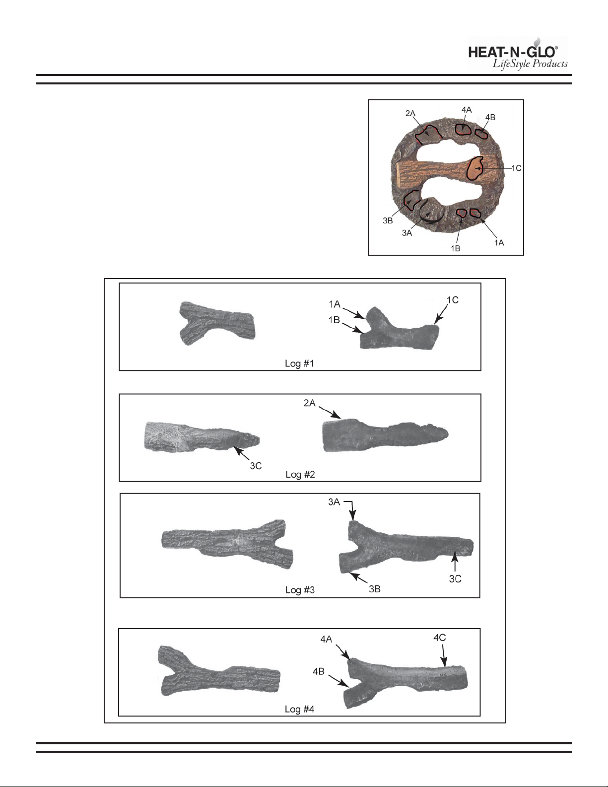
3. Log Assembly
a. Check all logs and the log base for any damage. Do not
use damaged or broken components!
b. Position the log base over the burner making sure to
align the dimple in the log base over the locating button
on the burner top (see burner assemblies, page 4).
c. Position the logs by placing the corresponding
letter/number combinations located on the logs
(Figure 4) with those on the log base (Figure 3).
Figure 3 - Log Base (top view)
Figure 4
8 4004-001 Rev C 08/04
PATIO CAMPFIRE INSTALLATION INSTRUCTIONS
D. OPERATING INSTRUCTIONS
Inspect the burner before each use of the appliance. If there is any evidence that the burner is damaged, it must be replaced before
operating. See the Replacement Parts list on page 11.
Upon completing the gas line connection, a small amount of air will be in the lines. When first lighting the burner, it will take a few
minutes for the lines to purge themselves of this air. Subsequent lighting of the appliance will not require such purging. Never allow
the ON/OFF valve to remain in the open position without placing a burning match on top of the burner FIRST!
FOR YOUR SAFETY, READ BEFORE LIGHTING
WARNING!
If you do not follow these instructions exactly, a fire or explosion may result causing property damage,
personal injury and/or loss of life.
A. This appliance must be lit by hand. When lighting, follow
these instructions exactly.
B. Before lighting, smell all around the appliance area for
gas. Be sure to smell next to the base of the appliance
because some gas is heavier that air and will settle on
the floor.
WHAT TO DO IF YOU SMELL GAS:
•Do not try to light any appliance.
•Do not touch any electric switch; do not use any phone in
your building.
•Immediately call your gas supplier from a neighbor’s
phone. Follow the gas supplier’s instructions.
•If you cannot reach your gas supplier, call the fire
department.
C. Use only your hand to turn the gas control knob or valve.
Never use tools. If the valve will not turn by hand, don’t try
to repair it, call a qualified service technician. Force or
attempted repair may result in a fire or explosion.
D. Do not use the appliance if any part has been under
water. Immediately call a qualified service technician to
inspect the appliance, and to replace any part which has
been under water.
Turn the ON/OFF valve to the “OFF” position at the appliance for a natural gas appliance.
For an LP appliance, turn the ON/OFF valve to the “OFF” position at the appliance and then turn the valve on the LP tank
clockwise to the “OFF” position.
TO TURN OFF GAS TO APPLIANCE
1. Stop! Read the safety information above.
2. Remove the cover.
3. Find the manual gas control valve.
4. Place a burning match on top of the burner in the middle
where ports are present. DO NOT HOLD THE MATCH IN
YOUR HAND! For a natural gas appliance turn on the ON/
OFF valve slowly at the appliance. For an LP appliance
turn the valve on the LP tank counterclockwise all the way
and then turn on the ON/OFF valve slowly at the appliance.
5. If the burner does not light before the match goes out,
immediately turn the gas valve to “OFF”.
6. Wait at least five minutes to clear out any gas. Then smell
for gas, including the base of the appliance. If you smell
gas, STOP! Follow “B” in the safety information above. If
you do not smell gas, repeat Step 4.
LIGHTING INSTRUCTIONS

08/04 4004-001 Rev C 9
PATIO CAMPFIRE INSTALLATION INSTRUCTIONS
E. MAINTENANCE INSTRUCTIONS
1. The appliance should be inspected before initial use and
inspected and cleaned at least annually by a qualified field
service person.
2. Tampering with this appliance is DANGEROUS and voids all
warranties. Any component that is found to be faulty must be
replaced with an approved component.
3. To obtain proper operation, it is imperative that the burner
flame characteristics are steady, not lifting or floating. Check
the burner flame patterns with Figure 5.
4. Periodically remove the logs and examine the burner. If dirty,
clean with a soft brush. Also examine the area around the
burner air shutter. Any dirt or lint in this area should be
removed. This will ensure long life and trouble free operation.
When the appliance is put back in service, check the burner
flame patterns with Figure 5. Reinstall the logs as shown in
the log placement instructions.
5. Periodically check the hose connecting the LP gas cylinder
to ensure it is not damaged in any way.
Figure 5 - Flame Patterns
Note: Carbon (soot) may build up on the surfaces of the
logs with heavy use. This is more likely to occur when using
LP gas. The soot should be cleaned off the surface of the
logs periodically to prevent excessive buildup.
To clean the logs, be sure the fire is out, the gas supply is
turned off and the logs are cool to the touch. The soot can
then be brushed off with a dry bristle brush or cloth. Take
care while cleaning the logs as they can become damaged
if mishandled. Care should be taken to dispose of the soot
and cleaning materials properly. Keep away from clothing
and outdoor furniture.
F. HIGH ELEVATION INSTALLATION
For U.S. installation, this appliance is tested and approved for elevations from 0-2000 ft. When installing this appliance at an elevation
above 2000 ft, National Fuel Gas Codes require a decrease of the input rating by changing the existing burner orifice to a smaller size.
Input should be reduced 4% for each 1000 ft above sea level. Check with the local gas utility for proper orifice size identification.
For Canada, this appliance is certified for elevations from 0-4500 ft. When installing this appliance at an elevation between 0-4500 ft
in Canada, the input rating does not need to be reduced. When installing this appliance at an elevation above 4500 ft in Canada,
check with local authorities.
ORIFICE SIZES
Fuel Orifice # Orifice Size Maximum Output
Propane Gas #44 .086 60,000 BTUs/hr
Natural Gas #27 .144 75,000 BTUs/hr
10 4004-001 Rev C 08/04
PATIO CAMPFIRE INSTALLATION INSTRUCTIONS
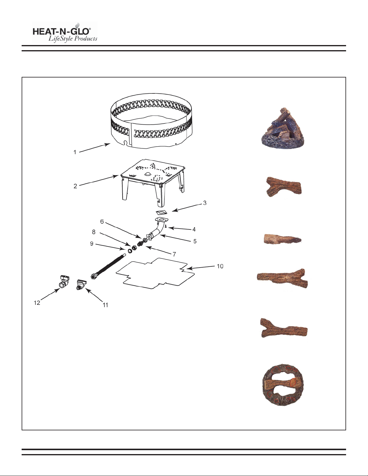
G. REPLACEMENT PARTS
Log Assembly
Log #1
Log #2
Log #3
Log #4
Log Base
08/04 4004-001 Rev C 11
PATIO CAMPFIRE INSTALLATION INSTRUCTIONS
REPLACEMENT PARTS (con’t)
# Description of Part PCF-HNG Qty. R
Log Assembly 34382 1 Y
Log Base 34387 1 Y
Log #1 34383 1 Y
Log #2 34384 1 Y
Log #3 34385 1 Y
Log #4 34386 1 Y
# Description of Part PCF-HNG Qty. R
1Ring 35272 1 Y
2 Burner Assembly 35323 1 Y
3 Burner Weldment 35324 1 N
3 Burner Neck Gasket 17196 1 N
4 SMS #8x1/2 S-Grip BO 12460 2 Y
5 Burner Neck Assembly 34465 1 Y
Natural Gas Flex Tube Assembly 35326 1 Y
LP Gas Flex Tube Assembly 33452 1 Y
6 Jam Nut 32563 1 Y
7 Orifice - NG (#27) 35321 1 Y
7 Orifice - LP (803-803) 32562 1 Y
8 Compression Nut 32553 1 Y
9 Flex Grommet 477-825 1 N
10 Heat Shield 35271 1 N
11 Ball Valve (LP) 477-311 1 N
12 On/Off Valve (NG) 15697 1 Y
Hose / Regulator Assy (LP) 4004-014 1 Y

12 4004-001 Rev C 08/04
Hearth & Home Technologies Inc.
Outdoor Products Limited One Year Warranty
Hearth & Home Technologies Inc. extends the following warranty for Hearth & Home Technologies outdoor products used in
the United States of America or Canada. Dealers and employees of Hearth & Home Technologies have no authority to make
any warranty or authorize any remedies in addition to or inconsistent with the terms of this warranty. This warranty gives you
specific legal rights. You may also have other rights that vary from state to state.
Hearth & Home Technologies warrants that this Hearth & Home Technologies Outdoor Product (the “Product”) will be free
from defects in material and workmanship for a period of one year from its date of purchase. This warranty is subject to the
conditions, exclusions and limitations described below.
This warranty applies only to the original owner of the Product and is non-transferable. Hearth & Home Technologies’
obligation under this warranty does not extend to damages resulting from (1) assembly, operation or maintenance of the
Product not in accordance with the Installation/Assembly Instructions, Operating Instructions and the Listing Agency Identification
Label furnished with the Product; (2) installation or use which does not comply with local building codes and ordinances; (3)
shipping, improper handling, improper operation, abuse, misuse, accident or unworkmanlike repairs; (4) use of fuels other
than those specified in the Operating Instructions; (5) Installation or use of components not supplied with the Product or any
other components not expressly authorized and approved in writing by Hearth & Home Technologies; and/or (6) modification
of the Product not expressly authorized and approved in writing by Hearth & Home Technologies. Any of the circumstances
described in the previous sentence voids this warranty. This warranty is void if the Product or any component has been
removed, repaired, or replaced before Hearth & Home Technologies has been afforded a reasonable opportunity to inspect
the Product.
This warranty is limited to the replacement or repair of defective components or workmanship and Hearth & Home Technologies
may fully discharge its obligations under this warranty by repairing or replacing, at its discretion, the defective components.
Hearth & Home Technologies will provide replacement parts at no charge and will pay reasonable and necessary labor and
freight costs related to replacing or repairing defective components under this warranty. The maximum amount recoverable
under this warranty is limited to the purchase price of the Product and, if Hearth & Home Technologies is unable to provide
replacement or repair in an expedient and cost-effective manner, Hearth & Home Technologies may discharge all obligations
under this warranty by refunding the purchase price of the Product.
EXCEPT TO THE EXTENT PROVIDED BY LAW, HEARTH & HOME TECHNOLOGIES MAKES NO EXPRESS WARRANTIES
OTHER THAN THE WARRANTY EXPRESSED HEREIN. THE DURATION OF ANY IMPLIED WARRANTY IS LIMITED TO THE
DURATION OF THE WARRANTY SPECIFIED ABOVE. IN NO EVENT SHALL HEARTH & HOME TECHNOLOGIES BE LIABLE
FOR ANY INCIDENTAL OR CONSEQUENTIAL DAMAGES CAUSED BY DEFECTS IN THE PRODUCT. Some states do not
allow limitations on how long an implied warranty lasts, or do not allow exclusion or limitation of incidental or consequential
damages, so these limitations may not apply to you.
To obtain service under this warranty, you must:
1. Send written notice of the claimed condition to: The Technical Services Department, Hearth & Home Technologies Inc.,
Mt. Pleasant, 1915 W. Saunders St., Mt. Pleasant, IA 52641 (phone: 1-800-927-6841).
2. Affirm that you are the original owner of the Product.
3. Provide Hearth & Home Technologies reasonable opportunity to investigate the claim, including reasonable opportunity
to inspect the Product prior to any repair or replacement work and before the Product or any component of the Product has
been removed.
4. Obtain Hearth & Home Technologies’ consent to any warranty work before the work is done.
© 2004 Hearth & Home Technologies Inc. 803-905 8/04
Table of contents
Popular Patio Heater manuals by other brands

Comfortaire
Comfortaire IRPH15SS Comfort Aire Installation & operation manual

Comfort Zone
Comfort Zone CZPH10 Series instructions

Firesense
Firesense Patio Heater instruction manual

Ener-G+
Ener-G+ HEA-21590BT instruction manual

Firesense
Firesense LIP-10A-TGG-LPG-BU user manual

Hotspot
Hotspot Spiral user guide


