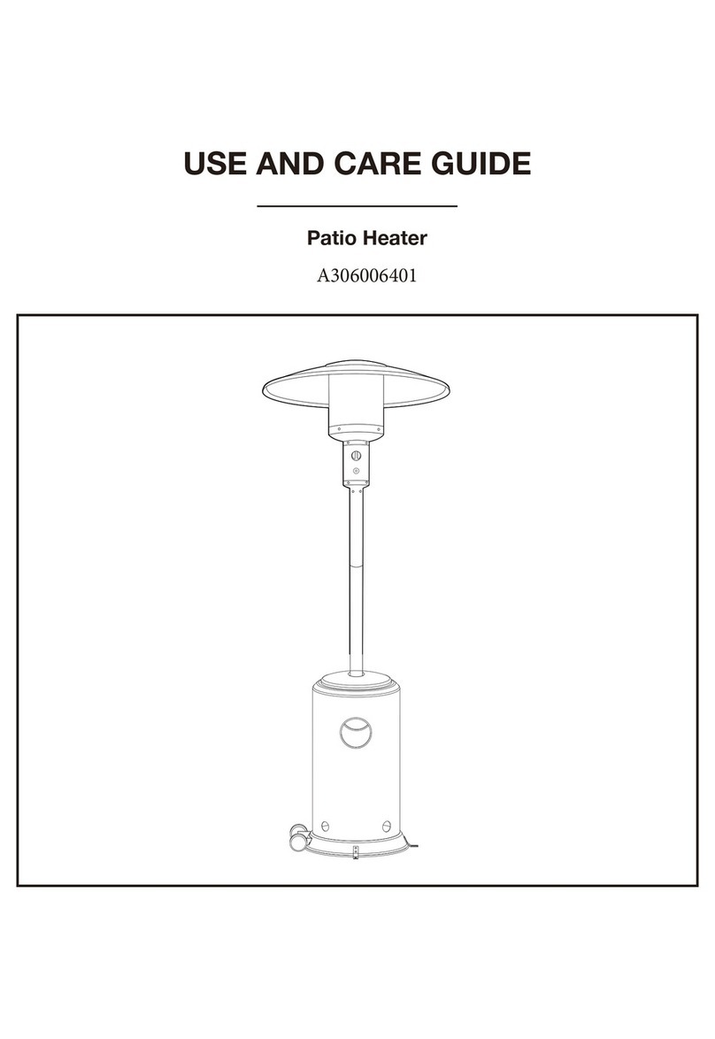
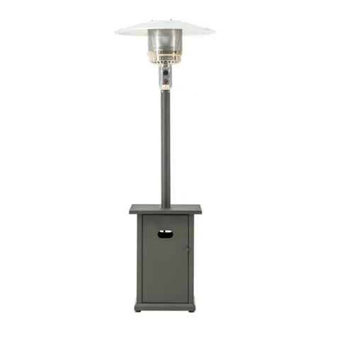
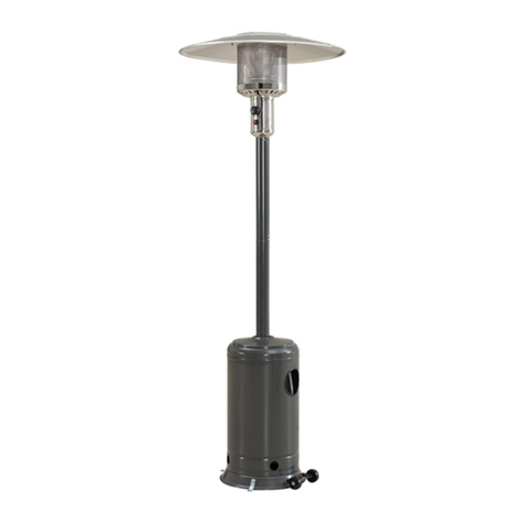
Sunjoy L-PH011PSS-2 User manual

1
Owner’s Manual
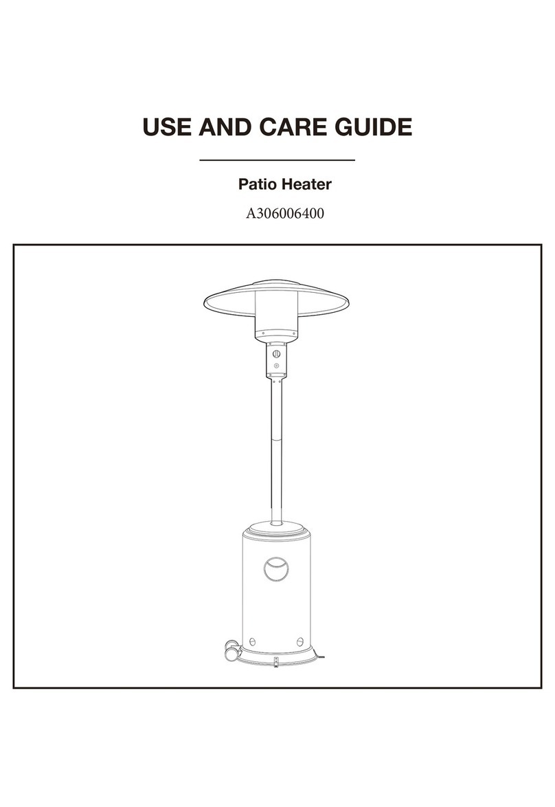
Stainless Steel Patio Heater —L-PH011PSS-2
Propane tank not included
1 AAA battery included
Standard: ANSI Z83.26a-2008/CSA 2.37a-2008, Gas-Fired Outdoor Infrared Patio Heater
Questions, problems, missing parts? Before returning to your retailer, call our customer service
department at 1(866) 578-6569 from 8:30 AM to 5:30 PM EST , Monday-Friday .
Warning: For Outdoor Use Only
Warning: For your safety
Chemical known to the State Of California to cause
cancer, birth defects, or other reproductive harm
are created by the Combustion of Propane.
Warning: For your safety.
If you smell gas:
1. Shut off gas to the appliance.
2. Extinguish any open flame.
3. If odor continues, immediately call your gas
su
pp
lier or local fire de
p
artment.
Warning: For your safety
Failure to follow the manual’s warning and
instructions can result in severe personal injury,
death, or
p
ro
p
ert
y
dama
g
e.
Warning: For your safety
Improper installation, adjustment, alteration,
services or maintenance can cause injury or
property damage. Read the installation, operation
and maintenance instructions thoroughly before
installing, operating or servicing this equipment.
Warning: Do not store or use gasoline or
other flammable Vapors and liquids in the vicinity
of this or any other appliance.
An LP-cylinder not connected for use shall not be
stored in the vicinity of this or any other appliance.

2
Table of Contents
Specification …………………………………………………………………………
Introduction ………………………………………………………………………
1. Safety Information ………………………………………………………………….
2. Parts Identification ……………………………………………………………. ….
2.1. Tools required ………………………………………………….. …………
2.2. Components / Hardware Bag…………………………………………….
3. Assembly Instructions………………………………………………………………
Step 1. Attach Left and Right Shrouds to Base
Step 2: Attach Front Shroud
Step 3: Assemble the door handle
Step 4: Assemble the Pin
Step 5: Install Gas Tank Protecting Wire
Step 6: Attach the door to the base
Step 7: Attach Back Shroud
Step 8: Attach Gas Tank Top Fence
Step 9: Attach Pole to Top Fence
Step 10: Attach the tabletop to the pole
Step 11: Attach the Engine to the Pole
Step 12: Attach Dome to Engine
Step 13: Fit Cylinder to the shroud
Step 14: Check for Leak
4. Operation …………………………………………………………………………. ….
4.1. Preparation before lighting…………………………………………………
4.2. Check Connection at Regulator/Cylinder for leaks ………………. ….
4.3. Check and ensure the control knob is in the OFF position…………….
4.4. Purging the Pilot……………………………………………………………..
4.5. Lighting the Pilot……………………………………………………………..
4.6. Heat Setting Control…………………………………………………………..
4.7. Turn off …………………………………………………………………………
5. Storage ………………………………………………………………………………
6. Maintenance ………………………………………………………………………..
7. Troubleshooting.…………………………………………………………………….
8. Service ………………………………………………………………………………
9. Warranty Term…………………………………………………………………………
3
3
3-4
4
4
4-5
5
5
5
6
6
6
7
7
7
8
8
8
9
9
9-10
10
10
10
10
10
10-11
11
11
11
12
12
13
13
IMPORTANT
Please take time to read these instructions thoroughly and follow each step carefully for
safe and easy operation. Keep this manual for future reference.
Please do not return this product to the store. For technical assistance on assembly or
replacement parts call Sunjoy Industries at 1(866) 578-6569 from 8:30 AM to 5:30 PM EST or

3
Specifications
Introduction
Thank you for choosing the Sunjoy Patio Heater as your form of outdoor heating.
Please take time to read these instructions thoroughly and follow each step carefully for safe and easy
operation. Keep this manual for future reference. Please do not return this product to the store. For
technical assistance on assembly or replacement parts call Sunjoy Industries at 1(866) 578-6569 from
1. Safety Information
To ensure safe use of your patio heater, you are requested to pay close attention to these essential
safety requirements.
Certain items or material (mainly flammables and combustibles), when stored under the heater or nearby will
be subjected to radiant heat and could be seriously damaged.
Always place heater on a firm and level surface.
Always keep at least 16” (40 cm) clearance from any combustible materials.
Always keep at least 39.4” (1m) clearance around air opening into the combustion chamber.
Do not use if the wind velocity is greater than 10 mph.
Do not use if the air temperature is below 40 degrees Fahrenheit.
Do not hang clothing or flammable materials either on or near heater.
Do not spray aerosols near the heater while in use.
Do not touch the heater while in use.
Bystanders should be alerted to the hazards of high surface temperatures and stay far enough away to avoid
burns or clothing ignition.
Your children and pets should be supervised when they are in area of heater.
Do not alter or modify the heater in any manner.
Use the specified gas type only – Propane/ LP Gas.
When conducting leak tests, only use soapy water at the cylinder connection, while looking for possible
bubbles.
Place the control knob on OFF position when heater is not in use.
Allow 45 minutes to cool down after use before attempting to move your heater.
Gas supply must be turned off at the supply cylinder while not in use.
Do not clean heater with combustible or corrosive cleaners. Use warm soapy water.
Inspect heater before each use and inspect annually by a qualified service person.
This appliance must only be used outdoors in a well ventilated area, and not to be used in a garage or any
other enclosed building.
Guards or other protective devices removed for servicing must be replaced prior to operating.
The cylinder used must include a collar to protect the cylinder valve.
Frequent cleaning is necessary. Control compartment, burners and circulating air passageways must be kept
clean.
Use only the pressure regulator and hose assembly supplied by manufacturer.
Pls. use on level ground. Do not use on slope larger than 15°.
Do not Store a spare gas cylinder under or near this appliance
Never fill the cylinder beyond 80 percent full.
For appliance designed to use CGA NO.791 connection : Place the dust cap on the cylinder valve outlet
Certification CSA
Rated Heat Output 40,000 Btu/Hr
Fuel Propane-LP
Gas Supply 20 lb. LP-Gas cylinder
Manifold Pressure 11 inches W.C
Injector Size (diameter) 1.95 mm
Safety Features Flame failure device, Tilt switch
Gas Supply Pressure Max. 150 PSI, Min 5 PSI
4
whenever the cylinder is not in use, only install the type of dust cap on the cylinder valve that is provided
with cylinder valve, other types of caps or plugs may result in leakage of propane.
2. Parts Identification
2.1 Tools required: wrench, Magnetic Head Phillips Screwdriver
2.2 Components / Hardware Bag Hardware Bag includes:
OFF
Pilot
HIGH
LOW
A Dome
B Engine
C Pole
D Table Top
E Front shroud
F Right shroud
K Left shroud
G Handle
H Door
L Back shroud
M Rack
J Regulator
I Base
N WEIGHT
O Gas tank protecting wire
Part List
code name Qty Picture
A Dome 1
B Engine 1
C Pole 1
D Table top 1
E Front shroud 1
F Right shroud 1
G Handle(include 2
rubber caps ) 1
H Door 1
Picture Code Name Qty Used
in
Steps
H1 Bolt 8 8, 9
H2 Bolt 3 11
H3 Bolt 2 3
H4 Self-drilling
screw 8 2, 7
H5 Self-drilling
screw 4 10
H6 Acorn Nut 3 12
H7 Lock washer 4 1
H8 Lock washer 8 8, 9
H9 Nut 4 1
H10 Pin 1 4
OFF
Pilot
HIGH
LOW

5
I Base 1
J regulator 1
K Left shroud 1
L Back shroud 1
M Rack 1
N Weight(wheels are
pre-assembled)1
O gas tank protecting
wire 1
3. Assembly Instructions
(Please refer to below Diagrams)
1
H7
H9
QTY.4
QTY.4
2
QTY.4
H4
TIP: Please check above components and hardware before assembling.
Step 1. Attach Left and Right Shrouds to Base
Align the bolts on the left and right shrouds to the
screw holes on the base.
Secure the left shroud and right shroud, base and
the weight, using 4 Lock washers (H7) and 4 Nuts
(H9).
Step 2. Attach Front Shroud
Attach the front shroud to the left and right
shrouds with 4 self-drilling screws (H4).

6
3
QTY.2
H3
5
Step 3. Assemble the door handle
Attach the door handle to the door, using 2 Bolts
(H3).
Insert 2 rubber caps into the holes inside of the door.
4
Step 4. Assemble the Pin
Fasten the pin (H10) to the base.
Step 5. Install Gas Tank Protecting Wire
Turn the gas tank protecting wire to the correct
direction. Lock each end of the wire into the slots on
the edge of left and right shrouds.
This wire can prevent the gas tank from shaking.
H10

7
6
QTY.4
7
H4
8
QTY.4
QTY.4
H1
H8
Step 6. Attach the door to the base
Fix the door hinge on the base. Line up the hole at
the left bottom of the door with the hinge. Place the
door onto the hinge.
Line up the hold at the right top of the door with the
door pin. Insert the door pin into this hole.
Step 7. Attach Back Shroud
Attach the back shroud to the left and right shrouds
using 4 Self-drilling screws (H4).
Step 8. Attach Gas Tank Top Fence
Attach the Rack fence to the beams of the left and
right shrouds using 4 Bolts (H1) and 4 lock washers
(H8).

8
9
H1
H8 QTY.4
QTY.4
Qty.3
OFF
Pilot
HIGH
LOW
H2
Step 9. Attach Pole to Top Fence
Fix the pole on the top fence with 4 Bolts (H1), 4 Lock
washers (H8).
Make sure Pole is perpendicular to Base.
Note: The pole must be perpendicular to Base. Failure
to do so will adversely affect burner performance.
QTY.4
H5
10 Step 10. Attach the tabletop to the pole
Fix tabletop with pole by using 4 Self-drilling screws
(H5).
Step 11. Attach the Engine to the Pole
Align the 3 holes on the top pole with three holes on
the bottom of Engine. Attach them by using 3 Bolts
(H2).
Ensure they are fully tightened.
Install the switching knob on the housing of the switch
control panel.
11

9
Qty.3
H6
12
Step 14. Check for leak
Make 2-3 oz. of leak check solution by mixing one part liquid dishwashing soap and three parts water.
A. Turn cylinder valve ON
Check Gas Line/Control Valve for leaks.
Spoon several drops of solution onto Gas line and Control valve connection.
Inspect the solution at the connection to look for bubbles.
If NO bubbles appear, then the connection is secure. If bubbles appear, there is a leak.
B. Turn cylinder valve OFF
Loosen screw on Clip.
Release gas line fitting from control valve and re-attach making sure connection is secure.
Re-tighten Clip.
Step 12. Attach Dome to Engine
Align holes in Dome with threaded studs on the top of
Engine.
Secure Dome to Engine with 3 Acorn Nuts (H6).
Step 13. Fit cylinder to the shroud
Put the cylinder into the shroud, and then block it by the
fixture

10
OFF
Pilot
HIGH
LOW
The installation must conform with local building codes, or in absence of local codes, the
National Fuel Gas Code, ANSIZ223.1.
4. Operation
4.1. Preparation before lighting
Make sure Control Knob is at OFF position.
4.2. Check Connection at Regulator/Cylinder for leaks. (See Figure 3)
4.3. Check and ensure the control knob is in the OFF position.
Place the Gas cylinder inside the Cylinder Cabinet and connect the Regulator to the Gas cylinder.
(see Figure 1)
Turn the Cylinder valve on. Apply a dishwashing soap and
water solution to the connection at Regulator and Cylinder. (See Figure 3)
If the connection is leaking you will see bubbles form.
In the case of any leaks, turn off the gas supply, undo the leaking connection, re-connect and try
again. If the leak persists consult Sunjoy Industries Customer Service 1 (866) 578 6569 for
assistance and advice.
Do not use an open flame to test for leaks.
Once the testing is complete and there is no sign of a leak, continue the next step.
4.4. Purging the Pilot
To light the pilot the first step is to purge the gas line leading to the pilot assembly.
Press and turn the control knob to PILOT position and keep it depressed in for 1 to 2 minutes, then
conduct next step-light Pilot immediately. (see Figure 4)
Note: When a new or refilled gas cylinder is installed or the control knob
is turned on, the heater will need to have the Air purged out of the system.
4.5. Lighting the Pilot (see Figure 4)
Insert the Battery into the igniter button.
Press the control knob and turn to the PILOT position.
Hold the control knob in and press the igniter button until the Pilot lights.
Keep the control knob depressed in for a minute to heat the thermocouple.
Release the control knob and the Pilot should stay alight. If it does not, then try
re-lighting.
Note: To visually check the ignition of the Pilot, slide the viewing hole cover in Engine (B) to
either side. Once the Pilot flame stays on, close this cover.
Caution: Do not attempt to slide the Viewing hole cover when the Main burner is lit.
Lighting Instruction
a. Turn the LP gas tank valve OFF. Push control konb in , turn OFF,
And wait 5 minutes for any gas to clear.
Igniter Button
(Figure 4)

11
b. Turn the tank valve ON, push control
knob in and rotate to PILOT
Then push the igniter button until the
burner is ignited. If the burner
fails to remain lit or becomes
extinguished, repeat step b.
c. Once the burner has lit, continue to hold
the control knob in for 10
seconds, then release.
d. Turn the control knob from LOW to
HIGH to the desired heat setting.
4.6. Heat Setting Control (See Figure 4)
Press and turn the control knob to HIGH position, the burner will light immediately.
Press and turn the control knob to the heat setting required.
Note: While in use, the burner flame should be mainly blue in appearance with a small amount of
Yellow. Consult your store of purchase if satisfactory performance cannot be obtained.
Warning: If you smell gas while in use, immediately press and turn the control knob to “OFF”
position to shutdown the heater.
4.7. Turn off (See Figure 4)
Press and turn the control knob to PILOT position, the burner will extinguish but the Pilot will stay on.
To extinguish the Pilot, press and turn the control knob to OFF position.
Turn off the gas supply.
NOTE: Be careful not to bend the flexible hose part of the regulator. If the hose is bent, gas flow
could be reduced, or a gas leak could occur.
Please put the hose part of the regulator in proper and safe place. Keep it out of the pathways
where people may trip it over or in areas where the hose may be subjected to accidental damage.
Inspect the visible hose portion of the regulator prior to each use. Check it completely at least
annually.
Important: Use only standard 20 lbs propane cylinder constructed and marked in
accordance with the specifications for LP-gas cylinder of the U.S. Department Of
Transportation (D.O.T.). Disconnect the cylinder when the appliance is not in use.
5. Storage
Allow at least 45 minutes for the heater to cool down after using.
Store the Gas cylinder in a cool, dry and well ventilated area, out of the reach of children, and not in
a building, garage or any other enclosed area.
Store the heater upright in a sheltered area away from inclement weather and dust.
When the Patio Heater is completely cool, then the provided cover can be used.
Storage indoors is permissible only if the cylinder is removed.

12
6. Maintenance
To obtain the best performance from your heater make sure you perform the following maintenance
activities on a regular basis:
Keep exterior surfaces clean. Use warm soapy water for cleaning. Never use flammable or
corrosive cleaning agents. Be sure to keep the area around the burner and control assembly dry at all
times.
Airflow must be unobstructed. Clear insect nests or webs away from your heater’s exterior and
interior.
Carbon deposits may create a fire hazard. Clean dome and emitter with warm soapy water if
required.
Check your heater for signs of damage or wear, and replace components as necessary.
Check the hose located within the confines of the enclosure.
Keep the appliance area clear and free from combustible materials, gasoline and other
flammable vapors and liquids.
Keep the ventilation openings of the cylinder enclosure free and clear from debris.
Visually check the burner flame with below pictorial representations.
1) Flame should be blue with slight yellow tips.
2) Light burner, rotate knob from HIGH to LOW. You should see a
smaller flame in LOW Position than seen on HIGH. Always check
flame prior to each use. If only low flame is seen, refer to
“Burner flame is low” in the Troubleshooting Section.
7. Troubleshooting
PROBLEM WHAT TO DO?
Pilot won’t light Does the gas Cylinder contain gas?
Check the Gas supply-Is it connected and /or turned ON?
Is the correct gas type connected?
Has the Pilot line been purged as shown in the Purging section?
Check if the spark igniter is working. To do this, look through the viewing
hole. If you can’t see the spark, you may use a lighted match.
The Pilot jet may be blocked.
Check the Gas Pressure.
Pilot goes out Thermocouple, which is incorporated into part B, may need replacing.
The Pilot jet may be partially blocked.
Burner won’t light Is the Pilot light still burning?
The Burner jet may be blocked.
The Gas Cylinder may be low on gas.
Check the Gas Pressure.
Burner flame is low The Gas Cylinder may be low on gas.
Is the Control Knob positioned at “HIGH”?
The Burner jet may be partially blocked.
Check the Gas Pressure.
Burner emits smoke The Burner will burn off oily materials when it’s first lit.
Persistent smoke could suggest a partial blockage within the Burner itself.
Carbon deposit on Build-up of carbon can accumulate over time. Wipe off before lighting.

13
Emitter and dome
8. Service
Please do not return this product to the store. For technical assistance on assembly or replacement
parts call Sunjoy Industries at 1(866) 578-6569 from 8:30 AM to 5:30 PM EST or Email
Warning:
Use original equipment replacement parts only. Use of unauthorized parts or
modification of parts can void warranty and create an unsafe condition.
9. Warranty Term
Subject to the conditions set out below, this product is warranted to the original purchaser to be free
from defects in workmanship and materials for 12 months from the date of purchase.
9.1 Satisfactory proof of the purchase date must be furnished at the time of notification of the defect for
any claim under the warranty to be enforceable.
9.2 This warranty covers all parts found defective in workmanship and/or materials during the warranty
period and can be repaired or replaced at the discretion of the manufacturer at no cost to the original
purchaser.
9.3 This warranty will be void and accordingly no claim of any nature will be enforceable if the product
has not been assembled, installed or operated according to the instructions, subjected to abuse,
improperly treated, neglected, rusted by exposure to the elements, misused and/or if any repairs,
maintenance, or service has been done by an unauthorized person.
9.4 Returns must be properly packaged and freight prepaid to the dealer from whom the product was
acquired.
9.5 Each of the manufacturer, distributor and retailer will not be liable for any incidental or consequential
loss or damage arising from the installation or operation of the product and/or the failure of any part
for any reason.
9.6 There are no other express or implied warranties, except for those stipulated herein. This warranty
gives specific rights and the original purchaser may have additional rights and remedies in law.
9.7 This warranty does not cover commercial use.
Sunjoy Industries Group Inc.
Add: 619 Slack Street
Steubenville, Ohio 43952, USA
Tel: 1-866-578-6569
AllRightsreserved
Table of contents
Other Sunjoy Patio Heater manuals

Sunjoy
Sunjoy A306004300 User manual

Sunjoy
Sunjoy A30600640 User manual

Sunjoy
Sunjoy AMBERCOVE A306007500 User manual

Sunjoy
Sunjoy A306006400 User manual

Sunjoy
Sunjoy A306006403 User manual

Sunjoy
Sunjoy A306006402 User manual

Sunjoy
Sunjoy AMBERCOVE A306007400 User manual

Sunjoy
Sunjoy L-PH004PCA User manual

Sunjoy
Sunjoy L-PH004PCA User manual

Sunjoy
Sunjoy L-PH004PCA User manual