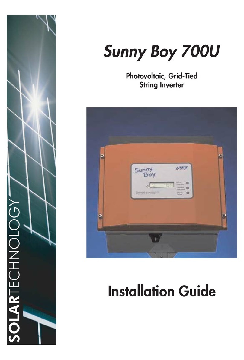
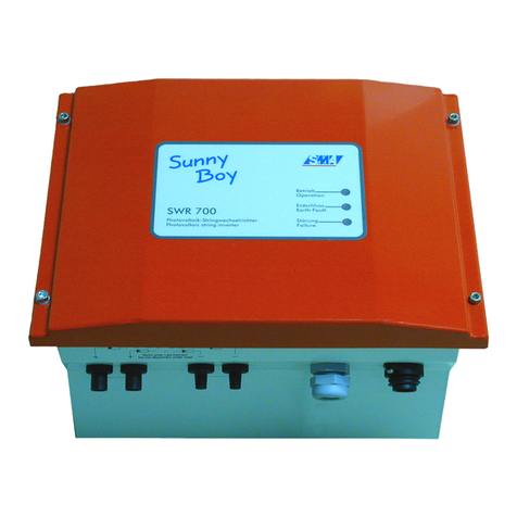
Sunny Boy 700 Parts list manual

SB700-11:EE0502
String Inverter for Photovoltaic Plants
Issue 1.0
Technical Description
Sunny Boy 700

Sunny Boy 700 Technical Description
SB700-11:EE - 2- SMA Regelsysteme GmbH
Alteration Review
Document
Number
SB700
Issue
and Alteration
Review 1)
Comments Author
-11:EE0502 1.0 A Translation from German Issue 1.0 Simon
1) A: Changes due to faulty documents or improvement of the documentation
B: Changes maintaining full or upward compatibility
C: Changes limiting or excluding compatibility
Name Date Signature
Approved Bremicker

Sunny Boy 700 Technical Description
SB700-11:EE - 3- SMA Regelsysteme GmbH
Explanation of Symbols used in this Document
To enable optimal usage of this manual and safe operation of the device during in-
stallation, operation and maintenance routines, please note the following description
of symbols:
This indicates a feature that is important either for optimal and comfortable
usage or optimal operation of the system.
Example: “To keep string voltage low we recommend the following proce-
dure.”
This indicates a fact or feature which is very important for the safety of the
user and / or which can cause a serious defect if not applied appropriately.
Example: ”Disconnect the mains plug before opening the case!“
This indicates an example.

Sunny Boy 700 Technical Description
SB700-11:EE - 4- SMA Regelsysteme GmbH
Table of Contents
1Introduction..........................................................................................................6
2System Description..............................................................................................7
2.1 String Technology.......................................................................................8
2.2 Diagnosis and Communication.................................................................10
2.3 Technical design of the Sunny Boy 700....................................................11
3Installation.........................................................................................................16
3.1 What must be done in case of transport damages? .................................16
3.2 Placement of the Sunny Boy.....................................................................17
3.3 Electric Connection...................................................................................22
3.3.1 Connection to the Electricity Grid.........................................................23
3.3.2 Connection of the PV-panels................................................................25
4Commissioning..................................................................................................30
5Operation and Failure Indication LEDs..............................................................32
5.1 Opening and closing of the Sunny Boy.....................................................46
6System Monitoring and Diagnosis.....................................................................49
6.1 Data Transmission via Powerline..............................................................49
6.2 Data Transmission with a Separate Data Cable.......................................51
6.3 Upgrading or modification of the Sunny Boy interface..............................59
6.4 Graphic User Interface under Windows....................................................62
6.5 Measuring Channels and Messages of the Sunny Boy............................64
6.6 Measurement Precision............................................................................67
7Troubleshooting.................................................................................................68
8Warranty Regulations and Liability....................................................................70
9Technical Data ..................................................................................................72
10 Appendix ...........................................................................................................80

Sunny Boy 700 Technical Description
SB700-11:EE - 5- SMA Regelsysteme GmbH
Important Safety Notice:
The Sunny Boy String Inverter may only be opened by qualified per-
sonnel for both maintenance and modification.
The device can still be charged with very high hazardous voltages
even when disconnected.
For optimal safety closely follow all steps as described in the chap-
ters 3, “Installation” and 5.1, “Opening and closing of the Sunny
Boy”.

Sunny Boy 700 Technical Description
SB700-11:EE - 6- SMA Regelsysteme GmbH
1 Introduction
By purchasing a Sunny Boy® 1String Inverter you have decided to use one of the
most advanced devices for modular PV system technology. The Sunny Boy inverters
are the first systems that utilize the String Technology from SMA and convince with
their outstanding qualities concerning efficiency and reliability.
The Sunny Boys comply with all regulations from the VDEW (Association of German
Electricity Producers) for supplementary grid feeding to the low voltage electricity grid
of the utility. This includes the regulations of the employee association
(Berufsgenossenschaft für Feinmechanik und Elektrotechnik) concerning the “Inde-
pendent Disconnection Device“ known as MSD (Mains monitoring device with allo-
cated Switching Devices) and the regulations of the DIN VDE 0126. Furthermore the
Sunny Boy complies with the according harmonised standards and the low voltage
regulations as certified in the CE declaration (see appendix).
In the following you will find the technical description of the Sunny Boy 700. Don’t
worry about its size, it is not necessary to read everything. This technical description
is both installer’s guide and user manual, so it is used as reference for the commis-
sioning and as guideline on how to use all functions of the inverter optimally and how
you can extend your existing PV-plant.
1Sunny Boy is a registered Trademark of SMA Regelsysteme GmbH

Sunny Boy 700 Technical Description
SB700-11:EE - 7- SMA Regelsysteme GmbH
2 System Description
The need to reduce the CO²emission and other pollutants resulting from energy con-
versions is becoming more and more apparent. Renewable energy sources can
make an important contribution to solve this problem. The direct conversion of solar
radiation to electric energy (photovoltaics) will play a substantial role in this essential
matter world-wide.
Supplementary grid feeding includes the conversion of the DC voltage from the PV-
panel to grid compatible AC voltage with so-called “inverters“ and the subsequent
connection to the electricity grid in the house distribution.
Here the electricity from the PV-modules provides all consumers with electric power
(household devices, lights etc.). In case that not enough energy is produced the addi-
tionally necessary energy is obtained from the grid. In case that there is a surplus of
energy, this surplus is fed into the local grid and is therefore available for other con-
sumers. This way every single kilowatt-hour is utilized and the electricity company’s
power plants are relieved. In the most simple case a PV-plant therefore consists of
two basic components: the PV-panel and the inverter.
Fig. 2.1: Grid-tied PV plant

Sunny Boy 700 Technical Description
SB700-11:EE - 8- SMA Regelsysteme GmbH
2.1 String Technology
The experience with several thousand grid-connected PV-systems in Europe with an
output range from one to several hundred kilowatts has shown that the costs for grid
connecting and monitoring the PV-system add up to almost 50 % of the costs for the
entire system. To reduce these costs, especially the costs for the cabling on the DC
side and the subsequent distribution on the AC side, and drastically simplify the de-
sign of PV-systems the string-technology was developed by SMA. The Sunny Boy
finally enabled this new, considerably simpler and better affordable String Technol-
ogy to be the standard system design for PV-plants.
String Technology means that a small number of PV-modules are connected in se-
ries to a “string“, each string is then connected to a separate inverter which feeds the
electricity of one string to the grid. Large PV-plants consist of a large number of sin-
gle strings. The energy produced is collected directly on the AC side, making the sys-
tem design very simple. No extra DC cabling is necessary anymore.
The most various system concepts can be constructed with modules of the Sunny
Boy family.
• Sunny Boy 700:
The small inverter for little PV-plants and simple extension
possibilities (3 input voltage and power ranges).
• Sunny Boy 850:
The output optimized inverter for PV-plants with at least 1 kWp.
• Sunny Boy 1100E:
For PV-plants with up to 1.5 kWp and equipped with a wider
input voltage range.
• Sunny Boy 1700E:
For PV-plants around 2.2 kWp with a wide input voltage range.

Sunny Boy 700 Technical Description
SB700-11:EE - 9- SMA Regelsysteme GmbH
• Sunny Boy 2000:
The transformerless string inverter with extended input voltage range and in-
creased efficiency.
• Sunny Boy 2500:
The string inverter with electric separation and a broad input voltage range
(250 ~ 600 V).
• Sunny Boy 3000:
The powerful string inverter with electric separation and optimum efficiency,
ideal for large-scale plants.
• Sunny Display:
The optional integrated LCD display for direct data acquisition.
• Sunny Data:
The PC-program for communication with your Sunny Boy inverters.
• Sunny Boy Control Family:
The intelligent control terminals for your PV-plant for data acquisition, visualisa-
tion and saving.
• Sunny Data Control:
The PC-program for visualization of data from your Sunny Boy Control.
SMA is the European market leader for inverters for photovoltaic applications with
over 100 MW of installed inverter power in over 60,000 single units with powers from
700 W up to 500 kW (11/01). The Sunny Boy is the result of a dedicated develop-
ment resulting from the substantial experience with utility interactive inverters for
photovoltaics.

Sunny Boy 700 Technical Description
SB700-11:EE - 10 - SMA Regelsysteme GmbH
2.2 Diagnosis and Communication
The modular PV system technology leads to a spread out distribution of the Sunny Boy
String inverters. A simple and fast function monitoring of the status and measured val-
ues for each single Sunny Boy can be achieved with only a few system components.
The data collected is either displayed on the LCD of the Sunny Boy Control or is shown
on the screen of a PC running the according SMA software. Two programs “Sunny
Data“ and “Sunny Data Control“ are based on a comfortable Windows GUI and allow
the user to process the data with other programs such as MS Excel.
The signal transmission between the PC and the single inverters is normally done via
Powerline communication (see chapter 6.1). The Sunny Boy String Inverters support the
following monitoring concepts developed by SMA:
• PC with Sunny Data for Windows for small and medium size PV-plants, also
with Sunny Boy Control.
• Sunny Boy Control as stand-alone controller for any PV-plant size.
• PC with Sunny Data Control for Windows together with a Sunny Boy Control.
Communication based on one of the above concepts supports the following func-
tions:
• Continuous acquisition of operation data of all connected Sunny Boys.
• Supervision of operating states and failure indication.
• Spot value transmission from one or several selected Sunny Boys.
• Identification of failures in the single strings.
• Graphical representation of the data from single Sunny Boys or comparison of
the data of several ones.
• Modification of operation parameters to optimise the entire plant.

Sunny Boy 700 Technical Description
SB700-11:EE - 11 - SMA Regelsysteme GmbH
2.3 Technical design of the Sunny Boy 700
The Sunny Boy inverter is based on a power unit that operates with a very high effi-
ciency and optimal reliability. A MOSFET bridge converts the direct voltage coming
from the PV modules to a high frequency AC secondary circuit with 16 kHz. The volt-
age is then fed to the grid after being processed by a low-loss toroidal-core current
transformer.
Filter
Filter
Surge voltage protection
PV-String
-
+L
N
PE
Grid
R
ISO
V
PV
I
AC
f
AC
V
AC
MSD 1MSD 2
Control circuit
supply
Current control
SRR Operational control
BFR Modem
(optional)
Pulse
Fig. 2.2: Block circuit diagram of the Sunny Boy 700
The PV input voltage range of the Sunny Boy 700 is designed for up to 10 standard
PV modules. It can be configured with three different voltage ranges so that even
small PV panel power can be optimally utilized (see chapter 3.3.2).
The current fed to the grid is perfectly sinus shaped and has a very low harmonic
distortion due to the fact that a one-chip computer manages the control. The sequen-
tial control system takes care of fully automatic operation and handles the MPP-
tracking (MPP = Maximum Power Point; fully automatic search for the PV output
voltage with highest output power). The sequential control system minimizes unnec-
essary losses in standby and in grid feeding mode.
The sequential control system also manages the communication with the corre-
sponding SMA data analysis tools Sunny Display, Sunny Data and Sunny Data Con-

Sunny Boy 700 Technical Description
SB700-11:EE - 12 - SMA Regelsysteme GmbH
trol. The Sunny Boy therefore is not only a simple standalone device as it can be part
of one big PV-plant that has one central control and monitoring facility.
Two independent one-chip computers monitor the grid. This fully complies with the
according regulations of the VDEW and the employee associations. The grid monitor-
ing is done by determining the grid impedance with a so-called MSD (Mains monitor-
ing with allocated Switching Devices, German = ENS). This means the Sunny Boy
can be connected to the in-house network at practically every spot which substan-
tially simplifies its installation. The relevant regulations and standards of course must
be kept to.
The case is made of stainless steel which protects the inverter from dust and water
up to IP 65. The Sunny Boy can therefore be mounted nearly anywhere inside or
outside the house with an ambient temperature range of –25 °C to +60 °C.
Personnel protection is a very important issue even with small PV-plants. The grid
and the PV-panels are electrically separated while the insulation is constantly moni-
tored. All applicable standards and regulations for personnel safety and EMC are
complied with.

Sunny Boy 700 Technical Description
SB700-11:EE - 13 - SMA Regelsysteme GmbH
Disconnection from Grid (MSD)
This section covers the safe disconnection and shutdown of the inverters in case the
public electricity grid goes down. If the electricity supplier disconnects part of his
electricity grid e. g. to make repairs one has to make sure that nobody working on the
grid is harmed. In August 1994 a new safety concept was included into the VDEW
regulation initiated by the “Berufsgenossenschaft für Feinmechanik und Elektrotech-
nik“ (German Employee Association of Precision Mechanics and Electronics Engi-
neering).
The Sunny Boy string inverter is designed only for utility interactive operation. To en-
sure safe shut-down in case of grid disconnection etc. and to avoid an “islanding
condition” the inverter is equipped with an independent disconnection device that has
been certified by the “Berufsgenossenschaft für Feinmechanik und Elektrotechnik“.
The regulation is called “Automatic disconnecting facility for photovoltaic
installations with a nominal output ≤4.6 kVA and a single phase parallel feed
by means of an inverter into the public low-voltage mains“.
For maximum safety this independent disconnection device consists of two separate
MSD (Mains monitoring with allocated Switching Devices) that are connected in se-
ries. Each of these MSD constantly monitors the grid quality by checking the fre-
quency, voltage and impedance. The redundant circuit and an automatic self test on
each system startup ensure a reliable function of the disconnection.
Older islanding detection systems only evaluated the voltage of the 3 phase electric-
ity grid. The new detection system additionally evaluates the grid impedance of the
feeding phase as well as the voltage and the frequency of the connected phase.

Sunny Boy 700 Technical Description
SB700-11:EE - 14 - SMA Regelsysteme GmbH
Conditions that cause the Sunny Boy to be disconnected from the grid:
• Grid Impedance
− The Sunny Boy does not start to feed to the grid if the grid impedance ZAC
is higher than 1.25 Ω.
− The Sunny Boy is disconnected from the grid within 5 seconds once the
grid impedance increases drastically within a short time (∆ZAC ≥0.5 Ω) or
the impedance gets too high (ZAC ≥1.75 Ω).
• Grid Voltage
− The grid voltage may be within a range of -15 % and +10 % of the nominal
grid voltage UN. Once the grid voltage exceeds this range the Sunny Boy
is disconnected from the grid within 0.2 s.
• Grid Frequency
− The grid frequency may be within a range of ±0.2 Hz of the nominal grid
frequency fNwhile the voltage is within a range of -30 % and +15% of the
nominal grid voltage Un - once the frequency goes beyond this range the
Sunny Boy is disconnected from the grid within 0.2 s.
− Furthermore the Sunny Boy disconnects from the grid within 0.2 seconds
once the grid frequency changes drastically exceeding a certain range.
This new Sunny Boy disconnection concept provides maximum safety with minimum
installation effort due to the fact that the connection of the MSD must only be done to
one single phase.

Sunny Boy 700 Technical Description
SB700-11:EE - 15 - SMA Regelsysteme GmbH
The value of the grid impedance measured at the Sunny Boy is the total of the im-
pedance of the public grid and the cabling impedance in the house (from house dis-
tribution to the Sunny Boy). Excessive increase of grid impedance through the con-
nection cable to the inverter therefore has to be avoided.
Keep in mind that the cable between the Sunny Boy and the house distri-
bution increases the impedance (see chapter 3.3.1,”
Connection to the
Electricity Grid”).
The MSD regulations require a type verification and test by an independent certified
testing association. It is also required that the supplier of the inverter tests every sin-
gle MSD before delivering the inverter to the customer. For the user this means:
• The intensive testing of the disconnection device by the electricity company and
the installer and
• periodic checking of the disconnection device, legally required previously, are
not necessary anymore.
The redundant design of the MSD and the regular self test on startup allow the user
to get along without periodic tests. Each startup includes a function test in order to
make sure that the allocated switching devices (transistor bridge and relay) are oper-
ating. The self test is repeated in case the test result was negative - if the failure per-
sists the device must be checked by a qualified technician. The failure is indicated by
a warning LED meaning that the inverter is not feeding electricity to the grid. The sys-
tem shutdown because of MSD malfunction cannot be reset with external signals in
order to ensure that the device is checked and set up for grid feeding only by quali-
fied personnel.

Sunny Boy 700 Technical Description
SB700-11:EE - 16 - SMA Regelsysteme GmbH
3 Installation
The installation of the Sunny Boy string inverter must be done by
qualified personnel that is approved by the local electricity company.
Make sure that all instructions in this chapter are followed.
Follow all safety regulations and regulations of the local electricity
company.
3.1 What must be done in case of transport damages?
The inverters are thoroughly checked before they are shipped. Even though they are
delivered in a sturdy packaging (which can be recycled) the inverters can be dam-
aged in transit, which is usually the forwarder’s fault.
Please inspect your inverter thoroughly after it is delivered. If any damages can be
detected on the packaging that could make you conclude the contents is damaged or
if you detect that the inverter is damaged please immediately notify the forwarding
company.
SMA or your local supplier can help you in this matter. In any case a declaration of
transport damage must be made within 6 days upon receipt of the product and must
be stated in writing directly to the forwarding agent. If it is necessary to return the
inverter to the manufacturer please use the packaging the inverter was sent in.

Sunny Boy 700 Technical Description
SB700-11:EE - 17 - SMA Regelsysteme GmbH
3.2 Placement of the Sunny Boy
The Sunny Boy is a complicated electronic device and is therefore sensitive to
humidity within the case.
If the Sunny Boy is placed outside, the humidity during the installation
should be as low as possible - pay special attention that it does not rain. If
moisture is enclosed in the case it will eventually condense within the de-
vice which could damage the electronics.
A suitable position must be found for the inverter/s while the PV-plant is designed. To
find the optimum location please consider the following most important criteria.
Criteria for device mounting:
• Due to the high protection class IP65 the installation is possible indoors and
outdoors.
• If possible, do not expose the inverter to direct moisture despite IP65.
• Keep the DC cabling from the solar generator to the inverter as short as possi-
ble.
• Avoid installation in the living area because a slight noise emission is possible.
• Avoid mounting on resonant parts (e. g. thin wooden panels, plaster panels,
etc.)
• Provide accessibility for installation and later service.
• Installation at level height makes it possible to easily view the operating LEDs.

Sunny Boy 700 Technical Description
SB700-11:EE - 18 - SMA Regelsysteme GmbH
Please note the following points in any case:
• The mounting background must be firm.
• The ambient temperature must lie between -25 °C and +60 °C.
• Keep an eye on the grid impedance at the connection point (see
“Disconnection from grid (MSD)” and chapter 3.3.1, “Connection to
the Electricity Grid”).
• Do not expose the string inverter to direct sunlight - this could reduce
the energy yield (if necessary install a sun shield).
•
A minimum distance of 200 mm must be clear above the inverter for
ventilation, i.e. no cupboards, ceiling, etc.
•
The free air circulation around the case must not be obstructed to
ensure sufficient cooling.
• If you install the Sunny Boy in a cabinet or closet etc., the air circula-
tion must be sufficient for heat dissipation - provide external ventila-
tion.
• The heat sink can reach a temperature of more than 80 oC.
• Provide a correct position of the inverter see below:
mount inverter
straight or
tilted to back
Never
mount tilted
to front
Fig. 3.1: How to mount the inverter

Sunny Boy 700 Technical Description
SB700-11:EE - 19 - SMA Regelsysteme GmbH
Packing list for mounting and installation
The following components provide for safe and simple installation of the Sunny Boy and
are included in the packing list:
Sunny Boy 700
Drilling template in appendix 1 pc.
AC-connection socket set 1 pc.
Seal for AC connection socket 1 pc.
Seal for MC plug 1 pc.
Seal for MC socket 1 pc.
Cable gland PG16 1 pc.
Tabelle 3.1: Packing list for mounting and installation
Fig. 3.2: Picture of drilling template - original template in appendix

Sunny Boy 700 Technical Description
SB700-11:EE - 20 - SMA Regelsysteme GmbH
Preparing the Mounting
The Sunny Boy is mounted on its back with 3 metal straps on a firm surface. 3
screws and the corresponding dowels are necessary. The screws and dowels are not
included and have to have a sufficient size. We recommend 6 mm screws and 8 mm
dowels.
For outside mounting use stainless steel screws. If necessary plastic
washers should be inserted between the screw and metal strap in
order to avoid scratching the paint when screwing.
Fig. 3.3: Side view of mounting to wall
Metal straps for mounting: The top straps take the load, the bot-
tom is screwed down in order to pre-
vent tilting off the wall.
Securing the Sunny Boy against lifting up: After the Sunny Boy has been hanged
into the top screws fasten the bottom
screw to secure against lifting up.
Table of contents
Other Sunny Boy Inverter manuals
Popular Inverter manuals by other brands

BARRON
BARRON EXITRONIX Tucson Micro Series installation instructions

Baumer
Baumer HUBNER TDP 0,2 Series Mounting and operating instructions

electroil
electroil ITTPD11W-RS-BC Operation and Maintenance Handbook

Silicon Solar
Silicon Solar TPS555-1230 instruction manual

Mission Critical
Mission Critical Xantrex Freedom SW-RVC owner's guide

HP
HP 3312A Operating and service manual