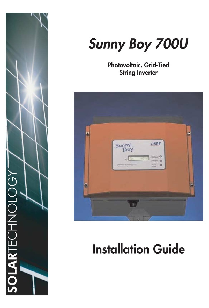
Sunny Boy SWR 850 Parts list manual

Sunny Boy
Technical Description
Edition 4.1
SWR 700 and SWR 850
The String Inverter for Photovoltaic Plants
SWR700-14:EE0698

Sunny Boy Technical Description
SWR700-14:EE - 2 - SMA Regelsysteme GmbH

Sunny Boy Technical Description
Alteration Review
Document-
Number
SWR700
Version
and Alteration
Review1)
Comments Author
-12:EE1296 2.0 A First Edition
-13:EE1497 3.0 C Extension to SWR 850
-13:EE3397 3.1 C Recommendation for fuses
Modification of parameter lists
-14:EE0698 4.0 C
1) A: Alterations due to faulty documents or improvement of the documentation
B: Alterations maintaining full or upward compatibility
C: Alterations limiting or excluding compatibility
Name Date Signature
Release
SWR700-14:EE - 3 - SMA Regelsysteme GmbH

Sunny Boy Technical Description
Explanation of Symbols (used in this Document)
To enable you to make optimal use of this manual and safe use of the device during
commissioning, operation and maintenance, please not the following description of
symbols.
This symbol indicates a fact the non-observation of which may cause a
loss of comfort or an impairment of the function.
Example: “Do the following in order to keep the string voltage free“.
This symbol indicates a fact the non-observation of which may lead to da-
mages of parts or to the endangering of people.
Example: “Disconnect the AC and DC cabling before opening the device“.
This symbol indicates an example.
SWR700-14:EE - 4 - SMA Regelsysteme GmbH

Sunny Boy Technical Description
Content
1 Review......................................................................................................................7
1.1 General Information...........................................................................................7
1.2 Who Should Read Which Chapters?.................................................................7
1.3 What to do in Case of Transportation Damages................................................8
2 System Description...................................................................................................9
2.1 Function of a Mains-Connected Solar PV Plant ................................................9
2.2 Key Component Inverter ...................................................................................9
2.3 The String Inverter SWR 700 and SWR 850 ...................................................11
2.3.1 Design......................................................................................................11
2.3.2 Mains Disconnection Device ....................................................................13
2.3.3 Diagnosis and Communication.................................................................16
3 Installation ..............................................................................................................18
3.1 Placement of the SWR 700 resp. SWR 850....................................................18
3.2 Delivered Mounting and Installation Parts .......................................................20
3.3 Device Installation ...........................................................................................21
3.3.1 General Information .................................................................................21
3.3.2 Mounting Preparations .............................................................................21
3.3.3 Wall Mounting ..........................................................................................22
3.4 Electrical Conntection......................................................................................22
3.4.1 General Information .................................................................................22
3.4.2 Connecting Preparations..........................................................................23
3.4.3 Cable Connection.....................................................................................31
4 Putting into Operation.............................................................................................41
4.1 General Information.........................................................................................41
SWR700-14:EE - 5 - SMA Regelsysteme GmbH

Sunny Boy Technical Description
4.2 Before the First Switching On..........................................................................41
5 Operation and Failure Display ................................................................................43
5.1 Operation Display............................................................................................44
5.2 Failure Display.................................................................................................46
6 Technical Data........................................................................................................52
6.1 SWR 700 .........................................................................................................52
6.2 SWR 850 .........................................................................................................58
7 Sunny Data.............................................................................................................63
7.1 General Information.........................................................................................63
7.2 Data Transmission ..........................................................................................63
7.2.1 Data Transmission via Mains Lead ..........................................................63
7.2.2 Data Transmission via Separate Data Line ..............................................64
7.3 Diagnosis and Communication........................................................................67
7.4 Graphical User Interface using MS Windows ..................................................68
8 Guaranty Regulations and Liability .........................................................................69
9 Enclosures..............................................................................................................72
9.1 Supplement 1: Certificates for SWR 700.........................................................72
9.2 Supplement 2: Certificates for SWR 850.........................................................76
9.3 Supplement 3: Boring jig .................................................................................80
SWR700-14:EE - 6 - SMA Regelsysteme GmbH

Sunny Boy Technical Description
1 Review
1.1 General Information
With the Sunny Boy (SWR 700 resp. SWR 850), you have purchased the technically
most advanced inverter for the mains connection of photovoltaic plants at present. The
SWR 700/850 complies with all VDEW (Vereinigung Deutscher Elektrizitätswerke) regu-
lations -Regulations for the Parallel Operation of Private Generating Plants with the Low
Voltage Grid of the Power Utility. This includes the compliance of the SWR 700/850
with the regulations of the Berufsgenossenschaft der Feinmechanik und Elektrotechnik
regarding the "Automatic Disconnecting Device for Private Generating Plants" (The
certification is included in the supplements). Furthermore, the SWR 700/850
complies with the relevant harmonized European regulations according to the EMVG
(EMI Regulations) and therefore has a CE conformity certificate (v. supplements).
Presently you are reading the Technical Description of the Photovoltaic Inverter SWR
700 resp. SWR 850 (Sunny Boy), and you are probably surprised at its size. Don't
bother, you do not have to read all chapters; this Technical Description shall provide all
necessary information concerning function, installation, and operation of the inverter as
well to the installer as to the user, and it shall give some hints regarding the extension of
solar plants.
1.2 Who Should Read Which Chapters?
Reading this manual is necessary mostly for the installer, because the inverter starts
automatically, without any user action. This Technical Description contains important
information concerning the installation and the putting into operation of the device, besi-
des other topics. In any case, the installer should read at least chapters 3 to 6 of this
description carefully before starting to work, and chapter 8, Guarantee Regulations and
Liability.
SWR700-14:EE - 7 - SMA Regelsysteme GmbH

Sunny Boy Technical Description
The user should read at least chapters 1 and 5. As an aid for fast finding the desired
information, we recommend to read the following chapters.
Installer: Chapter 1, chapter 3, chapter 4, chapter 5, chapter 6,
chapter 8
User: Chapter 1, chapter 2, chapter 5, chapter 7, chapter 8
1.3 What to do in Case of Transportation Damages
Before delivering our products, we thoroughly check their orderly state.
Transportation damages may occur in spite of the good packaging, which, by the way,
can be recycled. In most cases the carrier is responsible for these.
Please examine the delivered string inverter thoroughly. In case you find any packing
damages suggesting inverter damages, or in case you even find damages or deficien-
cies of the inverter itself, please inform the carrier immediately.
If necessary, your distributor or the company SMA will support you. In any case, a notifi-
cation of damages must be submitted to the carrier in writing within six days from the
receipt of the goods.
SWR700-14:EE - 8 - SMA Regelsysteme GmbH

Sunny Boy Technical Description
2 System Description
The reduction of CO2and other power generating emissions polluting the environment
becomes more and more pressing. Regenerative power generation can be an important
contribution to this. Especially the direct conversion of solar radiation to electric power
(Photovoltaic) has an eminent, worldwide importance.
2.1 Function of a Mains-Connected Solar PV Plant
The DC generated in a solar generator is converted by a so-called "Mains Connection
Device" or "Inverter" to mains-conforming AC, and is supplied directly to the household
mains, which in turn is connected to the public power supply grid.
In the house it supplies all connected electricity consumers (household appliances,
lamps, etc.). In case of insufficient solar power supply, additional power is automatically
taken from the public grid to secure the operation of all connected devices. Surplus solar
power not needed in the household is supplied directly to the public grid, and is made
available for other electricity consumers in this way.
2.2 Key Component Inverter
The DC from the solar cells must be converted to mains-synchronous AC, before it is
supplied to the household mains connected with the public grid. The string inverter con-
nects only a small number of solar modules in series to the public grid (this is called a
string). In this way, even quite large solar generators can be composed from many small
strings, each equipped with a string inverter of its own. The interconnection resp. power
collection takes place on AC side. This means that the expensive DC distribution of for-
mer photovoltaic plants can be omitted, and that additional planning is nearly not neces-
sary any more for the installation of such plants.
SWR700-14:EE - 9 - SMA Regelsysteme GmbH

Sunny Boy Technical Description
The string inverter to be installed for this purpose should meet the following re-
quirements:
• High efficiency, especially in the partial load range
• Microprocessor-equipped operation control for automatic working point opti-
mization of the solar generator (Maximum Power Point Tracking)
• Personnel protection (avoidance of dangerous contact voltages) during instal-
lation and operation
• Operation in accordance with the regulations of the power utilities
• Avoidance of reactive power (phase shift between current and voltage) and
harmonic currents
• Fully automatic operation
• Simple installation (One-Man installation, standard terminals, etc.)
• Low investment
• Modularity for later plant enlargement
• User information concerning the most important operating states via integrated
LEDs
• Automatic failure diagnosis and indication via LEDs
• Simple solar generator design, simple cable layout
• Transmission of measured values and operating states via mains lead to a PC
The string inverter SWR 700 resp. SWR 850 ideally meets the above mentioned requi-
rements.
SWR700-14:EE - 10 - SMA Regelsysteme GmbH

Sunny Boy Technical Description
2.3 The String Inverter SWR 700 and SWR 850
The experience from more than 3,000 mains-connected photovoltaic plants in Germany
in the power range from one to some hundreds of kilowatts have shown that the system
installations in PV plants with central inverters come up to 50 % of the plant expenses.
To significantly reduce these system costs - i.e. expenses for cabling on DC side, for the
inverter, and for the distribution on AC side - and to drastically simplify the installation of
photovoltaic plants were the starting points for the development of the string inverter
SWR 700. Later on the SWR 850 followed.
In cooperation with the Institut für Solare Energieversorgungstechnik (ISET) and the
Institut für Elektrische Energietechnik (IEE) of the University Gesamthochschule Kassel,
SMA Regelsysteme GmbH has developed a modular system, the basic unit of which is
the string inverter SWR 700 resp. SWR 850.
The string inverter SWR 700/850 is a consequent improvement, based on the rich ex-
perience of SMA with photovoltaic mains connection devices. To give some numbers,
SMA has built more than 20 MW installed inverter power, which means more than 6000
devices with a power from 1000 W up to 500 kW.
With the string inverter SWR 700/850, a new, significantly simpler and less expensive
system technology for the mains connection of photovoltaic plants will prevail.
2.3.1 Design
A simple, absolutely robust construction with high efficiency and extreme availability
characterizes the power unit. The photovoltaic DC is converted via a MOSFET bridge
circuit in an intermediate AC circuit with high frequency (20 kHz). From there the supply
to the mains is carried out directly via a ring core transformer. The nominal power of the
SWR 700 is dimensioned for the series connection of up to 10 PV modules (36 to 40
cells each). Regarding the PV generator power to be connected, the SWR 700 can be
re-configured so that even low PV generator power can be connected;
SWR700-14:EE - 11 - SMA Regelsysteme GmbH

Sunny Boy Technical Description
the SWR 850 can only be operated in one voltage range. In all cases, the PV modules
are getting wired using the simple series connection.
Fig 2.1: Block diagram of the string inverter SWR 700 resp. SWR 850
The control of the supplied current via a one-chip computer guarantees absolutely sinu-
soidal curve shapes and extremely low distortion. The operation control serves for fully
automatic operation and the MPP-tracking. Unneccessary losses during idle as well as
feeding operation are avoided.
The heat dissipator is so large that the nominal power of the SWR 700 can permanently
be supplied, even in environments with high ambient temperatures (e.g. installation di-
rectly under the roof). In spite of generous dimensioning of the heat dissipator of the
SWR 850 the supervision of the heat dissipator's temperature is integrated that means
the SWR 850 decreases the power in case of inadmissible temperatures.
Besides the pure operation control, there is the possibility to put out data and to receive
commands and data. This makes the Sunny Boy universally applicable: As well as au-
tonomically working single device as in the frame of a large PV plant, the operation of
which is to be be supervised and evaluated from one center.
SWR700-14:EE - 12 - SMA Regelsysteme GmbH

Sunny Boy Technical Description
The mains is getting supervised by two parallely working, independent one-chip micro-
computers; it fully complies with the new supply regulations of the VDEW and the em-
ployers' association (mains impedance measurement, disconnection device). This me-
ans that the Sunny Boy can be connected to the household mains nearly everywhere in
the house. The result is simplest installation.
The SWR 700 has a metal case with the protection type IP65. This high protection type
and the extended temperature range make possible the installation at any place (loft,
outdoors, etc.).
Even for small PV plants, personnel protection is a vital feature: The galvanic separation
of mains and PV generator, and the supervision of insulation are a proven conception
for this. Of course, the German resp. European regulations concerning electro-magnetic
induction (EMI), harmonic distortions, etc. are met so that the device can be used
without problems all over the world.
2.3.2 Mains Disconnection Device
This chapter deals with the safe mains disconnection of inverters in case of a public grid
disconnection on side of the utility. This means that an absolute protection of electricians
and other workers must be guaranteed in case the utility disconnects a part of the public
electric grid, e.g. for maintenance works. For this purpose, a new protection concept
exists, proposed by the employers' associations, which has become part of the VDEW
regulations in 8/94.
The string inverter SWR 700 resp. SWR 850 (Sunny Boy) is only to be used in parallel
operation with the mains. For safe disconnection during mains disconnections etc., and
to avoid isolated operation, the SWR 700 as well as the SWR 850 are equipped with an
automatic disconnection device as standard.
SWR700-14:EE - 13 - SMA Regelsysteme GmbH

Sunny Boy Technical Description
This device is an "Automatic Disconnection Device for Household Generating
Plants with a Nominal Power ≤4.6 kVA with One-Phase Parallel Supply to the
Public Supply Grid via Inverter".
Important is that the automatic disconnection device consists of two independent devi-
ces for mains supervision, each equipped with a disconnector, connected in series for
maximum protection. This device permanently supervises the quality of the connected
grid via checking its voltage, frequency, and impedance. The redundant design and an
automatic self-test before each connection to the mains guarantee its safe function.
Whilst earlier disconnection devices did only check the voltage of the interconnected
three-phase mains, the new conception mainly uses the mains impedance resp. the
mains impedance alterations in the one-wire mains (feeding phase) as a measured va-
lue for disconnection. In addition, voltage and frequency in the one-wire mains are also
checked. If the mains impedance alters by a certain value in a certain time (_ ZAC ≥0.5
Ω), or if it exceeds a maximum value (ZAC ≥1.75 Ω), the inverter will be disconnected
from the mains within 5 s.
Equally, the inverter must not be connected to the mains if a maximum impedance value
is exceeded (ZAC < 1.25 Ω).
In case the mains voltage exceeds or falls short of certain values (-15/+10 % UN), the
disconnection from the mains must take place within 0.2 s.
Frequency deviations above a certain range (± 0.2 Hz at UN-30/+15 %) must equally
cause a mains disconnection within 0.2 s.
The new conception realized in the SWR 700/850 reaches maximum safety. Never-
theless, the installation expenditure for the owner of a solar plant is drastically reduced,
because now a one-phase connection of the inverter suffices.
The basic concept of the mains disconnection device is based on measuring the grid
impedance (internal resistance of the public supply grid) besides voltage and frequency.
SWR700-14:EE - 14 - SMA Regelsysteme GmbH

Sunny Boy Technical Description
The grid impedance is measured by every Sunny Boy just at the place where it is con-
nected to the mains.
The measured grid impedance is composed from the impedance of the public grid and
the mains impedance in the house (from the house connection to the SWR 700/850). A
high grid impedance increase caused by the connection lead to the SWR 700/850 must
therefore be avoided.
We recommend not to exceed an impedance increase of about 0.5 Ωdue to the con-
nection lead between house connection and SWR 700 resp. SWR 850 (further notes
are given in chapter 3.4.3.2, Mains Connection).
The VDEW regulations prescribe a type test, which must be carried out by the inverter
manufacturer at a qualified testing authority. Furthermore, the manufacturer has to
check the function of the mains disconnection device of every unit before delivery. For
the user of a solar plant this means that no time-consuming disconnection test by the
utility and the installer is necessary at the site, and the formerly prescribed repeated
tests are cancelled.
The decisive arguments for the omission of repeated tests are the redundant design and
the recurring self-test of the disconnection device. During every new mains connection
the orderly function of the mains supervision is to be checked, and it is to be guaranteed
that the appertaining switching devices (transistor bridge, relay) are working and able to
disconnect the load circuit. In case of a negative test result, the complete self-test will be
repeated. If the negative result occurs again, the disconnection device has to be che-
cked by a specialist. That's why the operation will be locked in this case, which will be
indicated to the user via lighting the failure LED (yellow) and switching off the operation
LED (green). This operation state will be recorded, and cannot be left via simple swit-
ching operations from the outside (signals via the serial interface, resetting the internal
computers, switching off and on the device, etc.). This makes sure that only authorized
specialists can unlock the device for feeding action after testing the disconnection devi-
ce.
SWR700-14:EE - 15 - SMA Regelsysteme GmbH

Sunny Boy Technical Description
In short the new mains disconnection conception realized in the SWR 700/850 stands
out for the following features:
• Maximum safety
• Simpler and less expensive installation (one-phase)
• No expensive single device test for the user
• No repeated tests needed
2.3.3 Diagnosis and Communication
The conception of modular PV system technology leads to a spatially distributed place-
ment of string inverters SWR 700/850. A simple and fast function check via status and
measured value monitoring of each SWR 700 resp. SWR 850 is offered optionally; it
takes place centrally on a PC using the Windows-program Sunny Data.
The signal transmission between the PC and all inverters takes place via the existing
mains leads (by using a power line modem integrated in the SWR 700/850) so that no
additional signal lines are necessary. The communication supports the following functi-
ons:
• Continuous acquisition of operation data of all connected string inverters and
their PV module groups
• Supervision of operating states and failure indication
• Online measured data transmission from one selectable SWR 700/850
• Identification of faulty strings
• Graphical representation of the data of one SWR 700/850, or comparison of the
data of several ones
SWR700-14:EE - 16 - SMA Regelsysteme GmbH

Sunny Boy Technical Description
Communication and further processing takes place on a PC, which is connected to the
string inverters via a small plug-in modem (can be plugged in any 230 V socket). The
PC can be connected at any place, because it gets its data "from the socket".
The comfortable PC program Sunny Data from SMA offers you a fully graphical user
interface and all features of Windows. In this way Sunny Data makes available the most
comfortable interface you can get today.
SWR700-14:EE - 17 - SMA Regelsysteme GmbH

Sunny Boy Technical Description
3 Installation
The installation of a SWR 700/850 must be carried out by authorized
specialists. The installer must be licensed by the local power utility.
Please read the chapter "Installation" carefully.
All relevant security regulations, the technical connection regulations
of the responsible power utility, and the VDE regulations (resp. compa-
rable regulations) have to be observed.
The SWR 700/850 - Sunny Boy - is a highly integrated electronic device,
therefore sensitive to humidity within its case.
If a SWR 700 is installed outside, the air humidity must not be extreme-
ly high, especially it must not rain into the case during installation, be-
cause the air moisture would remain in the device after closing the ca-
se, which might lead to damages due to condensation on electronic
parts.
3.1 Placement of the SWR 700 resp. SWR 850
When planning a PV solar plant, the question of where to locate the inverter(s) is defini-
tely of some importance. In the following you will find some criteria, which may help you
in this decision.
Basically, the SWR 700/850 is designed for wall mounting on even ground.
SWR700-14:EE - 18 - SMA Regelsysteme GmbH

Sunny Boy Technical Description
Criteria for device mounting:
• Due to the high protection type IP65 the installation is possible as well indoors
as outdoors.
• If possible, do not expose the inverter to direct moisture despite IP65.
• Minimization of the line length (DC cabling) to the solar generator.
• Electric connection to the household mains possible at any place. (Caution! Ta-
ke heed of the mains impedance at the connection point, v. chapter 2.3.2 and
3.4.3.2)
• Avoid the installation in the living area, because low noise emission is possible.
• Avoid the mounting on resonant parts (e.g. thin wooden panels, plaster panels,
etc.).
• Take heed of accessibility for installation works and later servicing.
• Installation in eye-height makes possible to simply read the operating indicators
(LEDs).
Please note the following points in any case:
The mounting ground must be firm.
The ambient temperature must not fall short of resp. exceed -25 oC and
+60 oC.
Do not expose the string inverter to direct sunlight (if necessary install a
shading roof).
A
minimum distance of 200 mm is to be kept to other devices, cupboards,
ceiling, etc.
The free air circulation around the case must not be obstructed.
If installing the SWR 700 resp. SWR 850 in a switch cabinet etc., the ai
r
SWR700-14:EE - 19 - SMA Regelsysteme GmbH

Sunny Boy Technical Description
circulation must be sufficient for heat dissipation.
The heat dissipator can reach a temperature of more than 60oC.
3.2 Delivered Mounting and Installation Parts
In the following you will find a list of components making possible the easy mounting and
installation of a SWR 700/850; they are included in the extent of delivery:
1 Boring jig (for a scheme of the boring jig v. fig. 3.1)
5 Screwings PG 13.5
3 Blind screwings PG 13.5
6 Counter-nuts PG 13.5
Fig. 3.1: Boring jig scheme
SWR700-14:EE - 20 - SMA Regelsysteme GmbH
This manual suits for next models
1
Table of contents
Other Sunny Boy Inverter manuals
Popular Inverter manuals by other brands

APsystems
APsystems QT2 installation manual

Global Sources
Global Sources Stepup-Tech GTB Series quick start guide

Comfortaire
Comfortaire A-VFH30QB-1 Installation & operation manual

CanadianSolar
CanadianSolar CSI-75K-T480GL03-U Installation and operation manual

Tripp Lite
Tripp Lite PowerVerter APSX3024SW Specification sheet

DualLite
DualLite LiteGear LG Series Installation instructions and user manual