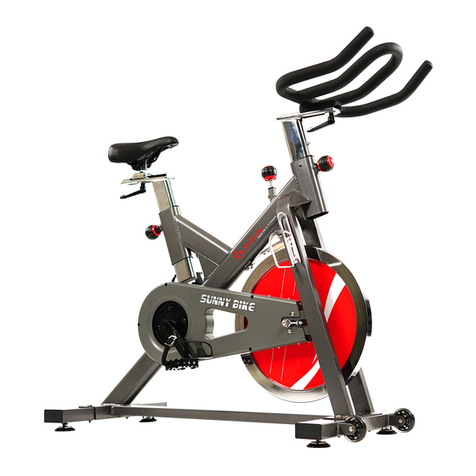
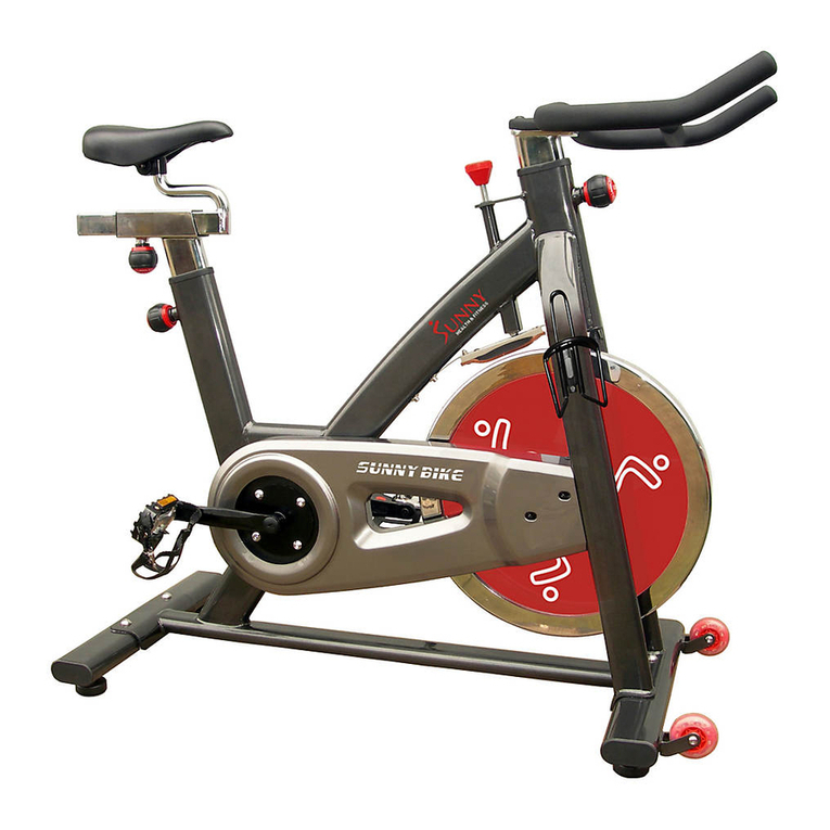
Sunny SF-B901 User manual

SUNNY PRO INDOOR CYCLING BIKE
USER MANUAL
SF-B901
IMPORTANT: Read all instructions carefully before using this product. Retain
owner’s manual for future reference. For customer service, please contact:


CONTENTS
SAFETY GUIDELINES …………………………………………... 3
UNIT GENERAL KNOWLEDGE ………………………………… 4
EXPLODED DRAWING …………………………………………... 5
PARTS LIST ……………………………………………………….. 6
INSTALLATION …………………………………………………… 8
NOTICE …………………………………………………………….. 12
INSTRUCTIONS ON CHANGING BRAKE PAD ……………… 13
2

SAFETY GUIDELINES
1. It is important to read this entire manual before assembling and using the equipment.
2. Once assembled fully, please inspect to make sure all hardware parts such as bolts,
nuts and washers are positioned correctly and tightly secured.
3. Always inspect the safety chain guard that protects the moving parts of the bike to be
in safe and good order.
4. Always inspect the seat post, seat slider, pedals and handlebar to make sure they are
in safe and stable position before using the bike.
5. It is recommended that you lubricate all moving parts on a monthly basis.
6. To avoid entangling into any moving parts, do not wear loose clothing.
7. Do not remove feet from the pedals while they are in motion.
8. Running or aerobic shoes are required when using the bike.
9. Dry the bike after each use to remove sweat and moisture. Wipe your bike regularly
with a mild, non-abrasive cleaner and water solution. To avoid damaging the finish on
the bike, never use a petroleum-based solvent when cleaning.
10. Please keep children away from the bike while it is in use. Do not allow children to use
the bike. This bike is designed for adults, not children.
11. Do not dismount the bike until the pedals are at a complete STOP.
12. Before starting any exercise program, consult with your physician first. He or she can
help establish the exercise frequency, time and intensity appropriate for your particular
age and condition.
13. If you have any pain or tightness in your chest, an irregular heartbeat, shortness of
breath, feel faint or have any discomfort while you exercise, STOP! Contact your
physician before continuing.
14. Do not place fingers or any other objects into moving parts of the exercise equipment.
15. After exercising, please turn the adjustment control knob clockwise (+) to increase
tension so the pedals will not rotate freely and possibly hurt someone while bike is not
in use.
16. This equipment is designed for indoor and home use only, not intended
for .commercial use.
17. The maximum user weight is 275 Lbs, please do not overload.
WARNING: This product can expose you to one or more chemicals known to
the State of California to cause cancer and birth defects or reproductive harm.
For more information go to www.P65Warnings.ca.gov.
3

UNIT GENERAL KNOWLEDGE
Adjust the resistance by turning the adjusting Knob, and brake by pressing the Brake
Handle. The equipment is suitable for using at home, in office, or other small places of
leisure for fitness.
1. Maki sure the equipment is stable before exercise, if the ground isn’t flat, you can
adjust Base Levelers (16) on the bottom of the stabilizers to help equalize the bike’s
position.
2. Adjust Seat (22) to a suitable position by adjusting Seat Slider (3) and Seat Post (2).
Please adjust height of Handlebar (5) according to your body size.
3. Set correct resistance by turning Tension Knob (11), please set the right resistance
according to your body’s conditioning.
4. The drive mode of the equipment is bi-directive drive.
5. Do not get off the bike until all parts come to a complete stop. Please press the Brake
Handle (9) for braking when aggressive exercise is performed, it will stop immediately.
4

EXPLODED DRAWING
5

PARTS LIST
No.
Description
Qty
No.
Description
Qty
1
Main frame
1
33
Flat washer φ20*φ10*1.5
4
2
Seat post φ38*460*t4.5
1
34
Hexagon flat round head screw M10*25
4
3
Seat Slider 38*38*270*t1.5
1
35
Pedal (L/R) 9/16”-20UNF-RH
2
4
Handlebar post φ38*270*t1.5
1
36
Flywheel (18KG)
1
5
Handlebar φ28*998*t1.5
1
37
Flywheel spindle
1
6
Cap nut M12*1.0
2
38
Chain adjuster welding
2
7
Rear base flat oval 40*80*t1.5*l500
1
39
Sleeve φ18*φ12*18.5L
1
8
Front base flat oval 40*80*t1.5*l500
1
40
Nylon nut M8
2
9
Brake-handle
1
41
Brake pad
2
10
Washer φ10*φ25*t4
1
42
Clamp brake holder t4.0*M10*P1.25
1
11
Tension knob M10*60
1
43
Flat washer φ10.2-φ25*T1.5
1
12
Left crank
1
44
6001 (Black plastic rind ) ABEC-5
2
13
Cross self-tapping screw
7
45
6004 (Black plastic rind
) ABEC-5
2
14
Chain cover A
1
46
608
4
15
Chain cover B
1
47
Bi-direction small chain wheel 1-3/8”-
24UNF-RH
1
16
Base leveler M10
4
48
C-shaped buckle φ20
1
17
Post housing suitable for 45*45*1.5
square tube & 38*38 square tube
3
49
Inner hexagon flat round head screw
M10*H7*S17
4
18
Cap of bases suitable for 40*80*t1.5
elliptical tube
4
50
Inner hexagon hollow bolt
φ7.8*30*M6*15*S5
3
19
Cap of seat slider suitable for
38*38*t1.5 square tube
1
51
Nut M6*38*S5
1
20
Front cover for chain drive system
1
52
Flat washer d5*10*1
2
21
Transport wheel d8*d71.5*w223
2
53
Hexagon flange nut M10*P1.25*8
2
22
Seat
1
54
Cross recessed countersunk bolt M5*22
2
23
Pop pin M16*p1.5*35L
3
55
Hexagon thin nut M12*1.0 (Rigidity
16~23HRC)
3
24
End cap φ21
1
56
Hexagon flange nut M6 (Rigidity
16~23)
1
25
Cap of inner pipe 45*45*t2 square
tube
1
57
Locknut 1*3/8-24UNF-RH
2
26
Washer φ6.5*φ25*6
2
58
Nylon nut M10
1
27
Nut t0.8*11
5
59
Cross pan head bolt M5*12 (Rigidity
16~23)
2
28
Silent chain 53 burl 2~P=12.7
1
60
Inner hexagon flat round head screw
M6*12*S5
3
29
Flat washer φ12*1.5
2
61
Pedal strap
2
30
Bottom bracket axle φ20*152
1
62
Pedal belt
2
31
Right crank +big chain wheel 52t
9/16”*20UNF-RH
1 set
63
Brake cable
2
32
Crank cover
2
64
Clamp brake assembly
1
6

65
Brake pad holder 96*35*19
2
68
Front packing base 220*80*40
1
66
Hexagon flat round head screw-
black M10*25
2
69
Rear packing base 220*/0*40
1
67
Flat washer-black φ20*φ10*1.5
2
70
Inner hexagon flat round head screw
1
7

INSTALLATION
According to the Exploded Figure and parts list,take out all parts from carton.
STEP 1: Disassemble Front Packing Base and Rear Packing Base
Take out Main Frame from Carton, remove Inner Hexagon Flat Round Head Screw
M10*16L (70), and take off the Front Packing Base (68), and Rear Packing Base (69)
from the bike.
8

STEP 2: Assemble Front Base and Rear Base
According to the following figure, fix the Front Base (8) and Rear Base (7) to Main
Frame (1) with Flat Washer (33) and Inner Hexagon Flat Round Head Screw (34) using
Inner Hexagon Wrench.
STEP 3: Install Left and Right Pedal
IMPORTANT: Read instructions carefully, failure to do so may cause permanent
damage to your bike.
Before you begin: Turn the resistance knob all the way to the right until the crank arms
are immobilized.
Left Pedal: Please make sure the pedal in your hand is the Left pedal before installation.
Refer to the figure, align the Left Pedal with Left Crank at 90°. Gently insert the pedal
in the crank arm, turn the pedal counter-clockwise as tightly as you can with your hand.
Use the Spanner #15 to ensure it is tightened securely. Please always tighten by hand
first, then finish by Spanner.
Right Pedal: Please make sure the pedal in your hand is the Right pedal before
installation. Refer to the figure, align the Right Pedal with Right Crank at 90°. Gently
insert the pedal in the crank arm, turn the pedal clockwise as tightly as you can with
your hand. Use the Spanner #15 to ensure it is tightened securely. Please always
tighten by hand first, then finish by Spanner.
Note: Please make sure pedals are securely connected when assembling; and also
each time you use the bike. Riding this bike backwards may loosen the pedals which
will damage the threads. Always check pedals to ensure the pedals are tightened.
9

STEP 4: Assemble the Handlebar Post
According to the following figure, loosen and pull the Pop Pin (23), and slide the
Handlebar Post (4), into the Handlebar Post Housing on the Main Frame (1), and re-
tighten the Pop Pin.
STEP 5: Assemble the Handlebar
Fix the Handlebar (5) to the Handlebar Post (4) and tighten it with Hexagon Flat Round
Head Screw-black M10*25L (66) and Flat Washer-black (67).
10

STEP 6: Assemble the Seat Post
Loosen and pull the Pop Pin (23), and slide the Seat Post (2) into the Seat Post
Housing on the Main Frame (1), then retighten the Pop Pin (23).
STEP 7: Assemble the Seat
Loosen and pull the Pop Pin (23) and slide the Seat Slider (3) into the Seat Post (2),
then retighten the Pop Pin (23) and fix the Seat (22) to the Seat Slider (3).
STEP 8: Installation Completed
After finishing installation, please inspect all the screws and nuts carefully to make sure
all of them are tightened.
11

NOTICE
Ensure all the Nuts, Nut Caps and Pedals are in a safe situation regularly and inspect
the equipment periodically. If you should find any defective parts, don’t exercise until
they’ve been repaired.
1. Pay more attention to easily damage parts due to wear. Please inspect the Brake
Pads (41) if they fall off, or are not working before exercise. If necessary, please replace
them.
2. Please inspect the pedals before exercise. If they have become loose, please re-
tighten.
3. Please adjust the Hexagon Nut by using the Opening Spanner if the Seat (22) is
loose.
4. If you need to move the bike, please grasp the Handlebar (5) at the very ends to
make the Transport Wheel (21) of Front Stabilizer stand on floor, then the bike can be
moved easily by rolling.
12

INSTRUCTIONS ON CHANGING BRAKE PAD
Step 1: Remove Nylon Nut (58) which is under Brake Knob (11) with Opening Spanner .
φ17 mm first, and then adjust the Brake Resistance to least amount of resistance.
Step 2: Push Left Brake Pad (65) separated from its Holder (64) by hand.
Step 3: Take down the Left Brake Pad (65).
Step 4: Push Right Brake Pad (65) separated from its Holder (64) by Hand.
Step 5: Take down the Right Brake Pad (65).
13

Step 6: Insert the new Right Brake Pad (65) into the Right Holder (64).
Step 7: Open the Left Holder (64) with hand.
Step 8: Insert the new Left Brake Pad into the Left Holder (64).
Step 9: After tightening up the Tension Knob (11), put the Nylon Nut (58) onto and fix it
with Opening Spanner . φ17 mm to the normal working place.
Step 10: Put down the Brake Handle (9) by Left hand; and tap the Brake pad inside its
Holder with wooden mallet (or plastic mallet) gently by right hand..
-END-
14
VVVersion 1.5
Other manuals for SF-B901
3
Table of contents
Other Sunny Exercise Bike manuals

Sunny
Sunny SF-B901B User manual

Sunny
Sunny SF-RB4417 User manual

Sunny
Sunny SF-B1712 User manual

Sunny
Sunny SF-B1110S User manual

Sunny
Sunny SF-B1421 User manual

Sunny
Sunny sf-b1203 User manual

Sunny
Sunny SF-RB1117 Manual

Sunny
Sunny PREMIUM SF-B1852 User manual

Sunny
Sunny P8200 User manual

Sunny
Sunny SF-B2620 User manual

Sunny
Sunny SF-RB4953 User manual

Sunny
Sunny p8100 User manual

Sunny
Sunny ESSENTIAL INTERACTIVE Series User manual

Sunny
Sunny SF-B0638 User manual

Sunny
Sunny SF-B901 User manual

Sunny
Sunny SF-RBD4703 User manual

Sunny
Sunny SF-B901B User manual

Sunny
Sunny SF-RB4616 User manual

Sunny
Sunny SF-BH620062 User manual

Sunny
Sunny MINI CYCLE User manual