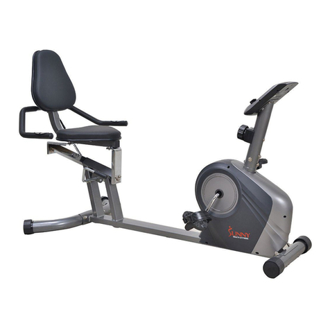
Sunny SF-B2620 User manual

DUAL ACTION RIDER BIKE
SF-B2620
USER MANUAL
IMPORTANT :
Read all instructions carefully before using this product. Retain this manual for

1
PRECAUTIONS
IMPORTANT! Before exercising, please read this manual first and always remember these
safety warnings.
1.
Before starting any exercise program, you should consult your physician to determine if you
have any medical or physical conditions that could put your health and safety at risk or prevent
you from using the equipment properly. Your physician’s advice is essential if you are taking any
medication that may affect your heart rate, blood pressure, or cholesterol level.
2.
Be aware of your body’s signals. Incorrect or excessive exercise can damage your health.
Stop exercising if you experience any of the following symptoms: pain, tightness in your chest,
irregular heartbeat, shortness of breath, lightheadedness, dizziness, or feelings of nausea. If you
experience any of these conditions, you should consult your physician before continuing with your
exercise program.
3.
Keep children and animals away from the equipment.
The equipment is designed for adult
use only.
4.
This equipment is not suitable for therapeutic use.
5.
Always use the equipment as indicated. If you find any defective components while
assembling or checking the equipment, or if you hear any unusual noises coming from the
equipment during exercise, stop using the equipment immediately and don’t use the equipment
until the problem has been rectified.
6.
Batteries can be extremely dangerous if swallowed. Keep batteries away from the reach of
children. If a battery has been swallowed, seek medical help immediately.
7.
Keep packaging material away from children or pets. There is a danger of suffocation.
8.
Do not use the product if it is damaged or defective.
9.
Make sure that no more than one person is using the product at the same time.
10.
Use the product only on a flat level and non-slipping surface. Never use it near water and
keep at least 4 feet of space around it clear when in use.
11.
Take care when lifting and moving the equipment.
Always use proper lifting technique and
seek assistance if necessary.
12.
Protect the product against splashes, humidity, high temperature and direct sunlight.
13.
The high speed rotating pedal may cause damage Do not take your feet out of the pedals or
dismount the bike until the pedals rotating.
14.
When adjusting the seat height, do not exceed the "Max" line. Make sure that the knob is
tightened.
15.
The maximum user weight is 240 lbs.
2
EXPLODED VIEW

3
PARTS LIST
NO.
DESCRIPTION
Q'TY
NO.
DESCRIPTION
Q'TY
A
BOLT M8x45
2
25
PLASTICS COVER (LEFT)
1
B
WASHER Φ8.5*Φ22.0*T1.5
6
26
PLASTICS COVER (RIGHT)
1
C
NUT M8
2
27
END CAP
2
D
WRENCH S13-14-15
1
28
LID
2
E
BOLT M8x45
3
29
RUBBER BLOCK
2
F
SPRING WASHER Φ8.4*Φ13.5*T2.5
3
30
CUSHION
1
G
NUT M8
4
31
END CAP
4
H
KNOB
1
32
CRANK (LEFT)
1
I
PIN Φ8*90
1
33
CRANK (RIGHT)
1
J
WRENCH S6
1
34
MAGNET
6
K
ARC WASHER Φ8.4*Φ19.0*T1.5
2
35
SEAT POST BUSHING
1
L
PIN Φ8*36
1
36
END CAP
2
1
MAGNET SET
1
37
BUSHING
2
2
DRIVING WHEEL
1
38
END CAP
2
3
CONNECTING FRAME
1
39
LINE PLUG
3
4
SLIDING TUBE
1
40
BELT 230PJ3
1
5
MAIN FRAME
1
41
BELT 235PJ3
1
6
HANDLE BAR SUPPORTING POST
1
42
WHEEL
2
7
REAR STABILIZER
1
43
RUBBER CUSHION
1
8
HANDLE BAR
1
44
SENSOR BASE
1
9
SEAT POST
1
45
SENSOR
1
10
FRONT STABILIZER
1
46
COMPUTER
1
11
FOAM GRIP
1
47
WASHER Φ8.5*Φ16.0*T1.5
3
12
WHEEL
2
48
TENSION KNOB AND CABLE
1
13
AXLE
1
49
SPRING WASHER Φ8.0xΦ7.4xT0.8
2
14
SPRING
1
50
SPRING WASHER Φ8.4*Φ13.5*T2.5
1
15
PU WHEELAXLE
2
51
PULLEY(6200)
1
16
SLEEVE
1
52
PEDAL(LEFT)
1
17
CONNECTING AXLE
1
53
PEDAL(RIGHT)
1
18
BUSHING
6
54
CYLINDER
1
19
CONNECTING AXLE
1
55
FOAM GRIP
2
20
MAGNET BASE AXLE
1
56
HANDLE BAR
1
21
BIG WASHER
2
57
SADDLE
1
22
MAGNET BASE
1
58
BOLT M8x45
2
23
COVER(LEFT)
1
59
SPRING WASHER Φ10.2*Φ16.6*T3.0
2
24
COVER (RIGHT)
1
60
BOLT M6x30
1

4
NO.
DESCRIPTION
Q'TY
61
NUT M6
3
62
NUT M8
3
63
NUT M10
1
64
NUT M10x1.25
2
65
SCREW ST4.2x13.0
8
66
SCREW M4x12
5
67
BOLT M6x45
2
68
WASHER Φ10.5*Φ22.0*T1.4
3
69
BOLT M8x20
2
70
BOLT M8x30
2
71
BOLT M8x35
2
72
WASHER Φ8.0*Φ25.0*T2.0
2
73
SPRING WASHER Φ10.0xΦ9.3xT1.0
1
74
BOLT M8x60
1
75
BOLT M10x20
2
76
WASHER Φ6.5*Φ16.0*T1.0
2
77
BOLT M6x12
9
78
BOLT M6x15
2
79
BOLT M6x20
2
80
SCREW ST4.2x15.0
2
81
ARC WASHER Φ8.4*Φ19.0*T1.5
2

5
ASSEMBLY
NO.
DESCRIPTION
Q'TY
5
MAIN FRAME
1
6
HANDLE BAR SUPPORTING
POST
1
7
REAR STABILIZER
1
8
HANDLE BAR
1
9
SEAT POST
1
10
FRONT STABILIZER
1
46
COMPUTER
1
52
PEDAL(LEFT)
1
53
PEDAL(RIGHT)
1
57
SADDLE
1
·Read this manual before
assembly.
·Check the parts first.
·Check the hardware.
·Ensure that you have the right
tools.
·Prepare an area to assemble.
·Follow the instructions carefully.
·Never force the joints.
·Periodically tighten the joints.
·Keep this manual for future
reference.

6
HARDWARE PACKAGE
We strongly recommend you that keep at least 4 feet of free space around the
machine during your workout.
#K Φ8.4
22

7
ASSEMBLY
STEP 1
Attach the Front Stabilizer (#10) to Main Frame (#3) using 2 Bolts (#A), 2 Nuts (#C), 2
Spring Washers(#F)and Washer (#B). Tighten with Wrench (#D).
STEP 2
Attach the Rear Stabilizer (#7) to the Sliding Tube (#4), using 1 Bolt (#E), 1 Washer
(#B), 1 Spring Washer (#F), and 1 Nut (#G). Tighten with Wrench (#D) and Wrench (#J).
Lift the the assembled Rear Stabilizer (#7) up and align the hole on the Rear Stabilizer
(#7) with the hole on the Sliding Tube (#4), then insert the Pin (#L) to secure.
22
22

8
STEP 3
Use left hand to hold the Handle Bar Supporting Post (#6) and the right hand to grasp
the Plastics Cover (#25&26), pull the main frame out horizontally.
STEP 4
Unscrew Washers (#B) and Nuts (#G) from the Saddle (#57).
Attach the Saddle (#57) to the Seat Post (#9) using 3 Washers (#B), 3 Nuts (#G).
Tighten with Wrench (#D).
Then insert Seat Post (#9) into the Main Frame (#5). Insert Knob (#H) and tighten.
22

9
STEP 5
Insert the Pin (#I) to the Handle Bar Supporting Post (#6).
Attach the Handle Bar (#8) to the Handle Bar Supporting Post (#6) using 2 Bolts (#E), 2
Spring Washers (#F), and 2 Arc Washers (#K). Tighten with Wrench (#J).
Insert the Computer (#46) onto the computer bracket on Handle Bar (#8). Connect the
Computer Wire (#46) to the Sensor Wire (#45).
Find the Pedals (52& 53) with marking L, R.
Align the Left Pedal (#52) at 90° angle to Left Crank. Gently insert the pedal onto the
crank arm, making sure it is straight and turn counterclockwise as tightly as you can with
your hand. Use Wrench (#D) to ensure it is tightened securely.
Align the Right Pedal (#53) at 90° angle to Right Crank. Gently insert the pedal onto the
crank arm, making sure it is straight and turn clockwise as tightly as you can with your
hand. Use Wrench (#D) to ensure it is tightened securely.
Assembly is now complete! Before using the bike, check that all parts are tightened and
fastened.
Warning: Do not reverse pedal on this bike. Reverse pedaling will damage the bike.
46
45
45
#K Φ8.4

10
Adjustment Guide
How to adjust the seat height using Knob (H):
A. Turn the knob about 3
times counterclockwise.
B. Using one hand, pull out
the knob, using the other
hand, move the seat post to
the desired height.
C. Insert the knob and turn it
clockwise to tighten.
TENSION ADJUSTMENT
To adjust the tension, turn the
Tension Knob (#48):
Clockwise (+) to increase tension
Counterclockwise (-) to decrease
tension
Note: The Knob (H) must be tightened
to prevent any accident.
CAUTION:
•Do not adjust the height of the seat post
over the MAX line shown on the seat post.
•Do not reverse pedal on the bike. Reverse
pedaling will damage the bike.

11
FOLD UP THE MACHINE
1. Loosen and pull out Knob (#H), then
adjust Seat Post (#9) to the lowest
setting. Pull out the Pin (#I).
3. Hold the Rear Stabilizer (#7) by the
right hand, pull Pin (#L) out first, then
rotate the Rear Stabilizer (#7) as shown
below.
2. Hold the Handle Bar Supporting
Post (#6) by the left hand, and grasp
the Saddle (#57) by the right hand and
push it forward until the oval-shaped
holes on the Handle Bar Supporting
Post (#6) and Main Frame (#5) align
with each other. (Refer to the drawing
No. A).Then insert Pin (#I). (Refer to
drawing No. B).
4. Align the two holes on the Rear
Stabilizer (#7) and Sliding Tube (#4).
Insert Pin (#L) to finish this process.
4
57

12
UNFOLD THE MACHINE
1. Pull Pin (#L) out, hold the the Rear
Stabilizer (#7) by the right hand and
rotate the Rear Stabilizer (#7) as the
following arrow shows. Align the two
holes on the Rear Stabilizer (#7) and
Sliding Tube (#4), then reinsert the Pin
(#L).
3. Hold the Handle Bar Supporting Post
(#6) by the left hand, grasp the Saddle
(#57), then press it downward till the Rear
Stabilizer (#7) touches the ground.
2. Pull out the Pin (#I).
4. Insert the Pin (#I) into the Handle
Bar Supporting Post (#6).
6

13
HOW TO MOVE THE BIKE
Before attempting to move the bike,
please make sure that it has been
properly folded. The Pins (I&L) must
be inserted.
Put your hands on the Handle Bar
(#8), tilt the bike until the Wheels
(#42) are able to move on the ground.
Now you can move the bike to the
desired location with ease.

14
HOW TO USE THE BIKE:
The Dual Function Rider Bike lets you work out both upper and lower body. You have
several workout options:
Biking function
Hold the handlebar and pedal, Rider functi
Biking function
Hold the handlebar and pedal, just like a
regular exercise bike.
Rider function
Put your feet in the pedals, but do not
pedal. Pull on the handlebars.
Two in one function
Pull on the handlebars and pedal at the same time, to work out upper and lower body.

15
OPERATING INSTRUCTIONS
The meter turns on when you start pedaling or when you press a key.
After 4 minutes of inactivity, the meter shuts off.
MODE: Press this button to select and set to a function, hold for 3~4 seconds to reset
TIME, DISTANCE, CALORIES, except ODO, the data will be cleared.
SET: After selecting the function, press this button to set the value of TIME, DISTANCE
and CALORIES. The value of the function will be set on a countdown.
RESET:Press this button for 3 seconds to reset the value of TIME, DISTANCE, or
CALORIES to zero.
FUNCTIONS:
DISTANCE: It shows how many Miles you ran on the machine. It starts from 0.00 to
999.9 MI.
CALORIES: It shows how many calories you burned. It starts from 0.00 to 9999 kcal.
SPEED: It shows the speed of your workout. It starts from 0.00 to 99.9 mi/h.
ODO: It shows the total distance after installing the batteries. (When you replace the
batteries, all the values will reset to ZERO automatically.)
TIME: It indicates how long you exercised. It starts from 00:00 to 99:59min.
RPM: It shows how many revolutions per minute.
SCAN: It shows each function for 4 seconds in the following sequence:
TIME—SPEED—DIST—CAL—ODOL—RPM
COUNTDOWN
You can preset the time, distance or calories or your workout. Press MODE to select the
function. Press SET to increase the value. The meter will count down when you start
pedaling.
If you have problems with the meter display, change the batteries. This meter uses 2
AAA batteries. If you replace the batteries, replace both at the same time. Replacing the
batteries will reset all the values in the meter.

16
Table of contents
Other Sunny Exercise Bike manuals

Sunny
Sunny SF-RB4602 User manual

Sunny
Sunny SF-B1735 User manual

Sunny
Sunny SF-B1401 User manual

Sunny
Sunny SF-B1877 User manual

Sunny
Sunny SF-RB921 User manual

Sunny
Sunny X-BIKE PRO User manual

Sunny
Sunny SF-B1735 User manual

Sunny
Sunny SF-B1714 User manual

Sunny
Sunny SF-B1509 User manual

Sunny
Sunny SF-B1002C User manual

Sunny
Sunny SF-E3865 User manual

Sunny
Sunny SF-B1110S User manual

Sunny
Sunny SF-B1002 User manual

Sunny
Sunny SF-RW5940 User manual

Sunny
Sunny SF-RB420031 User manual

Sunny
Sunny SYNERGY PRO SF-B1851 User manual

Sunny
Sunny SF-B2710 User manual

Sunny
Sunny P8400 User manual

Sunny
Sunny SF-RB4631 User manual

Sunny
Sunny SF-RBE4886 SMART User manual