Sunnydaze Decor BAO-118 User manual

Purchase Date: / / Order/Customer Reference Number:
Thank you for choosing Sunnydaze Decor. We stand behind our brand and the quality of the items we sell.
Replacement parts or products will be sent at our discretion within the 1-year warranty period. Proof of purchase, with
the date of purchase as well as photos of the merchandise defect, must be provided. Photos are used to determine
the cause of defects and for future quality control. Register your warranty at https://tiny.cc/SunnydazeWarranty
If you have any questions, comments or concerns, feel free to contact us by phone at 888-881-4668, by email:
PROPANE FORCED AIR HEATER
40,000 BTU
BAO-118
06/2020BGA1601-40K
READ INSTRUCTIONS CAREFULLY:
Read and follow all instructions. Place instructions in a safe place for future reference. Do not allow anyone
who has not read these instructions to assemble, light, adjust or operate the heater.
D
E
S
I
G
N
C
E
R
T
I
F
I
E
D
WARNING:
—
Do not store or use gasoline or other ammable vapors and liquids in the vicinity of this or any other appliance.
— Service must be performed by a qualied service agency.
This is an unvented portable heater. It uses air (oxygen) from the area in which it is used. Adequate combustion
and ventilation air must be provided. Refer to page 3.
Forced Air means that a blower or fan pushes the air through the heater. Proper combustion depends upon this
air ow; therefore, the heater must not be revised, modied or operated with parts removed or missing. Likewise,
safety systems must not be circumvented or modied in order to operate the heater.
ANSI Z83.7-2011 / CSA 2.14-2011
Page 1 / 11

06/2020
IMPORTANT: Read and understand this manual before assembling, starting or
BGA1601-40K
GENERAL HAZARD WARNING:
Table of Contents
Safety ...................................................................................................................................3-4
Unpacking................................................................................................................................ 4
Product Identication ............................................................................................................... 4
Theory of Operation................................................................................................................. 4
Propane Supply ....................................................................................................................... 5
Installation................................................................................................................................ 5
Ventilation ................................................................................................................................ 6
Operation.............................................................................................................................. 6-7
Maintenance ............................................................................................................................ 7
Storage .................................................................................................................................... 7
Service Procedures ..............................................................................................................8-9
Troubleshooting ..................................................................................................................... 10
Specications ........................................................................................................................ 10
Heater Diagram and Part List .................................................................................................11
Page 2 / 11
WARNING!

06/2020BGA1601-40K
SAFETY
WARNING:Fire, burn, inhalation
combustibles, such as building materials,
from the heater as recommended by the
The heater is designed for use as a construction heater
in accordance with ANSI Z83.7•CGA2.14. (Check with
your local re safety authority if you have questions
about heater use.) Other standards govern the use
of fuel gases and heating products for specic uses.
Your local authority can advise you about these. The
primary purpose of construction heaters is to provide
temporary heating of buildings under construction,
alteration or repair. Properly used, the heater provides
safe, economical heating. Products of combustion are
vented into the area being heated.
We cannot foresee every use which may be made
of this heater.
Propane gas is odorless. An odor-
making agent is added to propane gas. The odor
helps you detect a propane gas leak. However, the
odor added to propane gas can fade. Propane gas
may be present even though no odor exists.
Early signs of
carbon monoxide poisoning resemble the u with
headache, dizziness and/or nausea. If you have
these signs, the heater may not be working properly.
Get fresh air at once! Check for proper ventilation and
have the heater serviced.
1. Install and use the heater with care. Follow all local
ordinances and codes. In the absence of local
ordinances and codes, refer to the Standard for
Storage and Handling of Liqueed Petroleum Gas,
ANSI/NFPA 58 and the Propane Gas Installation
Code, CAN/CGA B149.2. This instructs on the safe
storage and handling of propane gases.
2. Use only the electrical voltage and frequency specied
on the model plate. The electrical connections and
grounding of the heater shall follow the National
Electric Code, ANSI/NFPA 70 or Canadian Electrical
Code, Part 1
3. Electrical grounding instructions - This appliance is
equipped with a three-prong (grounding) plug for
your protection against shock hazards and should
be plugged directly into a properly grounded three-
prong receptacle or extension cord.
4. Use only a three-prong, grounded extension cord.
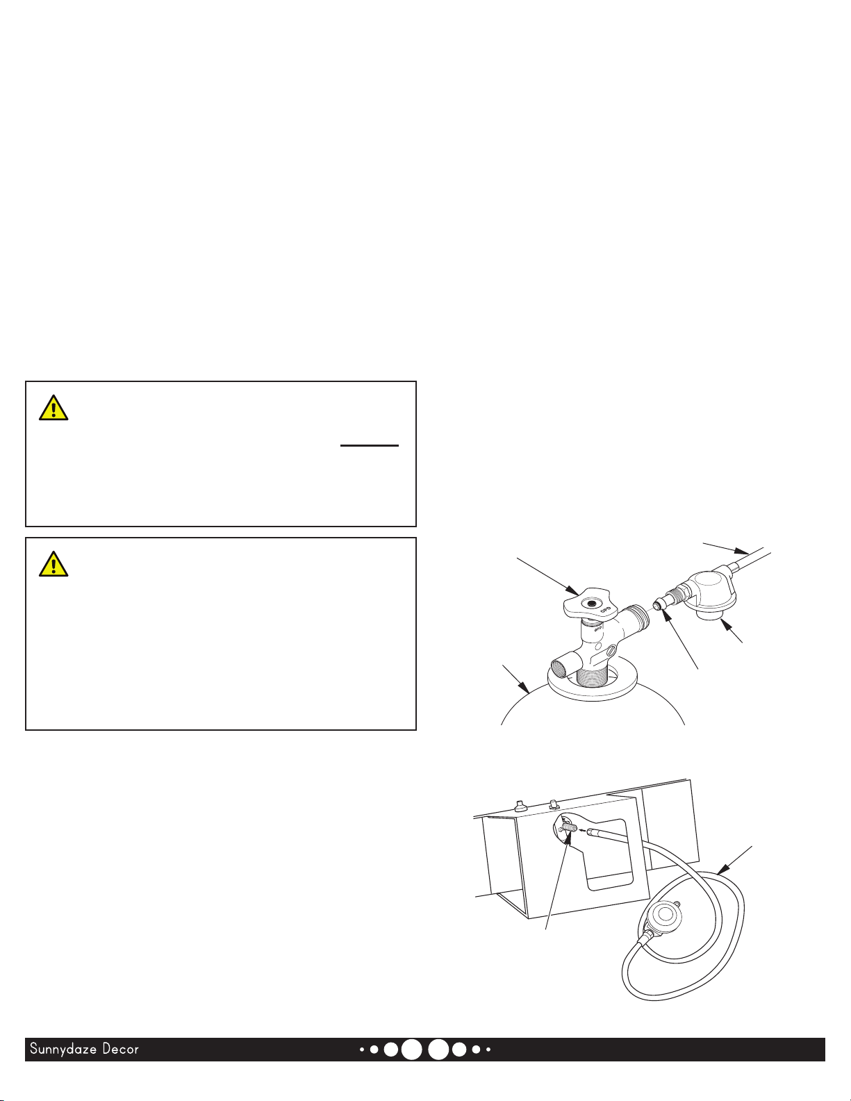
5. Use only the hose and factory preset regulator
provided with the heater.
6. Use only propane gas set up for vapor withdrawal.
7. Provide adequate ventilation. Before using the
heater, provide at least a three square foot opening
of fresh, outside air for each 100,000 BTU (105,500
KJ/Hr) of rating.
8. For indoor use only. Do not use heater outdoors.
9. Do not use the heater in a basement or below ground
level. Propane gas is heavier than air. If a leak occurs,
propane gas will sink to the lowest possible level.
10. Keep the appliance area clear and free from
combustible materials, gasoline, paint thinner and
other ammable vapors and liquids.
11. Do not use the heater in areas with high dust
content. Dust is combustible.
12. Minimum heater clearances from combustibles:
Outlet: 8 ft. (2.4 m), Sides: 2 ft. (0.61 m), Top: 6 ft.
(1.83 m), Rear: 2 ft. (0.61 m).
13. The heater must be located at least 7 ft. (2.13 m) in
the USA or 10 ft. (3 m) in Canada from any propane
gas container. And the heater shall not be directed
toward propane gas containers.
14. Not intended for use on nished oors.
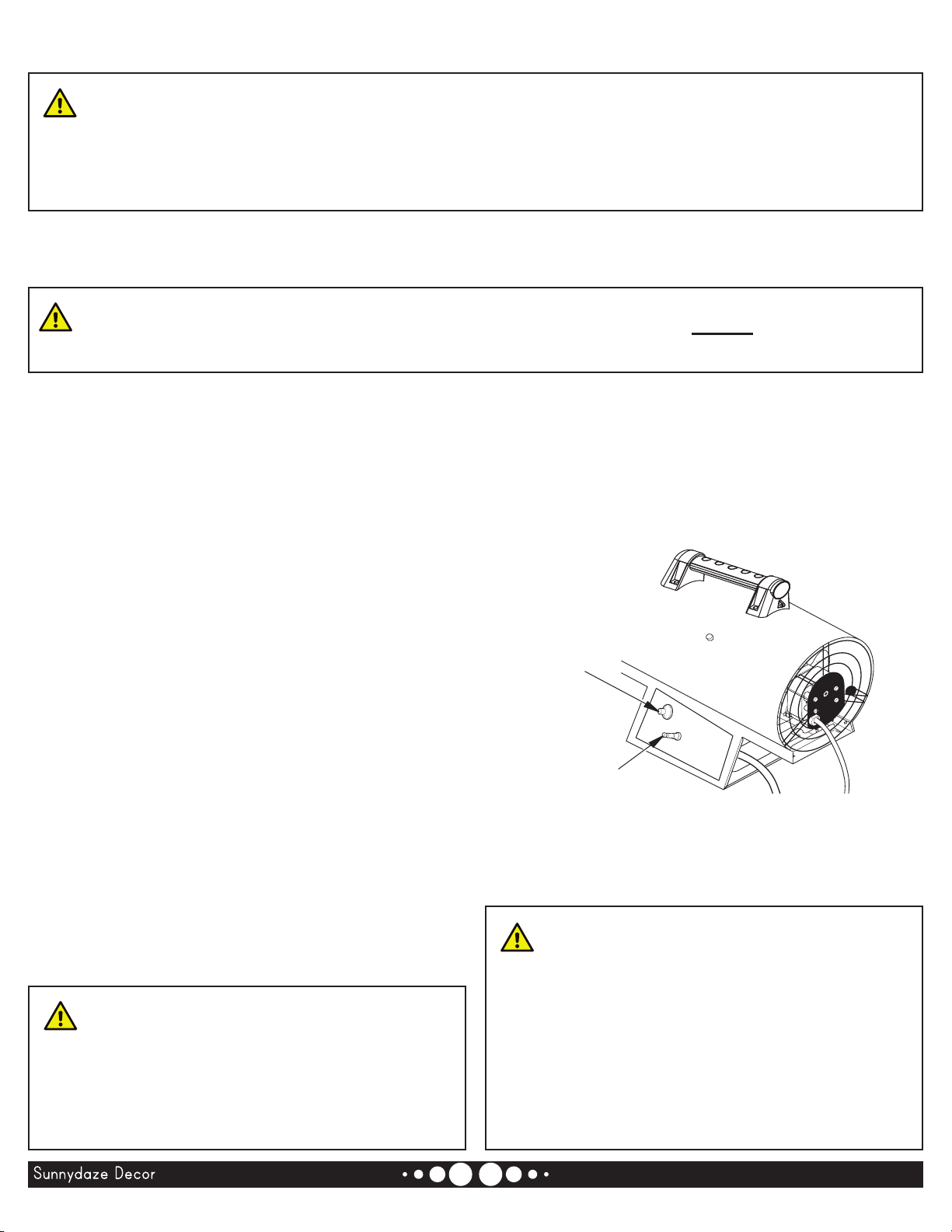
15. Never block the air inlet (rear) or the air outlet (front)
on the heater.
16. Keep heater away from strong drafts, water spray,
rain or dripping water.
17. Do not leave the heater unattended.
IMPORTANT SAFETY INFORMATION
Page 3 / 11
WARNING:

18. Keep children and animals away from the heater.
19. Check the hose before each use of the heater. If
highly worn or cut, replace with a hose specied by
manufacturer before using heater.
20. Locate the heater on stable and level surface if
heater is hot or operating.
21. To prevent injury, wear gloves when handling heater.
22. Never attach duct work to the heater.
23. Do not alter the heater. Keep the heater in its
original state.
24. Never move, handle or service a hot, operating or
plugged-in heater. Severe burns may result. You
must wait 15 minutes after turning the heater o.
06/2020BGA1601-40K
Hot Air Outlet
(Front) Outer Shell
Motor
Power
Cord
Igniter
Button
Automatic
Control Valve
Button
Hose/Regulator
Assembly
Handle
Figure 1 - 35,000 BTU Model Shown
THEORY OF OPERATION
The hose/regulator assembly
attaches to the propane gas supply.
The motor turns the fan. The fan
pushes air into and around the combustion chamber.
This air is heated and provides a stream of hot air.
Figure 2 - Cross Section Operational View
Air For Combustion Air For Heating
Clean Heated
Air Out (Front)
Fan Motor
Cool
Air In
(Back)
Combustion
Chamber
Hose/Regulator
Assembly
The Piezo igniter lights the
burner.
This system causes
the heater to shut down if the ame goes out.
1. Remove all items from the carton.
2. Remove all packing items applied to the heater for
shipment. Keep plastic cover caps (attached to inlet
connector and hose/regulator assembly) for storage.
3. Check all items for shipping damage. If the heater is
damaged, contact customer service via one of the
methods mentioned at the top of page 1.
UNPACKING
PRODUCT
IDENTIFICATION
Page 4 / 11
SAFETY
Continued

PROPANE SUPPLY
This heater is designed to operate with a minimum
20 lb (9 kg) propane tank. Two or more tanks or one
larger tank may be needed in colder weather. A 100
lb (45 kg) tank is recommended for longer operation.
See chart below. Less gas is vaporized at lower
temperatures. Your local propane gas dealer will help
you select the proper supply system. The minimum
surrounding air temperature rating for each heater is
0° F (-18° C).
06/2020BGA1601-40K
At Tank Location
100 lb (45 kg)
Above 0°F (-18°C) 1
Below 0°F (-18°C) 2
Propane gas and propane tank(s) are to be furnished
by the user.
Use this heater only with a propane vapor withdrawal
supply system. The installer must conform with local
codes or, in absence of local codes, with the Standard
for the Storage and Handling of Liqueed Petroleum
Gases, ANSI/NFPA 58 and Propane Gas Installation
Code, CAN/CGA B149.1.
The amount of propane gas ready for use from
propane tanks varies. Two factors decide this amount:
1. The amount of propane gas in the tank(s)
2. The temperature of the tank(s)
INSTALLATION
WARNING: Review and
understand the warnings in the Safety
WARNING: Test all gas
1. Provide propane supply system (
see Propane Supply,
page 5
).
2. Connect QCC tting on hose/regulator assembly to
propane tank(s). Turn QCC tting counterclockwise
into threads on the tank. Tighten rmly using a
wrench. Position regulator so that
hose leaving the regulator is in a horizontal position
(see Figure 3).
3. Connect the hose to inlet connector (see Figure 4).
Tighten rmly using a wrench. Use
extra hose or piping if needed. Install extra hose
or piping between hose/regulator assembly and
propane tank. The regulator supplied with heater
must be used.
4. Open propane supply valve on propane tank(s)
slowly. If not opened slowly, the excess-ow
check valve on propane tank will stop gas ow.
You may hear a click from the excess-ow check
valve closing. If this happens, reset the excess-ow
check valve by closing the propane supply valve
and opening it again slowly.
Figure 3 - Regulator Position
Propane
Tank
Propane
Supply
Valve
Regulator
Hose
QCC
Fitting
Figure 4 - Hose and Inlet Connector
Hose
Inlet Connector
Page 5 / 11

06/2020BGA1601-40K
VENTILATION
WARNING:
heaterProvide at least2(1400 cm2fresh, outside air while running
the heater fresh, outside air ventilation is not , carbon monoxide
OPERATION
TO START HEATER
1. Read and carefully follow all installation, ventilation
and safety information.
2. Place heater on a stable and level surface. Make
sure the front or rear of heater are not exposed to
strong drafts.
3. Plug the power cord of heater into a three-prong,
grounded extension cord. Extension cord must be
at least 6 ft. (2 m) long and must be UL listed.
Up to 50 ft (15 m) long, use 18 AWG rated cord.
51 to 100 ft (16 to 30 m) long, use 16 AWG
rated cord.
101 to 200 ft (30.78 to 60.96 m) long, use 14 AWG
rated cord.
4. Plug extension cord into a 120 volt/60 hertz, 3-hole,
grounded outlet. The motor will start. The fan will
turn, forcing air out the front of the heater.
5. Open propane supply valve on propane tank(s)
slowly. If not opened slowly, the excess-ow
check valve on propane tank will stop gas ow.
You may hear a click from the excess-ow check
valve closing. If this happens, reset the excess-ow
check valve by closing the propane supply valve
and opening it again slowly.
WARNING:
Be sure the motor
WARNING:
Review and understand the warnings in the Safety
6. Push in and hold the automatic control valve button
(see Figure 5). Push Piezo igniter button (see Figure
5). Keep pushing the igniter button until burner
lights. When burner lights, keep the automatic
control valve button pushed in. Release button after
30 seconds. This activates the automatic control
system.
Piezo
Igniter
Automatic Control
Valve Button
Figure 5 - Automatic Control Valve
Button and Piezo Ignitor
WARNING: If the heater is
while the heater is running, the thermal
seconds occur before the thermal limit
Page 6 / 11

06/2020 Page 7 / 11BGA1601-40K
TO RESTART HEATER
1. Wait ve minutes after stopping heater.
2. Repeat steps under To Start Heater, page 6.
3. Store in dry, clean and safe place. Do not store
hose/regulator assembly inside heater combustion
chamber.
4. When taking heater out of storage, always check
inside of heater. Insects and small animals may
place foreign objects in heater. Remove motor and
other internal parts if needed to remove foreign
objects (see Service Procedures, page 8).
OPERATION
Continued
TO STOP HEATER
1. Tightly close the propane supply valve on the
propane tank(s).
2. Wait a few seconds. The heater will burn gas
remaining in the supply hose.
3. Unplug the heater power supply cord.
MAINTENANCE
WARNINGS
•
•
combustible materials, gasoline and
1. Keep the heater clean. Clean heater annually or as
needed to remove dust and debris. If the heater is
dirty or dusty, clean heater with a damp cloth, use
household cleaners on dicult spots.
2. Inspect heater before each use. Check connections
for leaks. Apply mixture of liquid soap and water to
connections. Bubbles forming show a leak. Correct
all leaks at once.
3. Keep inside of heater free from combustible and
foreign objects. Remove motor and other internal
parts if needed to clean inside of the heater (see
Service Procedures, page 8).
4. Clean the fan blades each season or as needed
(see Fan, page 9).
STORAGE
CAUTION:
1. Store propane tank(s) in safe manner. When the
heater is stored indoors, the connection between
the propane supply cylinder and the heater must
be disconnected.
2. Store propane cylinder(s) in accordance with local
laws and regulations. In the absence of local codes,
follow the Standard for the Storage and Handling
of Liqueed Petroleum Gases, ANSI/NFPA 58 and
Propane Storage and Handling Code, CSA B149.2.
3. Place plastic cover caps over brass ttings on inlet
connector and hose/regulator assembly.
4. Covering the heater while in storage will help
prevent dust and debris build-up. Ensure the heater
is fully cool before covering.
5. Store in a cool, dry location. Do not store in locations
that are exposed to water or high moisture.

MOTOR
Screw
Motor and
Fan Guard
Figure 6 - Removing Motor
and Fan Guard from Heater
1. Remove the three screws that attach the fan guard
to the heater shell.
2. Remove the motor and fan guard from the heater
shell (see Figure 6).
3. Use a hex wrench to loosen the set screw, which
holds the fan to motor shaft (see Figure 7). Remove
fan, taking care not to damage the fan blade pitch.
4. Use a nut-driver to remove the two nuts and two
screws that attach the fan guard to the motor.
Remove the fan guard from the motor (see Figure 8).
5. Disconnect the green power cord wire from the
motor and remove the black and white wire
terminals.
6. Connect black and white terminals on new motor.
7. Place the fan onto the new motor shaft. Make sure
the set screw contacts the at surface on the motor
shaft. Tighten set screw rmly (40-50 inch-pounds
[46.08-57.60 kilogram- centimeters]).
8. Place the motor and fan guard into the rear of the
heater shell. Make sure power cord is properly
located (see Figure 9).
9. Insert three screws through the heater shell and
into fan guard (see Figure 9). Tighten screws rmly.
ELECTRICAL SYSTEM
The entire electrical system for this heater is contained within the motor. If any part of the electrical system is
damaged, you must replace the motor.
06/2020BGA1601-40K
SERVICE PROCEDURES
Figure 7 - Set Screw Location
Set Screw
Figure 8 - Removing or Attaching
Fan Guard from Motor
Motor
Fan Guard
Screw
WARNING:
Motor and
Fan Guard
Screw
Screw
Figure 9 - Replacing Motor
and Fan Guard into Heater
Page 8 / 11

06/2020BGA1601-40K
FAN
1. Remove the three screws that attach the fan guard
to the heater shell.
2. Remove the motor and fan guard from the heater
shell (see Figure 6, page 8).
3. Use a hex wrench to loosen the set screw, which
holds the fan to motor shaft (see Figure 7, page
8). Remove fan, taking care not to damage the fan
blade pitch.
- If replacing fan, remove old fan and discard.
Go to page 8, step 6.
- If cleaning fan, use soft cloth moistened with
kerosene or solvent.
4. Place the fan onto the new motor shaft. Make sure
the set screw contacts the at surface on the motor
shaft. Tighten set screw rmly (40-50 inch-pounds
[46.08-57.60 kilogram- centimeters]).
5. Place the motor and fan guard into the rear of the
heater shell. Make sure power cord is properly
located (see Figure 9, page 8).
6. Insert three screws through the heater shell and
into fan guard (see Figure 9, page 8). Tighten
screws rmly.
Figure 10 - Removing Ignitor Wire
from Piezo Igniter
Igniter Wire
Piezo Igniter
Underside
of Heater
Figure 11 - Removing Igniter Mounting
Screw and Igniter
Igniter
Mounting
Screw
SERVICE PROCEDURES
Continued
IGNITER
1. Remove the motor and fan the guard from heater
(see Motor, page 8, steps 1 and 2).
2. Remove the black igniter wire from Piezo igniter.
Access the igniter wire through the underside of
the heater base (see Figure 10). Push the wire up
through the notch in the ller panel.
3. Use a nut-driver or standard screwdriver to remove
the igniter mounting screw from the rear head (see
Figure 11).
4. Remove the igniter from the rear head.
5. Attach the new igniter to rear head with the igniter
mounting screw.
6. Run the igniter wire from new igniter through notch
in the ller panel. Attach the igniter wire to the Piezo
igniter.
7. Set gap between igniter electrode and target plate
to 0.17" (43.18 cm) (see Figure 12).
8. Place motor and fan guard into rear of heater shell
(see Motor, page 8, steps 8 and 9).
Figure 12 - Clearance Between Igniter
Electrode and Target Plate
Igniter Electrode
Gap
Area
Page 9 / 11

06/2020BGA1601-40K
TROUBLESHOOTING
OBSERVED FAULT POSSIBLE CAUSE SOLUTION
WARNING:
Fan does not turn when the
heater is plugged in
No electrical power to heater Check voltage to electrical outlet.
If voltage is good, check heater
power cord for breaks
Fan blades bent Replace fan. See Fan, page 9
Heater will not ignite User did not follow installation or
operation instructions properly
Repeat installation and operation
instructions. See Installation and
Operation, pages 5, 6 and 7
No spark at igniter. To test for
spark, follow step 8 under Igniter,
page 9. If you see spark at igniter,
have heater serviced by qualied
service person. If no spark seen:
A)
Loose or disconnected igniter wire
B) Wrong spark gap
A) Check igniter wire. Tighten or
reattach loose igniter wire. See
Figure 11, page 9 for igniter wire
location
B) Set gap between igniter
electrode and target plate to 0.17"
(0.43 cm)
Heater shuts down while running High surrounding air temperature
causing thermal limit device to shut
down heater
This can happen when running
heater in temperatures above 85°F
(29.44° C). Run heater in cooler
temperatures
WARNING:
SPECIFICATIONS
• 40,000 BTU/Hr Output Rating
• Fuel: Propane Vapor Only
• Fuel Consumption/Hour: 0.44 gal (1.65 liter), 1.86
lb (0.84 kg)
• Supply Pressure To Regulator: Minimum* 20 PSI,
Maximum Tank Pressure or 200 PSI
• Regulator Outlet Pressure: 10 PSI
• Manifold Pressure: 10 PSI
• Motor: 2800 RPM, 30W
• Electric Input: 115 volt/60 hertz
• Amperage: 0.60
• Ignition: Manual, Piezo
• Temperature Range for Heater Operation: 0° F to
85° F** (-17° C to 29.4° C)**
Page 10 / 11

06/2020BGA1601-40K
111 12 13
23414 15
567
18
19
8 9 10
20
21
22
1617
23
HEATER DIAGRAM AND PARTS LIST
1Outer Casing 1
2Handle 1
Handle Cover 1
4Inner Shell 1
5Insulation Shell Support 4
6Thermocouple 1
7Ignition Needle 1
8Burner Disc 1
17 Power Cord 1
18 Back Plate 1
Lower Plate 1
20 Control Front Panel 1
21 Gas Escape Valve 1
22 Piezo Igniter 1
Hose/Regulator Assembly 1
Gas Diuser 1
10 Burner Head Pipe 1
11 Safety Thermostat Bracket 1
12 Reset Thermostat 1
Fan 1
14 Motor 1
15 Air Inlet Grill/Fan Guard 1
16 Cable Fastener 1
Page 11 / 11
WARNING:
WARNING:
Some parts not serviceable or available for replacement
Table of contents
Other Sunnydaze Decor Heater manuals