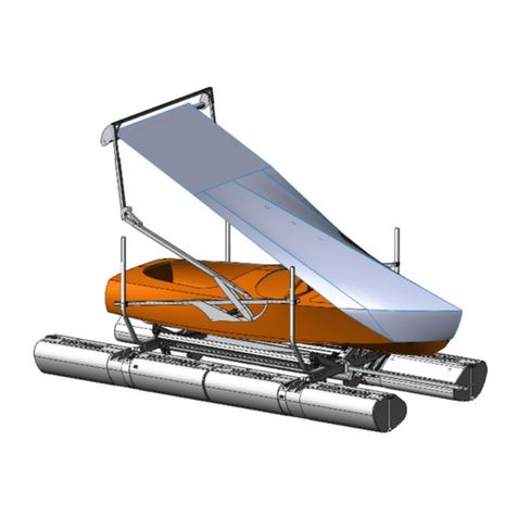
Sunstream SWIFTSHIELD A Series User manual

FORM NO. 660843 REV. B PAGE 1
READ CAREFULLY BEFORE ASSEMBLY AND USE.
KEEP THESE INSTRUCTIONS.
COPYRIGHT 2017 SUNSTREAM CORPORATION® - ALL RIGHTS RESERVED
A-SERIES
ASSEMBLY, INSTALLATION AND USE MANUAL
PILING LIFT
For: Most
Four Post
Piling Lifts
SS-AMP12124B
SS-AMP14136B

FORM NO. 660843 REV. B PAGE 2
TABLE OF CONTENTS
DISCLAIMER OF LIABILITY
These assembly and installation instructions have been provided by SunStream Corporation® at the
request of the potential installer and/or assembler. If you are not an authorized SunStream® Dealer and
are not a reasonably-skilled mechanic, please contact SunStream® so that we can refer you to a local
dealer who can skillfully and safely perform the assembly and installation of your SunStream® boatlift. It is
the potential installer and/or assembler’s responsibility to determine whether he or she has the necessary
skills, knowledge, and tools to properly and safely assemble and/or install the SunStream® lift described
herein. Improper assembly and/or installation may cause the lift to function improperly or not to function.
Improper assembly and/or installation may additionally cause a risk to personal safety or property.
If the assembler and/or installer is confused or has questions or concerns about a particular assembly
or installation, he or she should contact SunStream® by telephone at (253) 395-0500 before proceeding
further. The information contained in these instructions does not constitute a warranty or guarantee
of any kind.
An assembler’s and/or installer’s failure to correctly follow these assembly and installation instructions
constitutes a waiver of the assembler and/or installer’s rights against SunStream® regarding any
Subsequent damages to property or personal injury caused by the assembler’s and/or installer’s improper
Safety Instructions………………………………………………………3
Overview………………………………………………………………..4-5
Tools Required…………………………………………………………..6
Installation and Assembly
Bow Sprit………………………………………………………….7-10
Frame……………………………………………………………..11-29
Power Pack………………………………………………………….23
Installing and Adjusting the Cover………………………….30-36
Removing the cover……………………………………………38-40
Custom Trimming Roller and crossbeam………………….41-42
Quick Tips……………………………………………………………….43
Maintenance ……………………………………………………………44
Troubleshooting………………………………………………………..45
Accessories……………………………………………………………..46
Warranty……………………………………………………………. 47-48

FORM NO. 660843 REV. B PAGE 3
IMPORTANT SAFETY INSTRUCTIONS
If you have any questions, please call your dealer, or SunStream® at (253)395-0500
Save These Instructions
Your safety and the safety of others is very important. Proper use of the information in
this manual will help avoid potential hazards that could cause damage to property
and/or personal injury. It is not possible, however, to identify and warn users of
all hazards associated with the assembly, installation, operation, and maintenance of
the SwiftShield A-SeriesTM. You must use your own good judgment.
SAFETY WARNINGS
Failure to comply with the following rules may result in severe injury and/or death
and damage to property. Misuse of your lift may cause the lift and boat to become
unstable.
1. Your SwiftShield™ is a piece of heavy equipment and the act of covering and uncovering
your boat should be treated with respect and good judgment. Children should not operate the
cover without strict adult supervision.
2. When operating the cover mechanism, keep limbs and fingers away from any possible pinch
points.
3. Restrict Children and Adults from playing near the SwiftShield™ mechanism.
4. Before operating the SwiftShield™, be sure that nothing will interfere with it’s operating path.
5. Do not hang from cover mechanism and or add any additional weight to the system.
6. Be sure that the Boat is positioned properly on the boat lift. If boat is not positioned correctly,
the SwiftShield™ mechanism could strike the boat causing damage.
7. Make sure hydraulic lines are clear from any pinch points before operating the SwiftShield™
Mechanism.
8. When Operating the SwiftShield™, be sure to keep an eye on the cover so that it does not
get caught on any part of the boat. If the fabric gets caught it could tear.
9. When operating the SwiftShield™, be sure that the mechanisms arms do not interfere with
any boat guide-ons.
10. Do not use the power pack for storage purposes. Articles or tools in box could cause damage
to the pump or electrical items.
11. SunStream®recommends not operating the SwiftShield™ in winds above 25mph .
12. SunStream®recommends securing your cover by the tie down points when winds are
between 40mph-70mph.
13. SunStream®recommends removing your cover when winds are to exceed 70mph.
NOTICE:
WARNING:

FORM NO. 660843 REV. B PAGE 4
SwiftShield™
Overview
SwiftShield™ Cover
Roller Tube
Bow Sprit
Guide Ropes
Cross Bar
I-Beam
Hanger
Cylinder
Side
Rail
Piling
Piling Lift I-Beam
Guide Post
Bow Sprit
Spreader Pipe
Upper Arm
Fin Plate
Cylinder Mount
Tube
Side Rail
Clamp

FORM NO. 660843 REV. B PAGE 5
SwiftShield™
Overview
Continued
*Lines shown disconnected
Battery
Power Pack Box
RC Unit
Hydraulic Pump Hydraulic Lines*
from SwiftShield™
Cylinders
SunFluid
Reservoir

FORM NO. 660843 REV. B PAGE 6
ASSEMBLY INSTRUCTIONS
If you have any questions during the assembly process, please call your local dealer or
SunStream® at (253) 395-0500.
SunStream® recommends at least 2 people for assembly.
Before beginning assembly, find a nice flat area with room to work and set up your parts. Read
ahead to the installation procedure to determine the best location to start.
Tools Required:
SunStream® recommends the tools below for easier and quicker assembly.
Box Knife (to open packaging)
9/16” Socket
3/4” Socket
7/8” Socket, or adjustable wrench
1” Socket, or adjustable wrench
Socket wrench
Torque wrench (ft-lbs)
1/2” Combination wrench
9/16” Combination wrench
3/4” Combination wrench
32mm Open end wrench, or adjustable wrench
Pipe wrench with at least 2” opening
Diagonal cutters
Hacksaw
Mallet
Anti-Seize (to be used on all threaded fasteners)
Cable ties
3/16” Allen wrench
7/32” Allen wrench
Needle nose pliers
Snap ring pliers
Large Flat head screw driver
Tape measure
Recommended Tools:
Cordless drill
13/32” drill bit
Small adjustable wrench
Level
SunFluid
Torque values: 3/8-16 SS Bolt 20 lb-ft

FORM NO. 660843 REV. B PAGE 7
1-A
Assembling the Bow Sprit Clamp
Step 1
Assembling and Installing the Bow Sprit
Insert aft clamp into long
forward tube

FORM NO. 660843 REV. B PAGE 8
1-B
Clamping the Bow Sprit to the I-Beam
Steps:
1. Bow Sprit to be centered between the bunks.
2. Apply anti-seize to bolt threads before installing nuts.
3. Clamp bow sprit to I-beam with bolts and nuts.
Bolt SS, 3/8-16 X 8”,
Fully Threaded
4 Places
Nut SS, Nylok,
3/8-16, 4 Places

FORM NO. 660843 REV. B PAGE 9
1-C
Inserting the Bow Sprit forward tube
Bolt SS
3/8-16 X 3.5”
Nut SS
Nylok 3/8-16
Steps:
1. Insert bow sprit extension into bow sprit.
2. Apply anti-seize to bolt threads before
installing nut.
3. Final length to be determined after roller
has been installed.
Bow Sprit Extension
Bow Sprit

FORM NO. 660843 REV. B PAGE 10
1-D
Inserting and securing the Spreader Pipe
Spreader Pipe
Cotter Pin, SS
2 Places
Steps:
1. Insert spreader pipe into hole in bow sprit
extension.
2. Lock in place with cotter pins

FORM NO. 660843 REV. B PAGE 11
Step 2
Assembling and Installing the SwiftShield™ Frame
Important:
Repeatable boat position on the lift is important when using the SwiftShield™. The
boat must be lifted in the same position every time. Positioning the boat too far for-
ward, or too far aft could result in damage to the cover or the boat.
To achieve a repeatable position of the boat on the lift, SunStream®recommends
using an indicator or reference point on the hull or rub rail of the boat to ensure repeat-
able boat position.
The center of Gravity (CG) of the boat should be centered above the bunks. Typically
this is when the transom is 6” to 18” off the end of the bunks. This usually depends on
engine configuration.
Bow Sprit
Bunks
SwiftShield™
Arm
I-Beam
FWD
Side Rail Side Rail
Clamps
Wind Guide
Fin Plate

FORM NO. 660843 REV. B PAGE 12
2-A
Side Rail, Cylinder Mount Tube and Side Rail Clamps
SIDE RAIL
CYLINDER MOUNT
TUBE
Steps:
1. Locate end of side rail with hole 2.75” from end. Ensure it is facing forward.
2. Insert cylinder mount tube on side rail, as shown, with large plate facing forward.
3. Slide side rail clamps onto each end of side rail as shown.
4. Apply anti-seize to bolt threads before installing nuts.
5. Bolt the forward side rail clamp to the first hole in the side rail as shown. (The other
three side rail clamps are not bolted to side rail.)
6. Repeat on opposite side of lift.
2.
2.75”
FWD
Bolt SS,
3/8-16 x 3.5”
2 Places
Nut SS
Nylok 3/8-16
2 Places
5.
Side Rail Clamp
4 Places
Large plate must
face forward
FWD I-BEAM
AFT I-BEAM
3.
FWD
Note: Remove Cross Bar, packaged inside Side Rail.

FORM NO. 660843 REV. B PAGE 13
2-B
Installing Side Rails with Side Rail Clamps
Steps:
1. With the side rail clamps in place, locate side rail inside pilings and outside of guide
posts.
2. Apply anti-seize to bolt threads before installing nuts.
3. Use bolts and nuts to clamp in place as shown above. Leave bolts loose until side rails
are properly located in the next step.
4. Repeat on opposite side.
Bolt SS,
3/8-16 x 8”
8 Places
Nut SS
Nylok 3/8-16
8 Places
FWD
Guide Post
Piling

FORM NO. 660843 REV. B PAGE 14
2-C
Locating Side Rails on I-Beams
STANDARD WIDTH 61.75”
WIDE WIDTH 68”
Mount Side Rails
to I-beam, between
Guide-Posts
and Pilings
Guide-Posts
I-Beam
Hangers
STANDARD WIDTH 123.5”
WIDE WIDTH 136”
Steps:
1. Place side rails outside guide
posts at appropriate distance
from center.
2. Properly torque all nuts.
Pilings
Confirm lift motors and
wiring do not interfere with
SwiftShield™ arms.
Guide Posts

FORM NO. 660843 REV. B PAGE 15
* Bow sprit not shown.
2-D
Counter Balance Weights
Steps:
1. Slide concrete counter balance weights onto aft end of side rails, as shown.
STANDARD version requires 2 weights per side rail.
WIDE version requires 3 weights per side rail.
2. Apply anti-seize to bolt threads before installing nuts.
3. Lock in place with bolts and nuts as shown.
4. Properly torque all nuts.
5. Repeat on opposite side.
Nut SS,
3/8-16
4 Places
Bolt SS,
3/8-16 x 3”
4 Places

FORM NO. 660843 REV. B PAGE 16
2-E
Finding Midpoint of Boat
Pinning the Cylinder Mount Tube in place
Steps:
1. Using a tape measure, determine overall length of the boat, including swim plat-
form, if equipped.
2. Locate the midpoint between the bow and stern of the boat.
3. With the boat in the standard position on the lift, adjust cylinder mount tube so that
forward lug hole aligns with the midpoint of the boat.
4. Apply anti-seize to bolt threads before installing nut.
5. Using the bolt and nut, lock cylinder mount tube into position on side rail, as shown.
You may need to adjust this position later.
6. Repeat on opposite side.
3.
5. Forward Lug on
Cylinder Mount
Tube
Nut SS,
3/8-16
2 Places
Bolt SS,
3/8-16 x 3”, 2 Places

FORM NO. 660843 REV. B PAGE 17
2-F
Installing Lower Arms
Steps:
1. Align end of lower arm with forward lug on cylinder mount tube.
2. Apply grease to pin and install with washers and cotter pins. Bend cotter pins.
3. Repeat on opposite side.
Side Rail
Lower Arm
Cylinder
Mount Tube
FWD
* Bow sprit not shown.
Pin .75” x 4.5”
2 Place
Washer .75”
4 Places
Cotter Pin
4 Places
Forward Lug
Lower Arm

FORM NO. 660843 REV. B PAGE 18
Temporarily
bolt in place
Lower Arm
Upper Arm
2-G
Installing Upper Arms
Steps:
1. Insert upper arm into lower arm, on starboard side first.
2. Apply anti-seize to bolt threads before installing nuts.
3. Temporarily bolt in place with 3/8” bolt and nut. Continue to step 2-H.
4. Repeat on opposite side of SwiftShield™ after completing step 2-I.
FWD
* Bow sprit not shown.
Nut SS Nylok 3/8-16
2 Places
Upper
Arm
Lower
Arm
3. Bolt SS
3/8-16 x 3”
2 Places
Cross Beam
mounting holes

FORM NO. 660843 REV. B PAGE 19
2-H
Installing the Starboard Fin Plate
Steps:
1. Apply anti-seize to all bolt threads before in-
stalling nuts.
2. Install fin plate with pin, using nuts and bolts on
starboard arm only.
3. Properly torque nuts on fin plate.
Bolt SS,
3/8-16 x 3”
2 Places Nut SS,
Nylok 3/8-16
2 Places
Fin Plate
with Pin

FORM NO. 660843 REV. B PAGE 20
2-I
Adjusting Arm Length
Steps:
1. From dock, manually actuate arm back and forth to determine optimal length of arm
and position of cylinder mount tube.
2. End of upper arm should extend 12” to 14” beyond the furthest point on the bow, includ-
ing anchor, if equipped.
* Boats longer than 30’ (or if dock interferes) may require end of arm to be above and be-
hind bow.
3. End of the upper arm must extend 12” to 14” beyond the furthest point on the stern, in-
cluding swim platform, if equipped. Top of roller should be at top of swim platform.
4. When optimal arm length is determined, lock in
place with bolt and nut through appropriate holes in
the upper and lower arms.
5. Apply anti-seize to all threads before installing nuts.
6. Properly torque all nuts.
7. To achieve equal distance from the bow and stern,
you may need to adjust the pivot location by moving
the cylinder mount tube. Refer back to step 2E.
8. Repeat on opposite side of SwiftShield™.
Bolt SS
3/8-16 x 3”
2 Places
Nut SS Nylok 3/8-16
2 Places
Upper
Arm
Lower
Arm
4.
12”-14” 12”-14”
Range of possible
forward Roller positions *
Other manuals for SWIFTSHIELD A Series
1
This manual suits for next models
2
Table of contents
Other Sunstream Lifting System manuals