6.2. Fixed Wing UAV.........................................................................................................................................................11th
VII. Software Operation........................................................................................................................................................... 11th
7.1. Two ways for changing the parameters.................................................................................................................... 11th
7.2. How to use the software...................................................................................................................................... 12th
7.2.1. Login..............................................................................................................................................................12th
7.2.2. RF Configuration...........................................................................................................................................13th
7.2.3. RS1 Configuration.........................................................................................................................................15th
7.2.4. RS2 Configuration.........................................................................................................................................16th
7.2.5. IP New Network Configuration.................................................................................................................... 17th
7.2.6. RF New NET Configuration......................................................................................................................... 17th
SUNTOR ELECTRONICS CO., LIMITED
I. Disclaimer
SUNTOR is the registered trademark of SUNTOR ELECTRONICS CO., LIMITED. All product names and brands
in this manual are trademarks or registered trademarks of the Company. SUNTOR ELECTRONICS CO.,
LIMITED reserves all copyrights of the product and the manual. All the information must not be copied or
reproduced in any form without permission of SUNTOR. There may be semantic differences between
disclaimers of different languages. The Chinese version shall prevail in Chinese mainland, while the English
version shall prevail in other regions. Thank you for purchasing SUNTOR ST20NPT. Please use ST20NPT
according to local radio regulations. Before using, please carefully read this disclaimer. Once the product is
used, all the contents of the disclaimer will be regarded recognized and accepted. Please install and
operate the product in strictly accordance with the requirements of this manual. SUNTOR ELECTRONICS CO.,
LIMITED and its affiliates will not assume any legal responsibility for results or losses caused by improper
use, installation, assembly and modification (including the use of non-specified SUNTOR parts and
accessories, such as the radio power amplifier, antenna and SMA extension cord).
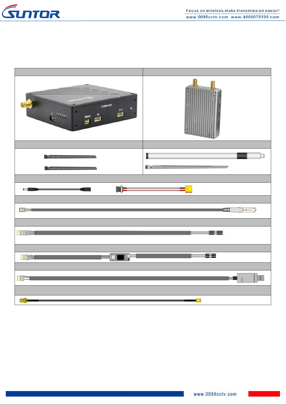
II. Precautions for integration
1) Be sure to use the parts provided by SUNTOR.
2) Before powering on please make sure the antenna are in good connection and not install or remove
the antennas with power on.
3) Given that the carbon fiber body and metal load may have shielding effects on antenna signals, they
should not be installed between the antenna and ground terminal. Keep the antenna on board free
from winding or blocking by obstacles. The antenna end should be vertically downward without
bending to prevent shortening communication distance and failure communication.
4) Antennas on board should be kept away from other radio antennas to avoid electromagnetic noise and