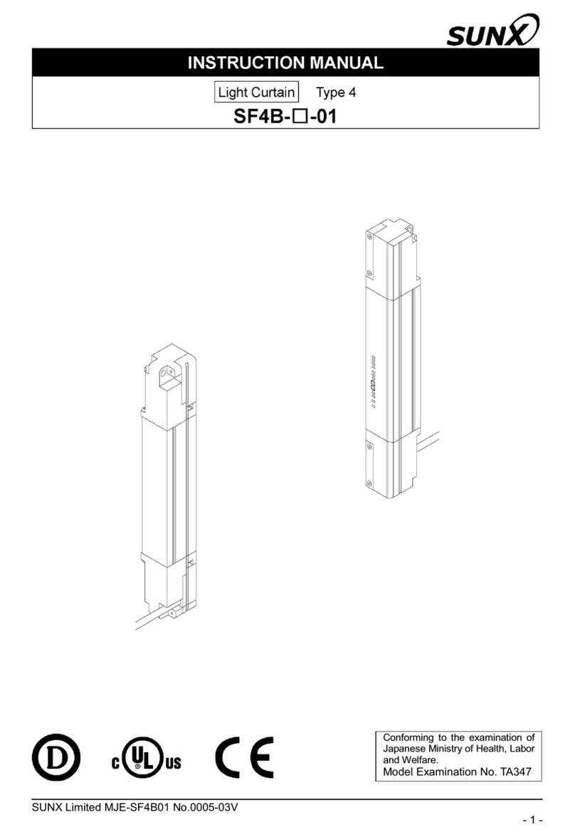
Sunx SF4B User manual

SF4BSERIES
The SUNX’ light curtain uses new concepts and
combines even greater safety
with higher productivity
SF4BSERIES
LIGHT CURTAIN Type4
JIS
mImage picture
Conforming to
OSHA / ANSI
Conforming to Machine
Directive & EMC Directive
Approved Listing
"14 mm (0.551 in) Finger sensing
"25 mm (0.984 in) Hand sensing
"45 mm (1.772 in) Arm / Foot sensing
LIGHT CURTAIN

Minimum sensing object
"45 mm
"1.772 in
(40 mm 1.575 in beam pitch)
Minimum sensing object
"14 mm
"0.551 in
(10 mm 0.394 in beam pitch)
Minimum sensing object
"25 mm
"0.984 in
(20 mm 0.787 in beam pitch)
1
New concepts in design driving toward
greater safety and higher productivity
SF4BSERIES
SF4BSERIES
SF4BSERIES
SF4BSERIES
SF4BSERIES SF4BSERIES
Greater maintenance efficiency!
Supports both PNP and NPN polarities
The single model is universally compatible to
improve maintenance efficiency.
Less setup time for safety circuits
Adoption of a special control unit
Safety circuits can be installed and configured easily.
Contributes to
miniaturization of
machinery
MinimMinimum sensing objectum sensing object
size is "14 mm (0.551 in)14 mm (0.551 in)
FingFinger prer protection type appearotection type appear
Safety distance greatly shortened
to improve productivity
Reduces losses in
line utilization rate
Incorporates advanced
ELCA function
Reduces malfunction due to mutual
interference and extraneous light
Greater maintenance efficiency!
Supports both PNP and NPN polarities
The single model is universally compatible to
improve maintenance efficiency.
Less setup time for safety circuits
Adoption of a special control unit
Safety circuits can be designed and constructed easily.
Contributes to
miniaturization of
machinery
Minimum sensing object
size is "14 mm (0.551 in)
Finger protection type appear
Safety distance greatly shortened
to improve productivity
Reduces losses in
line utilization rate
Incorporates advanced
ELCA function
Reduces malfunction due to mutual
interference and extraneous light
Avoids line stoppages when a
workpiece passes through
Muting unit function is bMuting unit function is built into light curtain
Productivity maintained bProductivity maintained by muting function
Avoids line stoppages when a
workpiece passes through
Muting unit function is built into light curtain
Productivity maintained by muting function
P.5
P.3
P.9
P.11
P.7
The high level of resistance to disturbance from extraneous light that was a basic feature of the SF4-A series has
been maintained in this new series, but a variety of new concepts have been incorporated into the new series,
including more compact machine tool size due to a reduction in the safety distance, muting control circuits which
have been built into the light curtain, and an override function that allows the manufacturing line to restart operation
after the line has stopped even while muting control was active.These functions all contribute to a light curtain that
provides greatly improved safety with no losses in productivity.
New Concepts
from SUNX
Combining Greater
Safety and Higher
Productivity !
New Concepts
from SUNX
Combining Greater
Safety and Higher
Productivity !

Minimum sensing object
"45 mm
"1.772 in
(40 mm 1.575 in beam pitch)
Minimum sensing object
"45 mm
"1.772 in
(40 mm 1.575 in beam pitch)
Minimum sensing object
"14 mm
"0.551 in
(10 mm 0.394 in beam pitch)
Minimum sensing object
"14 mm
"0.551 in
(10 mm 0.394 in beam pitch)
SF4B-FSF4B-HSF4B-A
Minimum sensing object
"25 mm
"0.984 in
(20 mm 0.787 in beam pitch)
Minimum sensing object
"25 mm
"0.984 in
(20 mm 0.787 in beam pitch)
Finger protection type
Hand protection type
Arm / Foot protection type
Flexible cable
releasing
2
Flexible cable
releasing
Greater maintenance efficiency!
Supports both PNP and NPN polarities
The single model is universally compatible to
improve maintenance efficiency.
Less setup time for safety circuits
Adoption of a special control unit
Safety circuits can be installed and configured easily.
Contributes to
miniaturization of
machinery
Minimum sensing object
size is "14 mm (0.551 in)
Finger protection type appear
Safety distance greatly shortened
to improve productivity
Reduces losses in
line utilization rate
Incorporates advanced
ELCA function
Reduces malfunction due to mutual
interference and extraneous light
Avoids line stoppages when a
workpiece passes through
Muting unit function is built into light curtain
Productivity maintained by muting function
mEnlargement
Only 5mm 0.197 in from the
center of the first beam channel
to the edge of the light curtain
(Arm / Foot protection type has 15 mm 0.591 in)

Up to a maximum 3 sets can be connected in series
A wide range of variations are available with protective heights of
230 to 1,910 mm 9.055 to 75.197 in (1,270 mm 50.000 in for the
finger protection type). Optional cable for series connection can be
used to connect up to a maximum of 3 sets (maximum 192 beam
channels) in series. The reduced amount of wiring needed lowers
costs and also helps to prevent interference.
m
This is the characteristic safety distance for the light curtain as defined by ISO 13855.Calculate the safety distance by including the machinery’s maximum stopping time.
Furthermore refer to the relevant standards of the region where this device is to be used, and then install this device.
Maximum 1,910 mm
75.197 in
Minimum 230 mm 9.055 in
●
Up to 3 sets can be connected in series!
●
Cables for series connection are available
●
in lengths of up to 5 m 16.404 ft!
●
Cables for series connection are available
in lengths of up to 5 m 16.404 ft!
●
Series connection of different types is possible.
Arm / Foot protection type
(Presence sensing)
Hand protection type
(Intrusion detection)
Safety
distance
A fast response time of 14 ms has
been achieved regardless of the
number of beam channels, the
beam axis pitches and the number
of units connected in series. This
reduces calculation work required
for the safety distances.
Hand protection type
(20 mm 0.787 in pitch)
To control
circuits
Characteristic distance
for the machinery’s
maximum stopping time
Maximum 122 mm 4.803 in greatly shortened
Mounting position of previous model
Characteristic safety distance for equipment
Characteristic safety distance for light curtain
Safety distance
Same response
time of
14 ms
SF4B Finger protection type
(10 mm 0.394 in pitch)
Mounting position of SF4B
Contributes to
miniaturization of machinery
Safety distance greatly shortened to improve productivity!
A finger protection type model improves productivity and
reduced on-floor costs in line with more compact machinery.
The finger protection type can detect very small objects with diameters of as small as 14 mm
0.551 in, so that the safety distance based on the ISO 13855 international standard has
been shortened from previous models to a maximum of 122 mm 4.803 in.
With production machinery becoming more compact,
this helps contribute to improved productivity and
more efficient utilization of space.
Minimum sensing object "14 mm "0.551 in Finger protection type appear
Safety distance
Maximum 122 mm
(4.803 in)
shortened
Safety distance greatly shortened to improve productivity
Previous model
● Finger protection
type: 28 mm 1.102 in
● Hand protection
type: 116 mm 4.567 in
m
m
()
Max. 5,730 mm
225.590 in when
connecting 3 units
in series
3

SF4B
Dead zone
(required protective cover)
Overlapped
mounting
Overlapped
mounting
Dead zoneless
mounting bracket
MS-SFB-3 (Optional)
Unit length protective height, so mounting is possible with no dead zone.
‘ZERO’dead zone
Unit length protective height, so that no dead zone can occur in the interfaces between light curtains when units are
connected in series.
The equipment can be used with confidence because there are no dangerous openings resulting from dead zone.
Mounting brackets that support ‘ZERO’dead zone
Special brackets are available to mount the units in order to create ‘ZERO’
dead zone. Workability is excellent because mounting and beam axis
alignment are possible from the front of the light curtain.
●
Cables for series connection are available
●
in lengths of up to 5 m 16.404 ft!
●
‘ZERO’dead zone when using series mounting
●
‘ZERO’dead zone when using L-shaped setups
(Except for finger protection type)
●
Overlapped mounting when using
L-shaped setups
●
Dead zone when using series mounting
Gaps occurred at connecting point
This required mounting of protection covers or
overlapped mounting of light curtains.
P.5
P.7
P.9
P.12
New concept
New concept
Previous model
Contributes to
miniaturization of machinery
Avoids line stoppages when
a workpiece passes through
Reduces losses in line
utilization rate
Greater maintenance
efficiency!
Less setup time for safety
circuits
4

Safety relay unit External device
(Force-guided relay, etc.) Motor, etc.
Motor, etc.
Light curtain
Monitor
Reset input
Monitor
S
F
4
B
Muting sensor
CX-400 series
Muting
lamp
Light curtain
SF4B series
Reset input
● Avoiding line stoppages when a workpiece passes through
The light curtain has a built-in muting function that causes the light
curtain to ignore workpiece when two or more of the four muting
sensors are interrupted simultaneously as a result of a workpiece
passing by.This prevents the line from stopping when a workpiece
passes through the light curtain, thereby maintaining productivity.
When a person passes through the light curtain, two or more of
the muting sensors are not interrupted, and so the muting function
is not activated.
SF4B series
Built-in external
device monitoring
function
Built-in external
device monitoring
function
External device
(Force-guided relay, etc.)
New concept
New concept
Reduces
Total
Cost!
Others
Safety relay
unit
SF-AC
Muting unit
Light curtain
Others
Light curtain
Muting unit function is built into light curtain
Productivity maintained by muting control function
No safety
relay unit needed
Smaller control
board
Does not comply with safety standards
SF4B
Complies with safety standards, but high cost and uses large amount of space
Muting sensor
Muting sensor
●Circuit with unreliable PLC
●High-cost circuit with exclusive units
PLC
Light curtain
Light curtain
Muting unit
External device
(Force-guided relay, etc.)
Motor, etc.
Motor, etc.
External device
(Force-guided relay, etc.)
Motor, etc.
Muting sensor
Safety
relay unit
Avoids line stoppages when
a workpiece passes through
The light curtain is equipped with a muting control function that causes the line to stop only when a person passes through the light curtain,
and does not stop the line when a workpiece passes through.The muting sensors and muting indicators can be connected directly to the light
curtain, so that a special controller is not required for muting.This both reduces costs and increases safety and productivity.
Is the circuit designed to suspend the light curtain from responding when
a workpiece passes through it?
A muting control function is provided to increase both safety and productivity.
All in One!!
No special unit needed
Complies with safety standards
Saves space
SF4B series
&
SF4B series
Previous model
External device
Force-guided
relay, etc.
( )
Equipped with a safety circuit that does not require a exclusive safety relay unit
The light curtain has a built-in external
device monitoring function (such as for
fused relay monitoring) and an interlock
function.The safety circuit is constructed so
that a separate safety relay unit is not
needed, and the control board is also more
compact, which both help contribute to
lower costs.
The safety relay unit capability is built into the light curtain, so component costs can be reduced.
Previous model
5

SF4B
SF4B
SF4B
Built-in external
device monitoring
function
When line stopped
before muting condi-
tions were established
(2 sensors interrupted)
Removal operation
unnecessary
Removal operation
unnecessary
Removal operation required
When power turns off
while light curtain was
interrupted
Removal operation
unnecessary
Removal operation
unnecessary
Workpiece must be
removed before restart
Smooth restart
Smooth restart
Motor, etc.
Previous model
Reduces
Total
Cost!
Reduces
Total
Cost!
OthersOthers
Safety relay
unit
SF-AC
Safety relay
unit
SF-AC
Muting unitMuting unit
Light curtainLight curtain
OthersOthers
Light curtainLight curtain
In case of using muting control function
Then
Then
External device monitor
Muting sensor
Muting unit
Safety relay unit
Muting lamp
SF4B series
Unnecessary
Unnecessary
External device
(Force-guided relay, etc.)
P.3
P.7
P.9
P.12
SF4B series
Separate muting control function for each beam channel improves safety
For example, depending on the height of the workpiece, the muting function can be activated
for 10 beam channels starting from the bottom, so that if the 11th or subsequent beam
channels are interrupted, it is judged that a person has entered the area and the line stops.
In case the power turns off while the light
curtain has been interrupted by a workpiece
or in case the line stops before the muting
conditions have been established (if only
one muting sensor has been interrupted),
the machinery can be restarted. With the
special units used previously, muting control
was not allowed after a workpiece had
interrupted the light curtain. So, the
workpiece needed to be removed before
the line could be restarted. However, the
override function allows the line to be
restarted smoothly without having to
remove the workpiece that is interrupting
the light curtain.
Override function allows the line to be restarted smoothly after it has stopped while muting control was active
While muting control is active (line operating)
Line stopped
The SFB-HC* Handy-Controller (optional,
refer to p. 11) can be used to carry out
muting control for specified beam channels
only. Because individual beam channels
can be specified to suit the workpiece,
separate guards to prevent entry do not
need to be set up.
* A Handy-controller cannot be used with
the SF4B-□-01 (refer to p.14) and
SF-C14EX-01. (refer to p.43)
Previous model
Contributes to
miniaturization of machinery
Avoids line stoppages when
a workpiece passes through
Reduces losses in line
utilization rate
Greater maintenance
efficiency!
Less setup time for safety
circuits
6

Normal operation
Breaking out error
Digital error
indicator
‘6’is a shield wiring problem.
Check the shield wiring
again to see if it's correct.
‘6’appears on the
light curtain
••••
Front protection
cover
Maintenance is easy
simply by replacing
the cover
This prevents the sensing surfaces from
being damaged if the workpieces hit the
light curtain. (optional)
Light curtain is protected to prevent problems
Protection bar protects the sensing
surfaces from impacts from objects sensed
This can be used to protect the sensing surfaces even
if the light curtain is set up in harsh environments such
as places where welding spatter occurs.(optional)
Front protection cover
protects the sensing surfaces
Reduces losses in line
utilization rate Incorporates advanced ELCA function
The advanced ELCA function used in the SF4-A that has been widely
acclaimed by the marketplace has also been adopted into the SF4B in
order to suppress mutual interference and the effects of extraneous light.
Stops line operating losses before they happen
Revolving light
Reduces malfunction due to mutual interference and extraneous light
Obstruction sensorObstruction sensor
Revolving light
●
Mutual interference is reduced without
need for interference prevention lines
The light curtain is equipped with the ELCA
(Extraneous Light Check & Avoid) function
which has already gained strong approval in
the marketplace for its powerful suppression
of mutual interference between light
curtains. Because it automatically shifts the
scan timing of the light curtain in order to
avoid interference, it is not necessary to
wire interference prevention lines between
machineries, so that the light curtains can
be positioned with much greater flexibility.
●
Reducing the number of malfunctions
caused by extraneous light
A double scanning method and retry processing
are two new functions exclusive to SUNX that
have been established in the workplace as
being effective in eliminating the effects of
momentary extraneous light from peripheral
equipment. The reduction in operating errors
caused by extraneous light reduces frequent
stopping of machinery and helps to prevent
losses in line operating efficiency.
The system constantly checks the light curtain for problems such as incorrect cable wiring,
disconnection and short-circuits, and also for internal circuit problems and incoming light
problems. If a problem should occur, the same output (OFF signal) as when the object was
detected is maintained in order to ensure safety, and the details of the error appear on the
digital display.
The error details can be checked at a glance without the inconvenience of the previous
method of counting the number of LED blinks, so that smooth support is possible if problems
occur at startup and during maintenance operations, even if assistance is given via
telephone.
Supports resolution of electrical problems when starting up lines
Equipped with a digital error indicator so that error details can be understood at a glance!
Beam-axis alignment
indicator
Stability
indicator
Hexagon-socket
head bolt for
alignment
(360rotation for every 30)
360 rotation
when used with
hexagon-socket
head bolt for alignment
7

A
B
C
D
OSSD
Blinking
STB
A
B
C
D
OSSD
Light
up
STB
A
B
C
D
OSSD
Light
up
STB
A
B
C
D
OSSD
STB
4 block3 block2 block1 block
P.3
P.5
P.9
With SF-LAT-2N (optional) Laser Alignment Tool, the beam axes alignment can be quickly
and easily performed using the easy-to-see laser beam spot, even when light curtain units
are installed long distances apart. In addition, as the SF-LAT-2N Laser Alignment Tool is
battery-operated; beam axes alignment can be performed before actual powering on of the
light curtain itself.
The bottom two LEDs‘C, D’
light up in red
Furthermore, STB display
allows the most stable incident
light statusmto be confirmed.
Hexagon-socket
head bolt for beam
axis alignment
(up to 15)
Offset and swing of light curtain emitters
and receivers can be seen easily.
Alignment of beam axes can be accurately performed prior to power-up SF-LAT-2N
Allen wrench
1The topmost channel beam axis is
correctly aligned
2The bottommost channel beam axis is
correctly aligned Offset Swing
P.12
m
140 % or more incident light intensity
of control output operation level
Revolving light
Obstruction sensor
Beam-axis alignment indicators display the beam channels of the light
curtain in four blocks. When the beam channel at the bottommost channel
(or topmost channel) that is used as a reference for beam-axis alignments
correctly aligned, the LED blinks red. After this, each block lights red as the
beam axes successively become aligned, and when all channel beam axes
are aligned, all LEDs light green. The display also has a stability indicator
(STB) added so that setup can be carried out with greater stability too.
Convenient tool facilitates easy beam-axis alignment
Reduces installation time significantly
The beam-axis alignment indicators that incident light position can be seen at a glance
Beam channels are
displayed in 4 blocks The bottommost channel
beam axis is aligned
Only the beam axes of the
two lower blocks are aligned
All channel beam axes
are aligned
Beam-axis alignmentBeam-axis alignment
indicator
Beam-axis alignment
indicator
Stability
indicator
Stability
indicator
The bottommost LED ‘D’
is blinking red
All LED ‘A to D’
light up in green
The hexagon-socket head bolts on the
mounting brackets for aligning the beam
axis can be tightened from in front of the
light curtain, so that work can be carried out
easily while checking the hexagon-socket
head bolt positions. This makes it much
easier to adjust the light curtain angles
when carrying out beam-axis alignment and
greatly improves ease of installation work.
Greatly improving ease of
installation working
Hexagon-socket
head bolt for
alignment
(360(360rotation frotation for eor everery 30y 30)
360 rotation
when used with
hexagon-socket
head bolt for alignmentor alignment
360rotation
when used with
hexagon-socket
head bolt for alignment
Hexagon-socket
head bolt for
alignment
(360rotation for every 30)
Contributes to
miniaturization of machinery
Avoids line stoppages when
a workpiece passes through
Reduces losses in line
utilization rate
Greater maintenance
efficiency!
Less setup time for safety
circuits
8

SF4B
mAs of June 2005 and based on
research conducted by SUNX.
Greater maintenance efficiency!
Supports both PNP and NPN polarities
The single model is universally compatible to improve
maintenance efficiency.
Use anywhere
in the world
In Europe, America and Asia
PNP output and NPN output
in a single model !
JIS
Conforming to
OSHA / ANSI
Conforming to Machine
Directive & EMC Directive
Approved Listing
●
A single model has universal applicability
The SF4B series combines PNP transistor
output and NPN transistor output in a single
model. Overseas equipment that uses PNP,
replacement with NPN sensors, factories
that are positively grounded, and transfer of
equipment overseas are all situations
where the control circuits for a single model
are suitable for use worldwide.
Universal design that can be used anywhere in the world
Supports both PNP and
NPN polarities in a single model
PNP output light curtain
PNP circuit
NPN output light curtain
NPN circuit
PNPPNP NPNNPN PNP /NPN
Switch between PNP /
NPN by changing wiring
PNP circuit NPN circuit
A single model is enough!
Different model is required
Previous model
●
Polarity can be changed easily by changing wiring
When the output polarity setting wire (shielded) is connected to 0 V,
PNP output is selected, and when it is connected to 24 V, it switches
to NPN output.
PNP / NPN
polarity indicator
PNP circuit
NPN circuit
Output polarity setting wire
(Shield)
0 V
24 V
Output polarity setting wire (Shield)
Connect to 0 V
Connect to 24 V
Not connected / open
PNP output
NPN output
Error
Control output (OSSD)
PNP or NPN side
lights depending on
which is selected.
SF4B series
9

Adapter cable
Adapter bracket
Currently-used connector
cable can still be used
To control
circuits To control
circuits
P.3
P.5
P.7
SF4B
P.12
Light curtain
currently in use
PNP NPN
Adapter cables and pitch adapter bracket are available to make it much easier to replace the wiring when changing over from SF4-A series
and SF2-EH series to a new series (Note 1). Mounting holes and control circuit connector cables do not need to be changed, and replacement
with SF4B series components can be carried out smoothly and there is no need to use replacement parts for previous models, so registration
can be only SF4B series (components).
Notes: 1) The pitch adapter bracket can not be used with the SF4-AH8(-N) only.
2) For details, please contact our office.
Supply of replacement parts, regardless of whether line is old or new
Adapter cables and adapter mounting brackets are available
so that previous peripheral devices for light curtains can still be used.
Light curtain currently in use
SF4B seriesSF4B series
New concept
New concept
Contributes to
miniaturization of machinery
Avoids line stoppages when
a workpiece passes through
Reduces losses in line
utilization rate
Greater maintenance
efficiency!
Less setup time for safety
circuits
10

Handy-controller
A variety of settings can be made to suit different applications
Safety circuits can be installed and configured easily
Handy-controller SFB-HC* that
enables the user to select a
variety of settings
The SFB-HC*(optional) Handy-Controller can be used to carry out
muting control for specified beam channels only. Because individual
beam channels can be specified, additional guards to prevent entry
do not need to be set up. (refer to p. 6.)
Separate muting control function for each
beam channel
SFB-HC
* A Handy-controller cannot be used with the SF4B-□-01 (refer to p.14)
and the SF-C14EX-01. (refer to p.43)
The SF4B series is equipped with a fixed blanking function that
allows specific beam channels to be selectively interrupted, without
causing the control output (OSSD) to output the OFF signal. This
function is convenient for use with applications in which certain fixed
obstacles always block specific beam channels.
Furthermore, this function provides greater safety, as the control
output (OSSD) will automatically output the OFF signal if the fixed
obstacles are subsequently removed from the sensing area.
Any valid beam channels can be selected!
The SF4B series incorporates a fixed blanking function.
1, 2 or 3 non-specified beam channels can be deactivated. If the
number of beam channels that are blocked is less than or equal to the
set number of beam channels, then the control output (OSSD) will not
output the OFF signal. This function is useful in the event that the
positions of obstacles within the sensing area must be changed during
workpiece rearrangement, or when workpiece go through the light
curtain’s sensing area.
Non-specified beam channels can be deactivated !
The SF4B series incorporates a floating blanking function.
Note:
When the floating blanking function is used, the size of the min.sensing object is changed.
Refer to ‘PRECAUTIONS FOR PROPER USE’(P.34) for details.
The output configuration of the auxiliary output can be changed.
Auxiliary output has selectable output configuration
This function reduces the amount of emitting
light. The two modes, normal mode and short
mode, can be selected. The factory setting is
set to the normal mode for the emission
intensity control function.
This function allows the user to confirm the
details of each light curtain setting.
Unless the password is not input, any setting
change of the light curtain cannot be allowed.
The factory setting is set to invalid for the
protect function.
Allows settings details to be copied into other
light curtains. In the event that the same
setting must be input into several different light
curtains, this function will reduce the time
required for the input of settings.
When the muting lamp diagnosis is disabled,
the muting function will continue to operate
even if the lamp is blown.
A variety of other functions can be selected
●
Emission intensity
control function
●
Setting monitoring
function
●
Protection function
●Copy function
●Muting lamp
diagnosis setting
Mode No. Description
0
1
2
3
4
5
6
7
8
9
Negative logic of the control output (OSSD 1, OSSD 2) (factory setting)
Positive logic of the control output (OSSD 1, OSSD 2)
For emission:output ON, For non-emission: output OFF
For emission:output OFF, For non-emission: output ON
For unstable incident beam: OFF (Note 1)
For unstable incident beam: ON (Note 1)
For muting: ON
For muting: OFF
For beam received: ON, For beam interrupted: OFF (Note 2)
For beam received: OFF, For beam interrupted: ON (Note 2)
The output cannot be used while the fix blanking function, floating
blanking function or the muting function is activated.
This device outputs the beam received / interrupted state under
activating the auxiliary output switching function using the handy
controller irrespective of activating other functions, fixed blanking
function, floating blanking function, and muting function.
Notes: 1)
2)
11

NPN
PNP
NPN
PNP
Auxiliary output
Safety output
Output polarity
selection switch
NPN
PNP
NPN
PNP
Slim
22.5 mm
0.886 in
P.3
P.5
P.7
P.9
SF-C10SERIES
Adoption of a special control unit
Safety circuits can be installed and configured easily.
Less setup time for safety circuits
A single unit can be used for PNP / NPN input switching,
reducing the number of parts that need to be registered.
Supports both PNP
and NPN polarities
Exclusive control unit is available for easy
design and construction of safety circuits
m
All models
Industry first
Industry first
Lead wire
Flat-tipped screwdriver
A spring method is used for the terminal
blocks for connections other than to the
light curtain. There is no need to control
tightening torques for these terminal blocks.
Easy setup requiring no
torque control
Connecting to the light curtain is done using
plug-in connections, which shortens setup
and replacement time.
Quick-connection Removable terminal blocks are used. This
reduces the work required for reconnecting
wiring during maintenance.
Removable terminal blocks
reduce maintenance time
Plug-in type control unit SF-C11
Removable!
Release button
Lead wire insertion hole
Ferrule (sleeve) terminal
(Please arrange separately.)
The strong metal enclosure has a built-in safety relay. It has an IP65
protective structure, so that it can be set up individually without
needing to be inserted into a control panel.
22.5 mm 0.886 in thickness, so can be inserted even into narrow
spaces inside panels.
Slim design
Robust type control unit SF-C12 Slim type control unit SF-C13
Metal enclosure with a IP65 protective structure
Connecting to the light curtain is done
using plug-in connector connections
IP65 Metal enclosure
Spring-type terminal block
No torque control needed
Robust
Slim
Contributes to
miniaturization of machinery
Avoids line stoppages when
a workpiece passes through
Reduces losses in line
utilization rate
Greater maintenance
efficiency!
Less setup time for safety
circuits
mAs of June 2005 and based on
research conducted by SUNX.
Uses a spring method
12

13
SF4B
2
3 4
1
7
2
5 6
1
7
Mounting bracket and connecting cable
are optional.
1
2
3
4
Component parts
Light curtain
Mounting bracket (Optional)
8-core bottom cap cable (Optional)
7Cable for series connection
(Optional, use for connect in series)
8-core extension cable
(Optional, use for cable extension)
Standard components (8-core cable)
1
2
5
6
Component parts
Light curtain
Mounting bracket (Optional)
12-core bottom cap cable (Optional)
7Cable for series connection
(Optional, use for connect in series)
12-core extension cable
(Optional, use for cable extension)
Muting control components (12-core cable, with interference prevention wire)
Required
Required
PRODUCT CONFIGURATION

14
SF4B
ORDER GUIDE
23
31
39
47
55
63
71
79
95
111
127
12
16
20
24
28
32
36
40
48
56
64
72
80
88
96
6
8
10
12
14
16
18
20
24
28
32
36
40
44
48
Finger protection type
Type Model No.
(Note 2) Number of
beam channels
Light curtains
Protective height
(mm in)
SF4B-F23
SF4B-F31
SF4B-F39
SF4B-F47
SF4B-F55
SF4B-F63
SF4B-F71
SF4B-F79
SF4B-F95
SF4B-F111
SF4B-F127
SF4B-H12
SF4B-H16
SF4B-H20
SF4B-H24
SF4B-H28
SF4B-H32
SF4B-H36
SF4B-H40
SF4B-H48
SF4B-H56
SF4B-H64
SF4B-H72
SF4B-H80
SF4B-H88
SF4B-H96
SF4B-A6
SF4B-A8
SF4B-A10
SF4B-A12
SF4B-A14
SF4B-A16
SF4B-A18
SF4B-A20
SF4B-A24
SF4B-A28
SF4B-A32
SF4B-A36
SF4B-A40
SF4B-A44
SF4B-A48
Appearance Operating range
(Note 1)
0.3 to 7 m
0.984 to 22.966 ft
0.3 to 9 m
0.984 to 29.528 ft
0.3 to 7 m
0.984 to 22.966 ft
0.3 to 9 m
0.984 to 29.528 ft
0.3 to 7 m
0.984 to 22.966 ft
Notes: 1) The ‘operating range’is the possible setting distance between the emitter and the receiver.The sensor can detect less than 0.3 m 0.984 ft away.
2) Models which have an ‘E’symbol in the model No. on the name plate are emitters, and those with a ‘D’symbol are receivers.
(Ex.) SF4B-F23 emitter: SF4B-F23E
SF4B-F23 receiver: SF4B-F23D
1
Mounting bracket and connecting cable are not supplied with the light curtain. Be sure to order them separately.
Beam pitch
Protective height
10 mm 0.394 in
5 mm
0.197 in
Beam
channel
No.
5 mm
0.197 in
Beam pitch
Protective height
20 mm
0.787 in
5 mm
0.197 in
Beam
channel
No.
5 mm
0.197 in
Beam pitch
Protective height
40 mm 1.575 in
15 mm
0.591 in
Beam
channel
No.
15 mm
0.591 in
Handy-controller non-compatible types
Some models that cannot use the SFB-HC Handy-controller (optional) are also available. Order models with ‘-01’at the end of the model No.
(Ex.) SF4B-F23 handy-controller non-compatible type:SF4B-F23-01
0.3 m
0.984 ft
Receiver cannot be
placed in this range
Emitter
Setting range of
the receiver
Actual operating
range of the sensor
Receiver Receiver
9 m 29.528 ft
(SF4B-F, SF4B-H72/H80/H88/H96, SF4B-A36/A40/A44/A48: 7 m 22.966 ft)
230
310
390
470
550
630
710
790
950
1,110
1,270
230
310
390
470
550
630
710
790
950
1,110
1,270
1,430
1,590
1,750
1,910
230
310
390
470
550
630
710
790
950
1,110
1,270
1,430
1,590
1,750
1,910
9.055
12.205
15.354
18.504
21.654
24.803
27.953
31.102
37.402
43.701
50.000
9.055
12.205
15.354
18.504
21.654
24.803
27.953
31.102
37.402
43.701
50.000
56.299
62.598
68.898
75.197
9.055
12.205
15.354
18.504
21.654
24.803
27.953
31.102
37.402
43.701
50.000
56.299
62.598
68.898
75.197
Hand protection type
Min. sensing object "14 mm
0.551 in (10 mm 0.394 in pitch)
Min. sensing object "25 mm
0.984 in (20 mm 0.787 in pitch)
Arm / Foot protection type
Min. sensing object "45 mm
1.772 in (40 mm 1.575 in pitch)

15
SF4B
ORDER GUIDE
Designation DescriptionModel No.
MS-SFB-1
Standard mounting
bracket
Pitch adapter
bracket
M8 mounting
bracket
M8 pitch adapter
bracket
Dead zoneless
mounting bracket
Mounting brackets
2Mounting bracket is not supplied with the light curtain. Be sure to order it separately.
Pitch adapter bracket
M8 mounting bracket M8 pitch adapter bracket
• MS-SFB-4
• MS-SFB-1-T • MS-SFB-4-T
Standard mounting bracket
M5 (Length: 16 mm 0.630 in)
hexagon-socket-head bolt
(Accessory for MS-SFB-1)
Standard mounting bracket MS-SFB-1
Pitch adapter
bracket
MS-SFB-4
M8 mounting
bracket
MS-SFB-1-T
M8 pitch adapter bracket
MS-SFB-4-T
M5 (Length: 16 mm 0.630 in)
hexagon-socket-head bolt
Light
curtain
• MS-SFB-1
Sensing
surface
Dead zoneless mounting bracket
• MS-SFB-3
M5 (Length: 25 mm 0.984 in)
hexagon-socket-head bolt
(Accessory for MS-SFB-3)
Dead zoneless mounting bracket MS-SFB-3
Spacer (Accessory for MS-SFB-3)
Light
curtain
Sensing
surface
Light
curtain
Sensing
surface
Light
curtain
Sensing
surface
Light
curtain
Sensing
surface
MS-SFB-4
MS-SFB-1-T
MS-SFB-4-T
MS-SFB-3
(Accessory for MS-SFB-4)
M5 (Length: 16 mm 0.630 in)
Hexagon-socket-head bolt
(Accessory for MS-SFB-1-T)
M5 (Length: 16 mm 0.630 in)
hexagon-socket-head bolt
(Accessory for MS-SFB-4-T)
Used to mount the light curtain on the rear surface and side
surface (4 pcs. per set for emitter and receiver)
Used as the mounting bracket when changing over a previous light
curtain with a protective height of 200 to 750 mm 7.874 to 29.528
in to the SF4B series. It is installed using two M5 hexagon-socket-
head bolts.(4 pcs.per set for emitter and receiver)
Allows the light curtain to be mounted at the rear and side with
one M8 hexagon-socket-head bolt. (4 pcs. per set for emitter and
receiver)
Used as the mounting bracket when changing over a previous
light curtain with a protective height of 200 to 750 mm 7.874 to
29.528 in to the SF4B series. It is installed using two M8 hexagon-
socket-head bolts. (4 pcs. per set for emitter and receiver)
Mounting with no dead zone is possible so that the mounting
bracket does not project past the sensing height.
(4 pcs.per set for emitter and receiver)
Four bracket set
Four M5 (Length: 16 mm
0.630 in) hexagon-socket-
head bolts are attached
Four bracket set
Four M5 (Length: 16 mm
0.630 in) hexagon-socket-
head bolts are attached
Four bracket set
Four M5 (Length: 16 mm
0.630 in) hexagon-socket-
head bolts are attached
Four bracket set
Four M5 (Length: 16 mm
0.630 in) hexagon-socket-
head bolts are attached
Four bracket set
Four M5 (Length: 25 mm
0.984 in) hexagon-socket-
head bolts and four spacers

16
SF4B
ORDER GUIDE
3 4 5
Connecting cable / Extension cable / Cables for series connection
6 7
Type DescriptionModel No.
Used for connecting to the light curtain and to other cables
or the SF-C13 control unit.
Two cables per set for emitter and receiver, Cable outer diameter: "6 mm "0.236 in
Cable color: Gray (for emitter), Gray with black line (for receiver)
The min. bending radius: R6 mm R0.236 in
Used for connecting to the light curtain and to other cables
or the SF-C13 control unit.
Two cables per set for emitter and receiver, Cable outer diameter: "6 mm "0.236 in
Cable color: Gray (for emitter), Gray with black line (for receiver)
The min. bending radius: R6 mm R0.236 in
Used for connecting to the light curtain and to an extension
cable or the SF-C11 control unit.
Two cables per set for emitter and receiver, Cable outer diameter: "6 mm "0.236 in
Connector outer diameter: "14 mm "0.551 in max.
Cable color: Gray (for emitter), Gray with black line (for receiver)
The min. bending radius: R6 mm R0.236 in
Used for connecting to the light curtain and to an extension cable or the SF-C12 control unit.
Two cables per set for emitter and receiver, Cable outer diameter: "6 mm "0.236 in
Connector outer diameter: "16 mm "0.630 in max.
Cable color: Gray (for emitter), Gray with black line (for receiver)
The min. bending radius: R6 mm R0.236 in
8-core bottom cap cable specifications.Used to allow
connector cables connected to previous light curtains (at the
control circuit side) to be smoothly adapted to the SF4B series.
Two cables per set for emitter and receiver, Cable outer diameter: "6 mm "0.236 in
Connector outer diameter: "16 mm "0.630 in max.
Cable color: Gray (for emitter), Gray with black line (for receiver)
The min. bending radius: R6 mm R0.236 in
Used for connecting to an extension cable or the SF-C13 control unit.
Two cables per set for emitter and receiver, Cable outer diameter: "6 mm "0.236 in
Connector outer diameter: "14 mm "0.551 in max.
Cable color: Gray (for emitter), Gray with black line (for receiver)
The min. bending radius: R6 mm R0.236 in
Used for connecting to an extension cable or the SF-C13 control unit.
Two cables per set for emitter and receiver, Cable outer diameter: "6 mm "0.236 in
Connector outer diameter: "16 mm "0.630 in max.
Cable color: Gray (for emitter), Gray with black line (for receiver)
The min. bending radius: R6 mm R0.236 in
Used for connecting to an extension cable or the SF-C11 control unit.
One each for emitter and receiver, Cable outer diameter: "6 mm "0.236 in
Connector outer diameter: "14 mm "0.551 in max.
Cable color: Gray (for emitter), Gray with black line (for receiver)
Connector color: Gray (for emitter), Black (for receiver)
The min. bending radius: R6 mm R0.236 in
Used for connecting to an extension cable or the SF-C12 control unit.
One each for emitter and receiver, Cable outer diameter: "6 mm "0.236 in
Connector outer diameter: "16 mm "0.630 in max.
Cable color: Gray (for emitter), Gray with black line (for receiver)
Connector color: Gray (for emitter), Black (for receiver)
The min. bending radius: R6 mm R0.236 in
Used to connect light curtains in series
Two cables per set for emitter and receiver (common for emitter and receiver)
Cable outer diameter: "6 mm "0.236 in
Cable color: Gray (common for emitter and receiver)
The min. bending radius: R6 mm R0.236 in
For SF4A-AH
(PNP type)
For SF4A-AH-N
(NPN type)
For SF2-EH
(PNP type)
For SF2-EH-N
(NPN type)
Connecting cable is not supplied with the light curtain. Be sure to order it separately.
Length: 3 m 9.843 ft
Net weight 370 g approx.(2 cables)
Length: 7 m 22.966 ft
Net weight 820 g approx.(2 cables)
Length: 0.5 m 1.640 ft
Net weight 95 g approx.(2 cables)
Length: 5 m 16.404 ft
Net weight 620 g approx.(2 cables)
Length: 10 m 32.808 ft
Net weight 1,200 g approx.(2 cables)
Length: 3 m 9.843 ft
Net weight 380 g approx.(2 cables)
Length: 10 m 32.808 ft
Net weight 1,200 g approx.(2 cables)
Length: 10 m 32.808 ft
Net weight 580 g approx.(1 cable)
Length: 10 m 32.808 ft
Net weight 600 g approx.(1 cable)
Length: 3 m 9.843 ft
Net weight 420 g approx.(2 cables)
Length: 7 m 22.966 ft
Net weight 930 g approx.(2 cables)
Length: 0.5 m 1.640 ft
Net weight 110 g approx.(2 cables)
Length: 3 m 9.843 ft
Net weight 430 g approx.(2 cables)
Length: 10 m 32.808 ft
Net weight 1,300 g approx.(2 cables)
Length: 10 m 32.808 ft
Net weight 660 g approx.(1 cable)
Length: 10 m 32.808 ft
Net weight 680 g approx.(1 cable)
Length: 0.1 m 0.328 ft
Net weight 45 g approx.(2 cables)
Length: 0.5 m 1.640 ft
Net weight 95 g approx.(2 cables)
Length: 1 m 3.281 ft
Net weight 150 g approx.(2 cables)
Length: 5 m 16.404 ft
Net weight 630 g approx.(2 cables)
Length: 0.5 m 1.640 ft
Net weight 110 g approx.(2 cables)
SFB-CCB3
SFB-CCB7
SFB-CC3
SFB-CC10
SFB-CCJ10E
SFB-CCJ10D
SFB-CCB3-MU
SFB-CCB7-MU
SFB-CC3-MU
SFB-CC10-MU
SFB-CCJ10E-MU
SFB-CCJ10D-MU
SFB-CSL01
SFB-CSL05
SFB-CSL1
SFB-CSL5
SFB-CB05-A-P
SFB-CB05-A-N
SFB-CB05-B-P
SFB-CB05-B-N
SFB-CB05-MU
SFB-CB05
SFB-CB5
SFB-CB10
3456
7
Appearance
Standard components (8-core cable)
Bottom cap cable
Discrete wireConnector
For
emitter
For
receiver
With
connector
on one end
With connectors
on both ends For
emitter
For
receiver
With
connector
on one end
With connectors
on both ends
Extension cableExtension cable
Muting control components (12-core cable, with interference prevention wire)
Bottom cap cable
Discrete wireConnector
Cable for series
connection
Adapter cable

Light curtain
Sensing surface
Intermediate supporting
bracket
MS-SFB-2
17
SF4B
OPTIONS
FUNCTIONFUNCTION
CANCELCANCEL
ENTERENTER
Handy-controller
SFB-HC
AppearanceDesignation Model No.
Fix
Fixedb
edblanking
lanking
CodeCode
ProtectProtect
CopCopy
FUNCTION
FUNCTION
CANCELCANCEL
ENTER
ENTER
Monitor
Monitor
Floatingb
Floatingblanking
lanking
Auxiliar
uxiliaryoutput
youtput
Lightemission
Lightemission
control
control
Handy-controller
Exclusive control units
AppearanceDesignation Model No. Applicable cable
SF-C11
SF-C12
SF-C13
SFB-CCJ10
SFB-CB
SFB-CB05-MU
SFB-CCJ10-MU
SFB-CC(-MU)
SFB-CCB(-MU)
Connector
connection type
control unit
Use 8-core cable with connector to connect to the light
curtain.
Compatible with up to control category 4.
Interference prevention wires and muting function cannot be
used.
Use 12-core cable with connector to connect to the light
curtain.Interference prevention wires can be used.
Compatible with up to control category 4.
Muting function cannot be used.
Use a discrete wire cable to connect to the light curtain. Muting
function and interference prevention wires can be used.
Compatible with up to control category 4.
Robust type
control unit
Slim type
control unit
Description
Note: A handy-controller cannot be used with the SF4B-□-01 and
the SF-C14EX-01.
* Includes 2 adapter cables
Spare parts (Accessories for light curtain)
Designation DescriptionModel No.
MS-SFB-2
SF4B-TR14
SF4B-TR25
Test rod "14
Used to mount the light curtain on the intermediate position.
Mounting is possible behind or at the side of the light curtain.
Intermediate
supporting
bracket (Note)
Test rod "25
Intermediate supporting bracket
• MS-SFB-2
<In case of rear mounting>
<In case of side mounting>
In case of 8-core
In case of 12-core
Bottom cap cable
(Note)
Bottom cap
cable (Note) Adapter cable
(Accessory) Adapter cable
(Accessory) Extension cable
Extension cable
8-core →12-core12-core →8-core
Handy-controller
ORDER GUIDE
Note:The number of sets required varies depending on the product. Refer to‘DIMENSIONS’on
p.40 for further details.
Min. sensing object for regular checking ("14 mm "0.551 in), with
finger protection type (min. sensing object "14 mm "0.551 in)
Min. sensing object for regular checking ("25 mm "0.984 in), with
hand protection type (min. sensing object "25 mm "0.984 in)
Light curtain
M5 hexagon-
socket-head bolt
Intermediate supporting
bracket
MS-SFB-2
Please arrange
separately.
Sensing surface
( )
M5 hexagon-
socket-head bolt
Please arrange
separately.
( )
8-core 8-core
SF-C12 spare relay set
A set of spare relays (2 safety relays and 1 removal tool) is available for the safety relay that is built into the SF-C12.
Model No.: SF-C12-RY
Note: If using a bottom cap cable with discrete wire, please order the
SFB-CC3/CC10 separately. Refer to the instruction manual for the light
curtain for details on the wiring.

18
SF4B
OPTIONS
FUNCTION
CANCEL
ENTER
Fixedblanking
Code
Protect
Copy
FUNCTION
CANCEL
ENTER
Monitor
Floatingblanking
Auxiliaryoutput
Lightemission
control
Applicable
beam channels
Designation
FC-SFBH-12
FC-SFBH-16
FC-SFBH-20
FC-SFBH-24
FC-SFBH-28
FC-SFBH-32
FC-SFBH-36
FC-SFBH-40
FC-SFBH-48
FC-SFBH-56
FC-SFBH-64
FC-SFBH-72
FC-SFBH-80
FC-SFBH-88
FC-SFBH-96
23
31
39
47
55
63
71
79
95
111
127
12
16
20
24
28
32
36
40
48
56
64
72
80
88
96
6
8
10
12
14
16
18
20
24
28
32
36
40
44
48
Finger Hand
Arm / Foot
Front protection cover
Model No.
MC-SFBH-12
MC-SFBH-16
MC-SFBH-20
MC-SFBH-24
MC-SFBH-28
MC-SFBH-32
MC-SFBH-36
MC-SFBH-40
MC-SFBH-48
MC-SFBH-56
MC-SFBH-64
MC-SFBH-72
MC-SFBH-80
MC-SFBH-88
MC-SFBH-96
Protection bar set
Model No.
Note:The model Nos.given above denote a single unit, not a pair of units.
2 units are required for use in mounting to the emitter / receiver.
Front protection cover Protection bar set
Front protection
cover
Sensing range
0.3 to 6 m
0.984 to 19.685 ft
0.3 to 6 m
0.984 to 19.685 ft
0.3 to 5.5 m
0.984 to 18.045 ft
0.3 to 7.5 m
0.984 to 24.606 ft
0.3 to 7.5 m
0.984 to 24.606 ft
0.3 to 7 m
0.984 to 22.966 ft
0.3 to 6 m
0.984 to 19.685 ft
0.3 to 6 m
0.984 to 19.685 ft
0.3 to 5.5 m
0.984 to 18.045 ft
0.3 to 7.5 m
0.984 to 24.606 ft
0.3 to 7.5 m
0.984 to 24.606 ft
0.3 to 7 m
0.984 to 22.966 ft
0.3 to 6 m
0.984 to 19.685 ft
0.3 to 6 m
0.984 to 19.685 ft
0.3 to 5.5 m
0.984 to 18.045 ft
SF4B-H
SF4B-FSF4B-A
12 to 64 beam
channels type 72 to 96 beam
channels type 6 to 32 beam
channels type 36 to 48 beam
channels type
•Parts List
Protection bar 1 pc.
Number RemarksDesignation
Material: Aluminum
Material: Cold rolled
carbon steel (SPCC)
Protection bar mounting bracket
(For left side, for right side) 1 pc. each Material:
Die-cast zinc alloy
Hexagon-socket-head bolt with washers
2 pcs.
2 pcs.
1 pc.
M5 (Length 20 mm 0.787 in)
Hexagon-socket-head bolt
Protection bar intermediate
supporting bracket
M5 (Length 16 mm 0.630 in)
Note:The ‘operating range’is the possible setting distance between the emitter and the receiver.
The sensor can detect less than 0.3 m 0.984 ft away.
M5 hexagon-socket-head bolt with washers
M5 hexagon-socket-head bolt
Light curtain
Protection bar
mounting bracket
Protection bar
Protection bar
intermediate
supporting bracket
(Optional)
• MC-SFBH-
Note: The protection bar intermediate supporting bracket
(optional) is installed to protection bars that are longer
than the MC-SFBH-48. Use if there is much flexure
bending in the protection bar.
• FC-SFBH-
Protects sensing surface of the light
curtain from flying objects such as
welding spatter.
The operating range reduces when
the front protection cover is used.
Only emitter installed
Only receiver installed
Both emitter and
receiver installed

19
SF4B
OPTIONS
• SF-LAT-2N
Designation DescriptionModel No.
SF4B-TR45
SF-LAT-2N
Min. sensing object for regular checking ("45 mm "1.772 in),
with arm / foot protection type (min. sensing object "45 mm "1.772 in)
Allows easy beam axis alignment using easy-to-see
laser beam
Test rod "45
Laser alignment tool
With the auxiliary outoput of the light curtain, the operation
is easily observable from various directions.
Specifications
•Supply voltage: 24 V DC ±15 %
•Current consumption: 12 mA or less
•Indicators: Orange LED (8 pcs.used)
[Light up when external contact is ON]
•Ambient temperature:10 to55 C 14 to55 F
(No dew condensation or icing allowed)
•Material: POM (Enclosure)
Polycarbonate (Cover)
Cold rolled carbon steel (SPCC) (Bracket)
•Cable: 0.3 mm22-core cabtyre cable, 3 m 9.843 ft long
•Weight:70 g approx.(including bracket)
I/O circuit diagrams
<With NPN output type>
(Brown) V
(Blue)V
Internal circuit
or
Non-voltage contact or NPN open-collector
transistor
Users’circuit
Color code
<With PNP output type>
or
24 V DC
15 %
(Brown) V
(Blue) V
Internal circuit
Non-voltage contact or PNP open-collector
transistor
Users’circuit
Color code
m
1
m1
m
1
m
1
SF-IND-2
Large display
unit for
light curtain
Large display unit for light curtain
Introduction to SUNX sensors that can be used as muting sensors
Compact Photoelectric Sensor
Note: Check the specifications for the muting sensors before making a selection.Refer to‘PRECAUTIONS FOR PROPER USE’(P.30) for details on
specifications and installation conditions.
CX-400SERIES
Ultra-slim Photoelectric Sensor
EX-10SERIES
U-shaped Micro Photoelectric Sensor
PMSERIES
DC 3-wire •Cylindrical Inductive Proximity Sensor
GX-NSERIES
•3.5 mm 0.138 in thickness
•Long sensing range: 1 m 3.281 ft
(Thru-beam type: EX-19)
mThe EX-20 series that is compatible
with M3 mounting screws is also
available.
•Extremely compact and space saving
•A line up of quick fitting hook up
connector type
•Cost effectiveness
•Easy-to-see operation indicator
•World standard size
•116 types for a wide variation
Attaches to top of light curtain.
Tighten together the mounting bracket
provided with the light curtain and the
mounting bracket of SF-IND-2.
• SF-IND-2
24 V DC
15 %
Hexagon-socket-
head bolt
M5 (length 10 mm
0.394 in or more)
(
Please arrange
separately.
)
Other manuals for SF4B
2
Table of contents
Other Sunx Light Fixture manuals
Popular Light Fixture manuals by other brands

Altman
Altman CHALICE Installation and instruction manual

Lightolier
Lightolier Calculite AF2UV specification

Saxby Lighting
Saxby Lighting Cody track 79219 Instruction leaflet

Lightolier
Lightolier Lytespan 8292WECY specification

dymax
dymax BlueWave LED DX-1000 user guide

ILP
ILP RB3 Series installation instructions