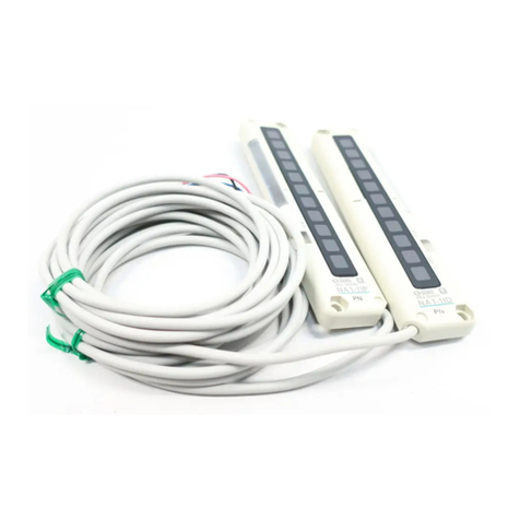
Sunx SF2-A Series User manual

LIGHT CURTAINS
FOR SAFEGUARD
SF4-AH
Light Curtain
SF2-A
SF2-N
SF2-EH
SF-AC
Safety Relay Unit
446
SF2-ASERIES
Small Light Curtain
Bringing world-class
safety standards even
closer to you
Type 2
Standard type
Approved Listing
Conforming to
Machine Directive &
EMC Directive
Self-diagnosis
Diagnosis
Test input
PNP output
type available
High level of safety achieved
Application of IEC 61496 (Type 2) international standard
The SF2-A series conforms to
European and North American safety
standards. So, they can be used in
workplaces throughout the world.
The sensor carries out self-diagnosis when it is turned ON.
The monitoring section (CPU) which is inside the emitter constantly checks the
emitting circuit and the control circuit. Furthermore, the receiver also has a
monitoring section (CPU) which constantly checks the receiving circuit, control
circuit and output circuit, so that a high level of safety is maintained at all times.
Conforming to
Machine Directive &
EMC Directive Approved Listing
CE marking based on Machine Directive
and EMC Directive has been obtained,
so that the sensors can be used in
Control Category 2 equipment.
Type 2 based on IEC 61496-1/2, EN
61496-1 and Control Category 2
based on EN 954-1
C-UL US listings (UL 61496-1/2) which
are required for use in the United States
and Canada have been obtained.
Europe
North
America
Emitter
Receiving circuit
Receiver
Control circuit
Output circuit
Alarm
output OSSD
(control output)
Test input
Monitoring
section (CPU)
Emitting circuit
Alarm output
Control circuit
Monitoring
section (CPU)
Check Check Check
Check
Synchronization line
Emitting
element failure
Emitting
circuit failure
Cable breakage /
short-circuit
Receiving
element failure
Receiving
circuit failure
Output transistor
failure
CPU malfunction
Extraneous light Cable breakage /
short-circuit
Safety design of the SF2-A series
• The sensor switches to the lockout mode when an error occurs, so that the OSSD
(control output) and alarm output turn OFF.
• The output circuit is constantly monitored, so that the sensor also locks out if one of the
transistors is short-circuited.
• Self-diagnosis using test input allows detailed checking such as overlapping emission
(overcurrent error), light emission strength, etc.
Type 2
Stable incident beam indicator
After modifications
Lights up in green
Off
Off Off
Lights up in orange Lights up in orange
Off
When light received is stable
(Amount of light received more than 140 % approx.)
When light received is stable
(Amount of light received 115 to 140 % approx.)
When light received is unstable
(Amount of light received 100 to 115 % approx.)
When light is interrupted
(when OSSD is off) Off
Previous products
We changed unstable incident beam indicator (orange LED) to stable
incident beam indicator (orange / green LED) from the production in June,
2003.
By this change, you can see more stable state of incident beam at a
glance, and you can align beam axis accurately.
[Operation of stable incident beam indicator (EX-unstable incident beam indicator)]
Ramco Innovations - 1207 Maple Street, West Des Moines IA USA 50265 - 800-280-6933 - www.ramcoinnovations.com

LIGHT CURTAINS
FOR SAFEGUARD
SF4-AH
Light Curtain
SF2-A
SF2-NSF2-EHSF-AC
Safety Relay Unit
190 mm
7.480 in
1,950 mm
76.772 in
8 to 96 beam channels
20 mm 0.787 in
beam pitch
4 to 48 beam channels
40 mm 1.575 in
beam pitch
SF2-A
447
Space-saving design only 28 mm 1.102 in
width and 19 mm 0.748 in thickness
With its 28 mm 1.102 in width and
19 mm 0.748 in thickness, it is the
smallest in the world* requiring the
least installation space in the industry.
It can be installed in small spaces
incorporated within equipment.
*Data valid as of June 2002 and based on
research conducted by SUNX.
Different types for different needs
Sensors are available with beam
pitches of 20 mm 0.787 in and 40 mm
1.575 in. The protective height for
sensors ranges from 190 mm 7.480 in
to 1,950 mm 76.772 in, for both 20 mm
0.787 in and 40 mm 1.575 in beam
pitch sensors. NPNPNP output types
are also available for all models. The
sensors can be selected from this wide
variety to suit your requirement.
Thickness
19 mm
0.748 in
Width 28 mm
1.102 in
Operating rangeOperating range
0.3 to 7m0.3 to 7m
0.984 to 22.966 ft0.984 to 22.966 ft
Operating range
0.3 to 7m
0.984 to 22.966 ft
Unaligned beam axes can be seen at a glance
The beam-axis alignment indicators are distributed on the
sensors in four sections. As the indicators of the sections
whose beams are aligned light up in red, the user can easily
verify which beam axes have become aligned. Once all beams
have become aligned, the indicators light up in green. Upon
beginning alignment, as soon as the bottommost or the
topmost beam axis (the standard beam axis) becomes aligned,
the corresponding bottommost or topmost alignment indicator
light begins blinking red. Therefore, beam axes can be easily
aligned by performing the initial beam axis alignment on either
the bottommost or the
topmost beam axis,
then rotating the light
curtain around the axis
of this beam. The
beam-axis alignment
indicators are provided
on both the emitter
and the receiver, so
that you can see at a
glance which beams
are not aligned.
All beam channels are correctly aligned
Beam axes are not correctly aligned
Only the beam axes of the two lower blocks are correctly aligned
All indicators light up in green
Only the bottommost beam axis is correctly aligned
The bottommost indicator blinks red
All indicators light off
The bottom two indicators light up in red
(Beam axes of the two upper blocks are not correctly aligned)
First, ensure that the
bottommost beam
axis is correctly aligned
Rotate the receiver
around the bottommost
beam axis
Blinking
When the upper half of all beam axes are aligned
Conventional unit SF2-A
After all beam channels received
light, the number of indicators that
light up will increase in accordance
with the incident light level
Even though some beam
channels are aligned, the
user cannot determine which
beam channels are aligned
Cannot determine which
beam axes are not aligned
Even though beam channels are
only partially aligned, the user can
determine which beam channels are
aligned (Beam axes of two upper
blocks are aligned / beam axes of
two lower blocks are not aligned)
Upper two indicators: ON
Lower two indicators: OFF
(
(
Ramco Innovations - 1207 Maple Street, West Des Moines IA USA 50265 - 800-280-6933 - www.ramcoinnovations.com

LIGHT CURTAINS
FOR SAFEGUARD
SF4-AH
Light Curtain
SF2-A
SF2-N
SF2-EH
SF-AC
Safety Relay Unit
SF2-A
448
Recognizes extraneous light and prevents malfunctions
Mutual interference is reduced without
the need for interference prevention lines
Spatter protection for the sensing surface
The spatter protection hood type, now available, protects the sensing surface from
welding machine spatter. Moreover, a front protection cover that can be installed
within the sensor casing is also available, completely preventing spatter from
adhering to the sensing surface.
In addition, even though sensed objects may contact the sensor, the sensing
surface will be protected. The ELCA function implements all possible measures to
prevent malfunctions caused by spatter.
Front protection cover protects the sensing surface
In the event that the SF2-A series is
installed in a harsh environment, the
use of the front protection cover
(FC-SF4A-H, optional) will protect
the sensing surface from damage.
Mounting bracket enables easy beam-axis alignment
The beam-axis alignment is easy since
angle adjustment is possible with the
enclosed rear mounting bracket
(MS-SF2N-1).
Alternatively, the side mounting
bracket (MS-SF2N-3) is also available
as an option.
Alignment of beam axes can be accurately performed prior to power-up
By using the SF-LAT-2N laser
alignment tool, you can quickly and
easily align beam axes. The laser
beam spot is easy to see, even when
light curtain units are installed far
apart. In addition, as the SF-LAT-2N
laser alignment tool is battery-
operated, beam axes can be aligned
before powering up the light curtain
itself.
Front protection cover
Rear mounting bracket
1Align the topmost beam axis
Track level
2Align the bottommost beam axis
Reducing mutual
interference
High immunity to
interference from
extraneous light
•
•
••
This function allows the sensor to recognize and reject interference from
instantaneous extraneous light emitted from peripheral equipment, thus
preventing malfunctions caused by a variety of sources, including: other sensor
beams in the vicinity of the operating sensor, beam spatter, AGV and rotating light
sources.
By reducing the number of malfunctions caused by extraneous light, detection
operations will be interrupted less frequently, resulting in substantial improvements
in work efficiency.
The ELCA (Extraneous Light Check &
Avoid) function enhances the mutual
interference prevention function.
ELCA decreases interference from
extraneous light having a similar
frequency as the light used by the
SF2-A series, thereby also minimizing
mutual interference among nearby
SF2-A series sensor units.
Ramco Innovations - 1207 Maple Street, West Des Moines IA USA 50265 - 800-280-6933 - www.ramcoinnovations.com

SF2-A
449
ORDER GUIDE
LIGHT CURTAINS
FOR SAFEGUARD
SF4-AH
Light Curtain
SF2-A
SF2-NSF2-EHSF-AC
Safety Relay Unit
Sensors Mating cable is not supplied with the sensor. Please order it separately.
Note: Refer to ‘TECHNICAL GUIDE’on p.1133 for the definition of the protective height.
Type Appearance Operating range Model No.
NPN output type PNP output type
Number of
beam channels
Protective height
(mm in)
Normal case
20 mm 0.787 in beam pitch40 mm 1.575 in beam pitch20 mm 0.787 in beam pitch40 mm 1.575 in beam pitch
With spatter protection hood
20 mm 0.787 in
25 mm
0.984 in
25 mm
0.984 in
Beam pitch
Protective
height (Note)
Optional mating cable
Beam channel No.
40 mm 1.575 in
45 mm
1.772 in
25 mm
0.984 in
Protective
height (Note)
Beam pitch
Optional mating cable
Beam channel No.
20 mm 0.787 in
25 mm
0.984 in
25 mm
0.984 in
Optional mating cable
Protective
height (Note)
Beam pitch
Beam channel No.
40 mm 1.575 in
45 mm
1.772 in
Optional mating cable
Beam pitch
25 mm
0.984 in
Beam channel No.
Protective
height (Note)
0.5 m
1.640 ft
0.5 m
1.640 ft
0.5 m
1.640 ft
0.5 m
1.640 ft
0.3 to 7 m
0.984 to 22.966 ft
SF2-AH8
SF2-AH12
SF2-AH16
SF2-AH20
SF2-AH24
SF2-AH28
SF2-AH32
SF2-AH36
SF2-AH40
SF2-AH48
SF2-AH56
SF2-AH64
SF2-AH72
SF2-AH80
SF2-AH88
SF2-AH96
SF2-AA4
SF2-AA6
SF2-AA8
SF2-AA10
SF2-AA12
SF2-AA14
SF2-AA16
SF2-AA18
SF2-AA20
SF2-AA24
SF2-AA28
SF2-AA32
SF2-AA36
SF2-AA40
SF2-AA44
SF2-AA48
SF2-AH8-H
SF2-AH12-H
SF2-AH16-H
SF2-AH20-H
SF2-AH24-H
SF2-AH28-H
SF2-AH32-H
SF2-AH36-H
SF2-AH40-H
SF2-AH48-H
SF2-AH56-H
SF2-AH64-H
SF2-AH72-H
SF2-AH80-H
SF2-AH88-H
SF2-AH96-H
SF2-AA4-H
SF2-AA6-H
SF2-AA8-H
SF2-AA10-H
SF2-AA12-H
SF2-AA14-H
SF2-AA16-H
SF2-AA18-H
SF2-AA20-H
SF2-AA24-H
SF2-AA28-H
SF2-AA32-H
SF2-AA36-H
SF2-AA40-H
SF2-AA44-H
SF2-AA48-H
SF2-AH8-PN
SF2-AH12-PN
SF2-AH16-PN
SF2-AH20-PN
SF2-AH24-PN
SF2-AH28-PN
SF2-AH32-PN
SF2-AH36-PN
SF2-AH40-PN
SF2-AH48-PN
SF2-AH56-PN
SF2-AH64-PN
SF2-AH72-PN
SF2-AH80-PN
SF2-AH88-PN
SF2-AH96-PN
SF2-AA4-PN
SF2-AA6-PN
SF2-AA8-PN
SF2-AA10-PN
SF2-AA12-PN
SF2-AA14-PN
SF2-AA16-PN
SF2-AA18-PN
SF2-AA20-PN
SF2-AA24-PN
SF2-AA28-PN
SF2-AA32-PN
SF2-AA36-PN
SF2-AA40-PN
SF2-AA44-PN
SF2-AA48-PN
SF2-AH8-PN-H
SF2-AH12-PN-H
SF2-AH16-PN-H
SF2-AH20-PN-H
SF2-AH24-PN-H
SF2-AH28-PN-H
SF2-AH32-PN-H
SF2-AH36-PN-H
SF2-AH40-PN-H
SF2-AH48-PN-H
SF2-AH56-PN-H
SF2-AH64-PN-H
SF2-AH72-PN-H
SF2-AH80-PN-H
SF2-AH88-PN-H
SF2-AH96-PN-H
SF2-AA4-PN-H
SF2-AA6-PN-H
SF2-AA8-PN-H
SF2-AA10-PN-H
SF2-AA12-PN-H
SF2-AA14-PN-H
SF2-AA16-PN-H
SF2-AA18-PN-H
SF2-AA20-PN-H
SF2-AA24-PN-H
SF2-AA28-PN-H
SF2-AA32-PN-H
SF2-AA36-PN-H
SF2-AA40-PN-H
SF2-AA44-PN-H
SF2-AA48-PN-H
8
12
16
20
24
28
32
36
40
48
56
64
72
80
88
96
4
6
8
10
12
14
16
18
20
24
28
32
36
40
44
48
8
12
16
20
24
28
32
36
40
48
56
64
72
80
88
96
4
6
8
10
12
14
16
18
20
24
28
32
36
40
44
48
190
270
350
430
510
590
670
750
830
990
1,150
1,310
1,470
1,630
1,790
1,950
190
270
350
430
510
590
670
750
830
990
1,150
1,310
1,470
1,630
1,790
1,950
190
270
350
430
510
590
670
750
830
990
1,150
1,310
1,470
1,630
1,790
1,950
190
270
350
430
510
590
670
750
830
990
1,150
1,310
1,470
1,630
1,790
1,950
7.480
10.630
13.780
16.929
20.079
23.228
26.378
29.528
32.677
38.976
45.276
51.575
57.874
64.173
70.472
76.772
7.480
10.630
13.780
16.929
20.079
23.228
26.378
29.528
32.677
38.976
45.276
51.575
57.874
64.173
70.472
76.772
7.480
10.630
13.780
16.929
20.079
23.228
26.378
29.528
32.677
38.976
45.276
51.575
57.874
64.173
70.472
76.772
7.480
10.630
13.780
16.929
20.079
23.228
26.378
29.528
32.677
38.976
45.276
51.575
57.874
64.173
70.472
76.772
0.3 to 7 m
0.984 to 22.966 ft
Ramco Innovations - 1207 Maple Street, West Des Moines IA USA 50265 - 800-280-6933 - www.ramcoinnovations.com

SF2-A
450
ORDER GUIDE
LIGHT CURTAINS
FOR SAFEGUARD
SF4-AH
Light Curtain
SF2-A
SF2-N
SF2-EH
SF-AC
Safety Relay Unit
Mating cable is not supplied with the sensor. Please order it separately.
Mating cables
AppearanceDesignation DescriptionModel No.
Cable with
connector on
one end
Cable with
connector on
both ends
SF2N-CC3
SF2N-CC7
SF2N-CC10
SF2N-CCJ10
Length: 3 m 9.843 ft
Weight: 400 g approx.
(two cables)
Length: 7 m 22.966 ft
Weight: 870 g approx.
(two cables)
Length: 10 m 32.808 ft
Weight: 1,200 g approx.
(two cables)
Length: 10 m 32.808 ft
Weight: 1,200 g approx.
(two cables)
These cables are used for wiring.
7-core (6-core for emitter) shielded cable with connector on
one end, two cables per set
Cable outer diameter:"6 mm "0.236 in
Connector outer diameter:"14 mm "0.551 in max.
Cable color:Gray (for emitter)
Gray with black line (for receiver)
This cable is used for cable extension.
Shielded cable with connector on both ends, two cables per set
Cable outer diameter:"6 mm "0.236 in
Connector outer diameter:"14 mm "0.551 in max.
Cable color:Gray (for emitter), Gray with black line (for receiver)
Spare parts (Accessories for sensor) Rear mounting
bracket
•MS-SF2N-1
U-shaped rear mounting intermediate
supporting bracket
L-shaped intermediate supporting bracket
•MS-SF2N-2
•MS-SF4A-H2
•MS-SF2N-L
Designation DescriptionModel No.
MS-SF2N-1 Used to mount the sensor on the rear surface
(1 set for emitter and receiver)
Used for standard sensing to detect the smallest objects
("30 mm "1.181 in), with 20 mm 0.787 in beam pitch
Rear mounting bracket
Test rod
U-shaped rear mounting
intermediate supporting
bracket (Note)
MS-SF2N-2
MS-SF4A-H2
ForSF2-A□(-PN)
L-shaped intermediate
supporting bracket (Note) MS-SF2N-L
SF2-AH-TR
Used to hold the sensor at the intermediate
position for protection against vibration (for rear
surface mounting) (1 set for emitter and receiver)
ForSF2-A□(-PN)-H
Used to install the intermediate supporting bracket
on the wall side, etc. (1 set for emitter and receiver)
Note: The number of sets required varies depending on the product. Refer to ‘DIMENSIONS’on
p.461 for further details.
OPTIONS
Designation
Applicable
beam
channels
8 beam
channels 12 beam
channels 16 beam
channels 20 beam
channels 24 beam
channels 28 beam
channels 32 beam
channels 36 beam
channels 40 beam
channels 48 beam
channels 56 beam
channels 64 beam
channels 72 beam
channels 80 beam
channels 88 beam
channels 96 beam
channels
4 beam
channels
20 mm
0.787 in
beam pitch
40 mm
1.575 in
beam pitch
6 beam
channels 8 beam
channels 10 beam
channels 12 beam
channels 14 beam
channels 16 beam
channels 18 beam
channels 20 beam
channels 24 beam
channels 28 beam
channels 32 beam
channels 36 beam
channels 40 beam
channels 44 beam
channels 48 beam
channels
OS-SF4A-H8
OS-SF4A-H12 OS-SF4A-H16 OS-SF4A-H20 OS-SF4A-H24 OS-SF4A-H28 OS-SF4A-H32 OS-SF4A-H36 OS-SF4A-H40 OS-SF4A-H48 OS-SF4A-H56 OS-SF4A-H64 OS-SF4A-H72 OS-SF4A-H80
FC-SF4A-H8
FC-SF4A-H12 FC-SF4A-H16 FC-SF4A-H20 FC-SF4A-H24 FC-SF4A-H28 FC-SF4A-H32 FC-SF4A-H36 FC-SF4A-H40 FC-SF4A-H48 FC-SF4A-H56 FC-SF4A-H64 FC-SF4A-H72 FC-SF4A-H80
OS-SF4A-H88
FC-SF4A-H88
OS-SF4A-H96
FC-SF4A-H96
Model No.
Model No.
FC-SF4A-H8-H
FC-SF4A-H12-H FC-SF4A-H16-H FC-SF4A-H20-H FC-SF4A-H24-H FC-SF4A-H28-H FC-SF4A-H32-H FC-SF4A-H36-H FC-SF4A-H40-H FC-SF4A-H48-H FC-SF4A-H56-H FC-SF4A-H64-H FC-SF4A-H72-H FC-SF4A-H80-H FC-SF4A-H88-H FC-SF4A-H96-H
Model No.
OS-SF4A-H8-H
OS-SF4A-H12-H OS-SF4A-H16-H OS-SF4A-H20-H OS-SF4A-H24-H OS-SF4A-H28-H OS-SF4A-H32-H OS-SF4A-H36-H OS-SF4A-H40-H OS-SF4A-H48-H OS-SF4A-H56-H OS-SF4A-H64-H OS-SF4A-H72-H OS-SF4A-H80-H OS-SF4A-H88-H OS-SF4A-H96-H
Model No.
For
SF2-A□(-PN)
For
SF2-A□(-PN)-H
For
SF2-A□(-PN)
For
SF2-A□(-PN)-H
Front protection cover
Slit mask
Sensing
surface
Sensor
U-shaped
rear mounting
intermediate
supporting bracket
MS-SF2N-2 /
MS-SF4A-H2
(Note)
L-shaped intermediate
supporting bracket
MS-SF2N-L
Eight M3 (length 5 mm
0.197 in) hexagon-
socket-head bolts are
attached.
Four bracket set
Note:
The above figure is only ap-
plicable to the MS-SF2N-2. The
MS-SF4A-H2 has a different shape.
•MS-SF2N-2 / MS-SF4A-H2
•
Set of 2 pcs. each of U-shaped rear
supporting bracket and retaining plate
•MS-SF2N-L
•Two L-shaped bracket set
Two M3 (length 10 mm 0.394 in) pan
head screws, two M4 (length 10 mm
0.394 in) hexagon-socket-head bolts
and two nuts are attached.
Slit mask
Slit mask
•FC-SF4A-H
Front protection
cover
It protects the
sensing surface
Front protection
cover
•FC-SF4A-H-H •OS-SF4A-H•OS-SF4A-H-H
The slit mask restrains the amount of beam emitted or
received and hence reduces the interference between
neighboring sensors.
It is also used in cases when the beam intensity is too strong
penetrating through the sensing object.
However, the operating range reduces when the slit mask is
used.
<OS-SF4A-H/ OS-SF4A-H-H>
•Slit on the emitter side: 2.6 m 8.530 ft
•Slit on the receiver side: 2.6 m 8.530 ft
•Slit on both sides: 1.2 m 3.937 ft
Operating range
Note: The model Nos. given above denote a single unit, not a pair of units. 2 pcs. (2 sets) are required to mount the emitter / receiver.
Front protection cover Slit mask
Ramco Innovations - 1207 Maple Street, West Des Moines IA USA 50265 - 800-280-6933 - www.ramcoinnovations.com

SF2-A
451
OPTIONS
LIGHT CURTAINS
FOR SAFEGUARD
SF4-AH
Light Curtain
SF2-A
SF2-NSF2-EHSF-AC
Safety Relay Unit
With the large display unit put on the light curtain, the
operation is easily observable from various directions.
Specifications
I/O circuit diagrams
•Supply voltage: 24 V DC15 %
•Current consumption: 12 mA or less
•Indicators: Orange LED (8 pcs.used)
[Light up when external contact is ON]
•
Ambient temperature: 10 to55 C 14 to131 F
(No dew condensation or icing allowed)
•Material: POM (Case)
Polycarbonate (Cover)
Cold rolled carbon steel (SPCC)(Bracket)
•
Cable:
0.3 mm
2
2-core cabtyre cable, 3 m 9.843 ft long
•Weight: 70 g approx. (including bracket)
Color code
Color codeColor code
<
With NPN output type
>
24 V DC
15 %
(Brown) V
(Blue)V
Internal circuit
or
or
Non-voltage contact or NPN open-collector
transistor
Users’circuit
<
With PNP output type
>
24 V DC
15 %
(Brown) V
(Blue) V
Internal circuit
Non-voltage contact or PNP open-collector
transistor
Users’circuit
m
1
m
1
m
1
m
1
Used for side-mounting of sensors
(four bracket set for emitter and receiver)
Used to hold the sensor at the
intermediate position for protection
against vibration (for side mounting)
(1 set for emitter and receiver)
Used for one-point rear mounting
Convenient for mounting on an aluminum frame
(four bracket set for emitter and receiver)
Used for standard sensing to detect the smallest objects
("50 mm "1.969 in), with 40 mm 1.575 in beam pitch
Relay unit for PNP output type
•Complies with Control Categories
up to 4 based on EN 954-1
Categories up to 2 when it is
combines with the SF2-A series
Easy to align the beam axis with the visible laser beam
Designation Model No. Description
Side mounting bracket
U-shaped side mounting
intermediate supporting
bracket (Note 1)
Center sensor mounting
bracket (Note 2)
Test rod
Safety relay unit
For PNP output
type light curtain
(Note 3)
Laser alignment tool
(Note 4)
MS-SF2N-3
MS-SF2N-4
MS-SF4A-H4
For SF2-A(-PN)
For SF2-A
(-PN)-H
Enabling path3
SF-LAT-2N
MS-SF2N-5
SF2-AA-TR
SF-AC
Large display unit
for light curtain SF-IND-2
Notes:1)The number of sets required varies depending on the product. Refer to
‘DIMENSIONS’on p.462 for further details.
Notes: 2)Multiple beam channel sensors requiring the intermediate supporting bracket
(20 mm 0.787 in beam pitch type: 36 beam channels or more, 40 mm 1.575 in
beam pitch type: 18 beam channels or more) cannot be mounted on an aluminum
frame with the center sensor mounting bracket.
Notes: 3) Refer to p.500lfor further details about the SF-AC.
Notes: 4)
Refer to ‘SF4-AH’ series on p.420lfor further details about the laser alignment tool.
()
Attaches to upper edge of
light curtain.
Tighten together the mounting
bracket provided with the area
sensor and the mounting
bracket of SF-IND-2.
Large display unit
for light curtain Side mounting
bracket
Hexagon-socket-
head bolt
M5 (length 10 mm
0.394 in or more)
(Please arrange separately.)
Hexagon-socket-
head bolt
Accessory for
MS-SF2N-1
Four bracket set
()
()
Safety relay unit
For PNP output type
light curtain
•SF-AC
Laser alignment tool
U-shaped side
mounting intermediate
supporting bracket
Center sensor
mounting bracket
Hexagon-socket-
head bolt
Accessory for
MS-SF2N-1
Four bracket set
L-shaped intermediate
supporting bracket
MS-SF2N-L
(Accessory for sensor)
Sensing
surface
Sensor
U-shaped side
mounting intermediate
supporting bracket
MS-SF2N-4
/
MS-SF4A-H4
(Note)
•SF-LAT-2N
•MS-SF2N-5 •MS-SF2N-4
•MS-SF4A-H4
•MS-SF2N-3•SF-IND-2
(
(
Note:The above figure is
only applicable to the
MS-SF2N-4.
The MS-SF4A-H4 has
a different shape.
•MS-SF2N-4 /MS-SF4A-H4
Set of 2 pcs. each of U-shaped
side supporting bracket and
retaining plate
•MS-SF2N-L
(Accessory for sensor)
Two L-shaped bracket set
Two M3 (length 10 mm
0.394 in) pan head screws,
two M4 (length 10 mm
0.394 in) hexagon-socket-
head bolts and two nuts are
attached.
(
(
Ramco Innovations - 1207 Maple Street, West Des Moines IA USA 50265 - 800-280-6933 - www.ramcoinnovations.com

SF2-A
452
SPECIFICATIONS
LIGHT CURTAINS
FOR SAFEGUARD
SF4-AH
Light Curtain
SF2-A
SF2-N
SF2-EH
SF-AC
Safety Relay Unit
Individual specifications
SF2-AH(-H)
SF2-AA(-H)
Item
No. of beam channels
Beam pitch
SF2-AH
(
-PN
)
-H
SF2-AH
(
-PN
)
NPN output
PNP output
Type
Current consumption
Protective height
Model
No.
Weight
Total of emitter
and receiver
(
(
8
20 mm 0.787 in beam pitch
SF2-AH8
(
-H
)
SF2-AH8-PN
(
-H
)
12
SF2-AH12
(
-H
)
SF2-AH12-PN
(
-H
)
16
SF2-AH16
(
-H
)
SF2-AH16-PN
(
-H
)
20
SF2-AH20
(
-H
)
SF2-AH20-PN
(
-H
)
24
SF2-AH24
(
-H
)
SF2-AH24-PN
(
-H
)
28
SF2-AH28
(
-H
)
SF2-AH28-PN
(
-H
)
32
SF2-AH32
(
-H
)
SF2-AH32-PN
(
-H
)
350 g approx. 430 g approx. 520 g approx. 610 g approx. 700 g approx. 780 g approx. 880 g approx. 960 g approx.
420 g approx. 560 g approx. 700 g approx. 830 g approx. 970 g approx. 1,100 g approx.1,200 g approx.1,400 g approx.
190 mm 7.480 in
270 mm 10.630 in
350 mm 13.780 in
430 mm 16.929 in
510 mm 20.079 in
20 mm 0.787 in
590 mm 23.228 in 670 mm 26.378 in 750 mm 29.528 in
Emitter: 45 mA or less, Receiver: 60 mA or less Emitter: 55 mA or less, Receiver: 70 mA or less
Item
Type 20 mm 0.787 in beam pitch
SF2-AH48
(
-H
)
SF2-AH48-PN
(
-H
)
SF2-AH40
(
-H
)
SF2-AH40-PN
(
-H
)
SF2-AH56
(
-H
)
SF2-AH56-PN
(
-H
)
SF2-AH64
(
-H
)
SF2-AH64-PN
(
-H
)
SF2-AH72
(
-H
)
SF2-AH72-PN
(
-H
)
SF2-AH80
(
-H
)
SF2-AH80-PN
(
-H
)
SF2-AH88
(
-H
)
SF2-AH88-PN
(
-H
)
SF2-AH96
(
-H
)
SF2-AH96-PN
(
-H
)
NPN output
PNP output
Model
No.
36
SF2-AH36
(
-H
)
SF2-AH36-PN
(
-H
)
20 mm 0.787 in
40 48 56 64 72 80 88 96
830 mm 32.677 in 990 mm 38.976 in
1,150 mm 45.276 in 1,310 mm 51.575 in 1,470 mm 57.874 in 1,630 mm 64.173 in 1,790 mm 70.472 in 1,950 mm 76.772 in
1,100 g approx. 1,200 g approx. 1,400 g approx. 1,600 g approx. 1,800 g approx. 1,900 g approx. 2,100 g approx. 2,300 g approx.
1,500 g approx. 1,800 g approx. 2,100 g approx. 2,300 g approx. 2,600 g approx. 2,900 g approx. 3,200 g approx. 3,400 g approx.
Emitter: 60 mA or less, Receiver: 80 mA or less Emitter: 65 mA or less, Receiver: 95 mA or less Emitter: 70 mA or less, Receiver: 110 mA or less Emitter:80 mA or less, Receiver: 120 mA or less
SF2-AH
(
-PN
)
-H
SF2-AH
(
-PN
)
No. of beam channels
Beam pitch
Current consumption
Protective height
Weight
Total of emitter
and receiver
(
(
SF2-AA
(
-PN
)
-H
SF2-AA
(
-PN
)
SF2-AA
(
-PN
)
-H
SF2-AA
(
-PN
)
Item
Type
No. of beam channels
Beam pitch
NPN output
PNP output
Current consumption
Protective height
Model
No.
Item
Type
No. of beam channels
Beam pitch
NPN output
PNP output
Current consumption
Protective height
Model
No.
Weight
Total of emitter
and receiver
(
(
Weight
Total of emitter
and receiver
(
(
4
40 mm 1.575 in beam pitch
SF2-AA4
(
-H
)
SF2-AA4-PN
(
-H
)
6
SF2-AA6
(
-H
)
SF2-AA6-PN
(
-H
)
8
SF2-AA8
(
-H
)
SF2-AA8-PN
(
-H
)
10
SF2-AA10
(
-H
)
SF2-AA10-PN
(
-H
)
12
SF2-AA12
(
-H
)
SF2-AA12-PN
(
-H
)
14
SF2-AA14
(
-H
)
SF2-AA14-PN
(
-H
)
16
SF2-AA16
(
-H
)
SF2-AA16-PN
(
-H
)
18
SF2-AA18
(
-H
)
SF2-AA18-PN
(
-H
)
40 mm 1.575 in
Emitter: 40 mA or less, Receiver: 50 mA or less Emitter: 45 mA or less, Receiver: 60 mA or less
190 mm 7.480 in
270 mm 10.630 in 350 mm 13.780 in
430 mm 16.929 in
510 mm 20.079 in 590 mm 23.228 in 670 mm 26.378 in 750 mm 29.528 in
350 g approx. 430 g approx. 520 g approx. 610 g approx. 700 g approx. 780 g approx. 880 g approx. 960 g approx.
420 g approx. 560 g approx. 700 g approx. 830 g approx. 970 g approx. 1,100 g approx.1,200 g approx.1,400 g approx.
40 mm 1.575 in
20
40 mm 1.575 in beam pitch
24
SF2-AA24
(
-H
)
SF2-AA24-PN
(
-H
)
SF2-AA20
(
-H
)
SF2-AA20-PN
(
-H
)
28
SF2-AA28
(
-H
)
SF2-AA28-PN
(
-H
)
32
SF2-AA32
(
-H
)
SF2-AA32-PN
(
-H
)
36
SF2-AA36
(
-H
)
SF2-AA36-PN
(
-H
)
40
SF2-AA40
(
-H
)
SF2-AA40-PN
(
-H
)
44
SF2-AA44
(
-H
)
SF2-AA44-PN
(
-H
)
48
SF2-AA48
(
-H
)
SF2-AA48-PN
(
-H
)
Emitter: 50 mA or less, Receiver: 65 mA or less Emitter: 50 mA or less, Receiver:70 mA or less Emitter: 55 mA or less, Receiver: 75 mA or less Emitter: 60 mA or less, Receiver: 80 mA or less
830 mm 32.677 in 990 mm 38.976 in
1,150 mm 45.276 in 1,310 mm 51.575 in 1,470 mm 57.874 in 1,630 mm 64.173 in 1,790 mm 70.472 in 1,950 mm 76.772 in
1,100 g approx. 1,200 g approx. 1,400 g approx. 1,600 g approx. 1,800 g approx. 1,900 g approx. 2,100 g approx. 2,300 g approx.
1,500 g approx. 1,800 g approx. 2,100 g approx. 2,300 g approx. 2,600 g approx. 2,900 g approx. 3,200 g approx. 3,400 g approx.
Ramco Innovations - 1207 Maple Street, West Des Moines IA USA 50265 - 800-280-6933 - www.ramcoinnovations.com

SF2-A
453
SPECIFICATIONS
LIGHT CURTAINS
FOR SAFEGUARD
SF4-AH
Light Curtain
SF2-A
SF2-NSF2-EHSF-AC
Safety Relay Unit
Common specifications
Notes: 1) Since the color of operation indicator changes according to the ON / OFF state of control output (OSSD), the operation indicator is marked as ‘OSSD’
on the sensor.
Notes: 2) Surge absorber is connected between the main body enclosure and the supply terminals to avoid faulty operation due to surge. For this reason, the
values for dielectric strength voltage and insulation resistance are given for the condition when the surge absorber has been removed.
Notes: 3) U-shaped rear mounting intermediate supporting bracket (MS-SF2N-2 or MS-SF4A-H2) and L-shaped intermediate supporting bracket (MS-SF2N-L)
are attached with the following sensors. The number of attached U-shaped rear mounting intermediate supporting bracket and L-shaped intermediate
supporting bracket are different depending on the sensor as follows.
SF2-AH36(-PN)(-H), SF2-AH40(-PN)(-H), SF2-AA18(-PN)(-H), SF2-AA20(-PN)(-H): 1 set
SF2-AH48(-PN)(-H), SF2-AA24(-PN)(-H): 2 sets
SF2-AH56(-PN)(-H), SF2-AH64(-PN)(-H), SF2-AH72(-PN)(-H), SF2-AA28(-PN)(-H), SF2-AA32(-PN)(-H), SF2-AA36(-PN)(-H): 3 sets
SF2-AH80(-PN)(-H), SF2-AA40(-PN)(-H): 4 sets
SF2-AH88(-PN)(-H), SF2-AH96(-PN)(-H), SF2-AA44(-PN)(-H), SF2-AA48(-PN)(-H): 5 sets
Category 2 based on EN 954-1 (Type 2 based on IEC 61496-1/2)
0.3 to 7 m 0.984 to 22.966 ft
"30 mm "1.181 in opaque object
5 °or less for a operating range exceeding 3 m 9.843 ft (conforming to IEC 61496-2 / UL 61496-2)
24 V DC15 % Ripple P-P 10 % or less
<NPN output type>
NPN open-collector transistor
•Maximum sink current: 200 mA
•
Applied voltage: Same as supply voltage (between control output and 0 V)
•Residual voltage: 2.0 V or less (at 200 mA sink current)
DC-12 or DC-13
ON when all beam channels are received, OFF when one or more beam channels are interrupted
(OFF also in case of any malfunction in the sensor or the synchronization signal)
Incorporated
OFF response: 15 ms or less, ON response: 40 to 60 ms or less (under stable light received condition)
<NPN output type>
NPN open-collector transistor
•Maximum sink current: 60 mA
•
Applied voltage: Same as supply voltage (between alarm output and 0 V)
•Residual voltage: 2.0 V or less (at 60 mA sink current)
Normal operation: Alarm output ON, Failure resulting in emission halt, or when test input is applied: Alarm output OFF
Incorporated
Beam-axis alignment indicators: 2-color (Red / Green) LED4 (lights up in red when the each beam channel receives light,
blinks in red when the topmost or bottommost beam channel receives light, light up in green when all beam channels receive light)
Operation indicator (Note 1): 2-color (Red / Green) LED [lights up in red when control output (OSSD) is OFF, lights up in green
when control output (OSSD) is ON]
Emission halt indicator: Orange LED (lights up when emission halts)
Fault indicator: Yellow LED (lights up or blinks if a fault occurs in the sensor)
Beam-axis alignment indicators: 2-color (Red / Green) LED4 (lights up in red when the each beam channel receives light,
blinks in red when the topmost or bottommost beam channel receives light, light up in green when all beam channels receive light)
OSSD indicator: 2-color (Red / Green) LED [lights up in red when control output (OSSD) is OFF, light up in green when control
output (OSSD) is ON]
Unstable incident beam indicator: Orange LED (lights up when light received is unstable)
Fault indicator: Yellow LED (lights up or blinks if a fault occurs in the sensor)
Incorporated
3 (Industrial environment)
IP65 (IEC)
10 to55 C 14 to131 F(No dew condensation or icing allowed), Storage: 25 to70 C 13 to158 F/
30 to 85 % RH, Storage: 30 to 95 % RH
Sunlight: 20,000 ?x at the light-receiving face, Incandescent light: 3,500 ?x at the light-receiving face
1,000 V AC for one min. between all supply terminals connected together and enclosure (Note 2) /
20 MΩ, or more, with 500 V DC megger between all supply terminals connected together and enclosure (Note 2)
10 to 55 Hz frequency, 0.75 mm 0.030 in amplitude in X, Y and Z directions for two hours each /
300 m/s2acceleration (30 G approx.) in X, Y and Z directions for three times each
Infrared LED (Peak emission wavelength: 870 nm 0.034 mil)
Enclosure: Aluminium, Resin case: ABS, Lens: Polycarbonate, Cap: PBT
Emitter: 6-core (0.3 mm24-core, 0.2 mm22-core) shielded cable, 0.5 m 1.640 ft long, with a connector at the end
Receiver: 7-core (0.3 mm25-core, 0.2 mm22-core) shielded cable, 0.5 m 1.640 ft long, with a connector at the end
Extension up to total 20.5 m 67.257 ft is possible, for both emitter and receiver, with optional mating cables
MS-SF2N-1 (Rear mounting bracket): 1 set for emitter and receiver
MS-SF2N-2 (U-shaped rear mounting intermediate supporting bracket, MS-SF4A-H2 for ‘-H’type): (Note 3)
MS-SF2N-L (L-shaped intermediate supporting bracket): (Note 3)
SF2-AH-TR (Test rod): 1 pc. [SF2-AH(-PN)(-H) only]
<PNP output type>
PNP open-collector transistor
•Maximum source current: 200 mA
•
Applied voltage:
Same as supply voltage (between control output and
V)
•
Residual voltage: 2.5 V or less (at 200 mA source current)
<PNP output type>
PNP open-collector transistor
•Maximum source current: 60 mA
•
Applied voltage: Same as supply voltage (between alarm output and
V)
•Residual voltage: 2.5 V or less (at 60 mA source current)
20 mm 0.787 in beam pitch 40 mm 1.575 in beam pitch
NPN output PNP output NPN output PNP output
SF2-AH(-H)SF2-AH-PN(-H)SF2-AA(-H)SF2-AA-PN(-H)
Type
Model No.Item
Applicable standards
Operating range
Detection capability
Effective aperture angle
Supply voltage
Control output (OSSD)
Response time
Alarm output
Emitter
Receiver
Test input (emission halt) function
Pollution degree
Degree of protection
Ambient temperature /
Ambient humidity
Ambient illuminance
Dielectric strength voltage /
Insulation resistance
Vibration resistance /
Shock resistance
Emitting element
Material
Cable
Cable extension
Accessories
Utilization category
Operation mode
Protection circuit
Operation mode
Protection circuit
Indicators
"50 mm "1.969 in opaque object
Environmental resistance
Ramco Innovations - 1207 Maple Street, West Des Moines IA USA 50265 - 800-280-6933 - www.ramcoinnovations.com

LIGHT CURTAINS
FOR SAFEGUARD
SF4-AH
Light Curtain
SF2-A
SF2-N
SF2-EH
SF-AC
Safety Relay Unit
SF2-A
454
I/O CIRCUIT AND WIRING DIAGRAMS
NPN output type
I/O circuit diagram Wiring diagram
2
5
6
6
5
4
1
2
7
4
7
3
or
3
Sensor circuit
m1
Load
Emitter Connector pin No.
Color code of mating cable
Sensor circuit
60 mA max.
(Brown)V
(Pink) Alarm output
(Blue) 0 V
(Gray) Not connected
(Orange) Synchronization
(Orange / Black) Synchronization
Users’circuitInternal circuit
200 mA max.
(Brown)V
(Black) OSSD
(Gray) Test input (emission halt input)
(Orange) Synchronization
(Violet) Not connected
(Orange / Black)
Synchronization
(Blue) 0 V
Receiver
24 V DC
15 %
FSD
Note: Unused wires must be insulated to ensure that they do not come into
contact with wires already in use.
Non-voltage contact or NPN open-collector transistor
•Test input (emission halt input)
0 to15 V: Emission (source current: 2 mA or less)
Open, or Vs1.5 V to Vs: Emission halt
(Note)
Users’circuitInternal circuit
Note:Vs is the same voltage as the voltage of the power supply to be used.
m1
CAUTION
Use a safety relay unit or an equivalent safety control circuit for FSD.
F.G.
4Not connected
Emitter
1No use
70 V
2V
6
Synchronization
5
Synchronization
3Alarm output
8Shield
(Note 3)
Connector pin No.
Color code of mating cable
Load
Brown
Pink
Blue
Gray (Not connected)
Orange
Orange / Black
24 V DC
15 %
Shield
(Note 3)
2V
Receiver
8Shield (Note 3)
1Not connected
70 V
3
OSSD
6Synchronization
5Synchronization
4
Test input
(emission halt input)
F.G.
Shield
(Note 3)
FSD
Orange / Black
Orange
Gray
Violet
(Not connected)
Brown
Black
Blue
m1
Unused wires must be insulated to ensure that they do not come
into contact with wires already in use.
Conductor cross-section area of lead wire of mating cable is 0.2 mm2
(synchronization wire) and 0.3 mm2(exclude synchronization wire).
Be sure to connect the shield wire to the frame ground (F.G.).
Notes: 1)
2)
3)
Ramco Innovations - 1207 Maple Street, West Des Moines IA USA 50265 - 800-280-6933 - www.ramcoinnovations.com

SF2-A
455
I/O CIRCUIT AND WIRING DIAGRAMS
LIGHT CURTAINS
FOR SAFEGUARD
SF4-AH
Light Curtain
SF2-A
SF2-NSF2-EHSF-AC
Safety Relay Unit
PNP output type
I/O circuit diagram Wiring diagram
2
5
6
FSD
6
5
2
7
4
7
3
4
1
3
Load
Emitter
Receiver
Sensor circuitSensor circuit
Connector pin No.
Color code of mating cable
60 mA max.
(Brown)V
(Pink) Alarm output
(Blue) 0 V
(Gray) Not connected
(Orange) Synchronization
(Orange / Black) Synchronization
Users’circuitInternal circuit
200 mA max.
(Brown)V
(Gray) Test input (emission halt input)
(Orange) Synchronization
(Violet) Not connected
(Orange / Black)
Synchronization
24 V DC
15 %
(Black) OSSD
(Blue) 0 V
Users’circuitInternal circuit
m1
Note: Unused wires must be insulated to ensure that they do not come into
contact with wires already in use.
m1
Non-voltage contact or PNP open-collector transistor
or
•Test input (emission halt input)
9 V to Vs: Emission (sink current: 2 mA or less)
Open, or 0 to1.5 V: Emission halt
(Note)
Note:Vs is the same voltage as the voltage of the power supply to be used.
CAUTION
Use a safety relay unit or an equivalent safety control circuit for FSD.
Emitter
Receiver
4
Not connected
1No use
70 V
2V6
Synchronization
5
Synchronization
3Alarm output
8Shield
(Note 3)
Connector pin No.
Color code of mating cable
F.G.
Load
Brown
Pink
Blue
Gray (Not connected)
Orange
Orange / Black
24 V DC
15 %
Shield
(Note 3)
2V8Shield (Note 3)
1Not connected
70 V
3
OSSD
6Synchronization
5Synchronization
4
Test input
(emission halt input)
Unused wires must be insulated to ensure that they do not come
into contact with wires already in use.
Conductor cross-section area of lead wire of mating cable is 0.2 mm2
(synchronization wire) and 0.3 mm2(exclude synchronization wire).
Be sure to connect the shield wire to the frame ground (F.G.).
Notes: 1)
2)
3)
F.G.
Shield
(Note 3) FSD
Orange / Black
Orange
Gray
Violet
(Not connected)
Brown
Black
Blue
m1
Test input (Gray)
OSSD
(Black)
TEST
RESET
(Note 3)
mE: Emitter
R: Receiver
Shield
Shield
Emitter
Receiver
Alarm output (Pink)
V (Brown)
0 V (Blue)
0 V (Blue)
V (Brown)
Sync.
(Orange / Black)
Sync.(Orange)
Synchronization(Orange / Black)
Synchronization(Orange)
24 V DC
10 %
Not connected (Gray) Not connected (Violet) L1
NM
Fuse 1 Fuse 2
R
V
S2
X12
X11
S1
X3
X2
X1A1 3323 411351
A_IN
T_IN
K2
KA KA
KB
K2K1
K3
K1
K3
1452
R
Sy
E
Sy
24 34
42
L1L2L3
3
KB
A2 E
0 V R
0 V
K4
R
Sy
E
Sy
E
(F.G.) R(F.G.)
E
V
F1
Power Ui
NPN
PNP
PE
(Note 1)
SF-AC
CONTROL-LOGIC
KA, KB: Magnet contactor
Test input polarity selection switch
Notes: 1) Connect the light curtain’s shield wire to the frame ground (F.G.), and ground the SF-AC’s PE terminal.
Notes: 2) If using the equipment with the manual reset, wire X1 to X2 as per the illustration above.
If using with the automatic reset, disconnect X2 wire and connect it to X3. In this case, reset button is not required.
Notes: 3) Use a momentary-type switch for the reset button.
Set the test input polarity
selection switch of SF-AC
to the ‘PNP’side.
A1
FG
Sy+
Sy-
T-IN
A-IN
+V
0V 52
42
X12
34
X11
24 PE
14
FG
A2
Sy-
Sy+
S2
S1
Receiver
0V
+V41
51 33
X2 23
X1 13
X3
Power Test
Ui
K1
K2
SF-AC
SF-AC Terminal
arrangement diagram
SF-AC Wiring diagram (Control category 2)
Ramco Innovations - 1207 Maple Street, West Des Moines IA USA 50265 - 800-280-6933 - www.ramcoinnovations.com

SF2-A
456
PRECAUTIONS FOR PROPER USE
LIGHT CURTAINS
FOR SAFEGUARD
SF4-AH
Light Curtain
SF2-A
SF2-N
SF2-EH
SF-AC
Safety Relay Unit
Part description and function
1
2
3
4
Notes: 1) Since the color of the operation indicator changes according to the ON / OFF state of ‘OSSD’, the
operation indicator is marked as OSSD on the sensor.
Notes: 2) The blinking cycle of the fault indicator is illustrated below.The number of blinks indicate what kind of
fault has occurred. There is an interval of approx. 1 sec. between blinking.
Wiring
Refer to the applicable regulations for the region where
this device is to be used when setting up the device. In
addition, make sure that all necessary measures are
taken to prevent possible dangerous operating errors
resulting from earth faults.
•Do not utilize this sensor in ‘PSDI Mode’, in which the
sensor is utilized as an activator for machinery.
•To use this product in the U.S.A., refer to OSHA 1910.
212 and OSHA 1910. 217 for installation, and in
Europe, refer to EN 999 as well. Observe your national
and local requirements before installing this product.
•This sensor is a Type 2 electro-sensitive protective
equipment. It is specified that this sensor be utilized
only within systems implementing safety categories 2,
1 and B (safety-related categories for control systems),
as determined by European Standard EN 954-1. This
sensor must never be utilized in any system that
requires the usage of category 4 equipment, such as
press machines; nor for systems requiring category 3
equipment.
• This catalog is a guide to select a suitable product. Be sure to
read the instruction manual attached to the product prior to its
use.
•Make sure to carry out the test run before regular operation.
•This safety system is for use only on machinery in which the
dangerous parts can be stopped immediately, either by an
emergency stop unit or by disconnecting the power supply. Do not
use this system with machinery which cannot be stopped at any
point in its operation cycle.
•Make sure that the power supply is off while wiring.
•Verify that the supply voltage variation is within the rating.
•If power is supplied from a commercial switching regulator,
ensure that the frame ground (F.G.) terminal of the power supply
is connected to an actual ground.
•In case noise generating equipment (switching regulator, inverter
motor, etc.) is used in the vicinity of this sensor, connect the frame
ground (F.G.) terminal of the equipment to an actual ground.
•
Do not run the wires together with high-voltage lines or power lines
or put them in the same raceway.This can cause malfunction due
to induction.
Others
•Do not use during the initial transient time (2 sec.) after the power
supply is switched on.
•Avoid dust, dirt and steam.
•Take care that the sensor does not come in direct contact with
water, oil, grease, or organic solvents, such as, thinner, etc.
•Take care that the sensor is not directly exposed to fluorescent
light from a rapid-starter lamp or a high frequency lighting device,
as it may affect the sensing performance.
Blinking cycle of fault indicator
0.3
sec. 0.3
sec. 1 sec.
OFF
ON
No.of blinks
No.of blinks
Top:
Blinks in red when the topmost beam channel receives light, lights up in red when sensor top receives light.
Upper middle: Lights up in red when sensor upper middle receives light.
Lower middle: Lights up in red when sensor lower middle receives light.
Bottom:
Blinks in red when the bottommost beam channel receives light, lights up in red when sensor bottom receives light.
Lights up in green when all beam channels (top, upper middle, lower middle and bottom) receive light.
Lights up in red when control output (OSSD) is OFF, lights up in green
when control output (OSSD) is ON.
Lights up when emission halts.
Lights up or blinks when a fault occurs in the sensor. (Note 2)
Lights up: Malfunction of internal circuit
Blinks: Effects from noise, power supply or malfunction of internal circuit
Top:
Blinks in red when the topmost beam channel receives light, lights up in red when sensor top receives light.
Upper middle: Lights up in red when sensor upper middle receives light.
Lower middle: Lights up in red when sensor lower middle receives light.
Bottom:
Blinks in red when the bottommost beam channel receives light, lights up in red when sensor bottom receives light.
Lights up in green when all beam channels (top, upper middle, lower middle and bottom) receive light.
Lights up in red when control output (OSSD) is OFF, lights up in green
when control output (OSSD) is ON.
Lights up when light received is unstable.
Lights up or blinks when a fault occurs in the sensor. (Note 2)
Lights up: Fault occurs in OSSD circuit. (please contact our office.)
1 blink: Received extraneous light error
2 blinks: Effects from noise, power supply or malfunction of internal circuitry
Beam-axis
alignment indicators
[RECEPTION]
(Red / Green LED)
Operation indicator
[OSSD] (Note 1)
(Red / Green LED)
Emission halt indicator
[HALT]
(Orange LED)
Fault indicator
[FAULT]
(Yellow LED)
Beam-axis
alignment indicators
[RECEPTION]
(Red / Green LED)
OSSD indicator
[OSSD]
(Red / Green LED)
Unstable incident beam
indicator
[STB.] (Orange LED)
Fault indicator
[FAULT]
(Yellow LED)
1
2
3
4
1
2
3
4
Description Function
EmitterReceiver
Refer to p.1135 lfor general precaution.
Ramco Innovations - 1207 Maple Street, West Des Moines IA USA 50265 - 800-280-6933 - www.ramcoinnovations.com

SF2-A
457
PRECAUTIONS FOR PROPER USE
LIGHT CURTAINS
FOR SAFEGUARD
SF4-AH
Light Curtain
SF2-A
SF2-NSF2-EHSF-AC
Safety Relay Unit
Sensing area
•Make sure to install this product such that any part of
the human body that passes through the sensing area
is detected before it reaches dangerous machine parts.
If the human body is not detected, there is a danger of
serious injury or death.
•Do not use any reflective type or retroreflective type
arrangement.
For use in U.S.A. (as per ANSI B11.19)
•Equation 2DK(TsTcTSF2Tbm)Dpf
•D: Safety distance (mm)
Minimum required distance between the surface of the sensing
area and dangerous part of machine.
•K:
Intrusion speed {Recommended value in OSHA is 63 (inch/sec.)
[c1,600 (mm/sec.)]}
ANSI B11.19 does not define the intrusion speed (K). When
determining K, consider possible factors including physical
ability of operators.
•Ts:Halt time calculated from the operation time of the control
element (air valve, etc.) (sec.)
•Tc:Maximum response time of the control circuit required for the
brake to function. (sec.)
•TSF2: Response time of the SF2-A series 0.015 (sec.)
•Tbm:Additional halt time tolerance for the brake monitor (sec.)
TbmTa(TsTc)
Ta: Setting time of brake monitor (sec.)
When the machine is not equipped with a break monitor, it is
recommended that 20 % or more of (TsTc) is taken as
additional halting time.
•Dpf:Additional distance calculated from the size of the minimum
sensing object of the sensor (mm)
SF2-AH(-PN)(-H) Dpf78.2 mm 3.079 in,
SF2-AA(-PN)(-H) Dpf146.2 mm 5.756 in
Dpf3.4(d0.276) (inch)
Dpf3.4(d7) (mm)
d: Minimum sensing object diameter 1.2 (inch) c30 (mm)
SF2-AH(-PN)(-H)
Minimum sensing object diameter 2.0 (inch) c50 (mm)
SF2-AA(-PN)(-H)
Note that the value of Dpf is not less than or equal to 0.
Influence of reflective surface
Install the sensor by considering the effect of nearby
reflective surfaces and taking suitable countermeasures.
Failure to do so may cause the sensor not to detect,
resulting in serious injury or death.
•Keep the minimum distance given below, between the sensor and
a reflective surface.
Reflective ceiling Reflective surface
Reflective floor
Emitter
Receiver
Emitter
(Note)
Receiver
Sensing area 6
6
DD
L
D
L
Side view Top view
0
1
3.281
3
9.843
5
16.404
7
22.966
0.2
0.656
0.4
1.312
0.6
1.969
0.8
2.625
0.1
0.328
0.3
0.984
0.5
1.640
0.7
2.297
Allowed setting distance D (m ft)
Distance between emitter and receiver L (m ft)
2
6.562
4
13.123
6
19.685
Allowed setting area
Unallowed setting area
Note:The effective aperture angle for this sensor is 5(with L3m
9.843 ft) as required by IEC 61496-2 / UL 61496-2. However, install
this sensor away from the reflective surfaces, assuming an effective
aperture angle of 6to provide for misalignment, etc., during
installation.
0.3 to 3 m
0.984 to 9.843 ft
3 to 7 m
9.843 to 22.966 ft
0.31 m 1.017 ft
Ltan$$6
L0.105 (m) 0.344 (ft)
Distance
between emitter
and receiver, L
Allowed
setting
distance, D
Refer to p.1135 lfor general precaution.
Correct mounting method
Dangerous part
Sensing area
Protective
structure
Dangerous part Sensing area
Sensing area
Dangerous part Dangerous part
Sensing
area
Wrong mounting method
Safety distance
•
Calculate the safety distance correctly, and always
maintain a distance which is equal to or greater than the
safety distance, between the sensing area of this sensor
and the dangerous parts of the machinery. If the safety
distance is miscalculated or if sufficient distance is not
maintained, there is a danger of serious injury or death.
•
Before designing the system, refer to the relevant standards of the
region where this device is to be used and then install this device.
Emitter Receiver
Beam axis
D
Dangerous part
of machine
•
Safety distance is calculated based on the following equation when a person
moves perpendicular (normal intrusion) to the sensing area of the sensor.
(Please check the latest standards for the equation.)
For use in Europe (as per EN 999)
•Equation 1DKTC
D: Safety distance (mm)
Minimum required distance between the surface of the sensing
area and dangerous part of machine.
K: Intrusion speed of operator’s body or objects (mm/sec.)
Normally, taken as SF2-AH(-PN)(-H) 2,000 (mm/sec.),
SF2-AA(-PN)(-H) 1,600 (mm/sec.) for calculation.
T: Response time of total equipment (sec.)
TTmTSF2
Tm: Maximum halt time of device (sec.)
TSF2: Response time of the SF2-A series 0.015 (sec.)
C: Additional distance calculated from the size of the minimum
sensing object of the sensor (mm)
Note that the value of C is not less than or equal to 0.
C8(d14)
d: Minimum sensing object diameter
SF2-AH(-PN)(-H) 30 (mm) 1.181 (in)
For SF2-AA(-PN)(-H), C
850 (mm) 33.465 (in) (constant)
Ramco Innovations - 1207 Maple Street, West Des Moines IA USA 50265 - 800-280-6933 - www.ramcoinnovations.com

SF2-A
458
PRECAUTIONS FOR PROPER USE
LIGHT CURTAINS
FOR SAFEGUARD
SF4-AH
Light Curtain
SF2-A
SF2-N
SF2-EH
SF-AC
Safety Relay Unit
Mounting
•The minimum bending radius of the cable is R30 mm R1.181 in.
Mount the sensor considering the cable bending radius.
Mounting of sensor mounting bracket (MS-SF2N-1/3/5)
Mounting of intermediate supporting bracket (MS-SF2N-2/4, MS-SF4A-H2/H4)
•Choose the sensor mounting bracket based on the mounting
direction (side or rear), and temporarily tighten the brackets with
two M3 (length 5 mm 0.197 in) hexagon-socket-head bolts for
adjusting the mounting angle. After the beam-axis alignment,
tighten then bolts completely. When mounting the sensor, the
tightening torque should be 0.6 Nm or less.
<Side mounting><Back mounting>
Hexagon-socket-head bolts
(Accessory for MS-SF2N-1)
Rear mounting
bracket MS-SF2N-1
Side
mounting
bracket
MS-SF2N-3
Hexagon-socket-head bolts
(Accessory for sensor)
(Optional)
<Center sensor mounting bracket>
Hexagon-socket-head bolts
(Accessory for MS-SF2N-1)
Center sensor
mounting bracket
MS-SF2N-5
(Optional)
Note: Multiple beam channel sensors requiring the intermediate supporting
bracket (20 mm 0.787 in beam pitch type: 36 beam channels or more,
40 mm 1.575 in beam pitch type: 18 beam channels or more) cannot
be mounted on an aluminum frame with the center sensor mounting
bracket (MS-SF2N-5).
1Place the retaining plate on the U-shaped rear / side supporting
bracket and temporarily tighten them with an M3 (length 10 mm
0.394 in) pan head screw.
2Temporarily tighten the L-shaped intermediate supporting
bracket to the U-shaped rear / side supporting bracket with an
M4 (length 10 mm 0.394 in) hexagon-socket-head bolt.
2
2
1
1
2
2
1
1
<Back mounting><Side mounting>
MS-SF2N-2 /MS-SF4A-H2
U-shaped rear supporting bracket,
retaining plate
MS-SF2N-4 /MS-SF4A-H4
U-shaped side supporting bracket,
retaining plate
Hexagon nut
U-shaped rear
supporting bracket
L-shaped intermediate
supporting bracket
Hexagon nut
U-shaped side
supporting bracket
L-shaped intermediate
supporting bracket
(MS-SF2N-L)
(MS-SF2N-L)
(Accessory for MS-SF2N-L)
Accessory for
MS-SF2N-L
(
(
(
(
(
(
M4 hexagon-
socket-head bolt
Retaining plate
M4 hexagon-
socket-
head bolt
Retaining
plate
M3 pan head screw
M3 pan head
screw
(Accessory for MS-SF2N-L)
Note: The above figures are only applicable to the MS-SF2N-2/4.
The MS-SF4A-H2/H4 have different shapes.
3
Clamp the sensor main body with the U-shaped rear / side
supporting bracket and completely tighten the M3 pan head screw
that secures the retaining plate. (Tightening torque: 0.4 Nm or less)
After the beam-axis alignment, ensure that the M4 hexagon-socket-
head bolt, which was used to temporarily attach the
L-shaped intermediate supporting bracket to the U-shaped rear /
side supporting bracket, is now fully tightened. (Tightening torque:
1.8 Nm or less)
<Back mounting><Side mounting>
Sensing surface
Sensor
Sensing
surface
Sensor
Note: The above figures show how to mount the emitter onto the intermediate
supporting brackets. Note that the top and bottom orientation will be
reversed when mounting the receiver to the supporting brackets.
Test input (self-diagnosis function) / Emission halt function
In order to maintain safety, carry out the self-diagnosis at
least once a day.
•If the test input wire is made open for 45 ms or more, or
connected to Vs1.5 V to Vs (PNP output type: 0 to1.5 V)
detailed diagnosis, in addition to the internal self-diagnosis being
done during normal operation, is carried out. In case no
abnormality is discovered during self-diagnosis, and if the test
input is continued to be kept open after that, emission halt state is
achieved. In case an abnormality is discovered during self-
diagnosis, the device is put in the lockout state at that instant, and
the control output (OSSD) and alarm outputs are fixed at the OFF
state.
•Emission halt state is achieved when no abnormality is detected
during self-diagnosis and the test input is continued to be kept
open after that. During emission halt, control output (OSSD) and
alarm output switch to the OFF state. By using this function,
malfunction due to extraneous noise, or abnormality in control
output (OSSD) and alarm output, can be determined even from
the equipment side.
Control output
(OSSD)
ON
OFF
Open
Close
45 ms or more
45 ms max.
40 to 60 ms
Self-diagnosis
45 ms max.
150 ms max.
Input signal
Operation
state Emission halt
ON
OFF
ON
OFF
Control
output
(OSSD)
Alarm
output
Beam
interrupted
Control output (OSSD)
short-circuit
Starting emission
Be sure to use the alarm output.
•Since the occurrence of a fault, such as that due to an external
short-circuit, cannot be conveyed to the equipment side by control
output (OSSD), the alarm output generates a warning signal.
Design a system such that the equipment can be stopped when
either control output (OSSD) or alarm output is output.
Time chart
Time chart
Alarm output
Refer to p.1135 lfor general precaution.
Ramco Innovations - 1207 Maple Street, West Des Moines IA USA 50265 - 800-280-6933 - www.ramcoinnovations.com

SF2-A
459
DIMENSIONS (Unit: mm in)
The CAD data in the dimensions can be downloaded from the SUNX website: http://www.sunx.co.jp/
LIGHT CURTAINS
FOR SAFEGUARD
SF4-AH
Light Curtain
SF2-A
SF2-NSF2-EHSF-AC
Safety Relay Unit
Assembly dimensions
Sensor
SF2-AH(-PN)
SF2-AA(-PN)
Mounting drawing for the sensor on which the sensor mounting brackets and the intermediate supporting brackets are mounted.
KL
SF2-AH80(-PN)
SF2-AH72(-PN)
SF2-AH88(-PN)
SF2-AH96(-PN)
SF2-AA4(-PN)
SF2-AA6(-PN)
SF2-AA8(-PN)
SF2-AA10(-PN)
SF2-AA12(-PN)
SF2-AA14(-PN)
SF2-AA16(-PN)
SF2-AA18(-PN)
SF2-AA20(-PN)
1,662
65.433
1,502
59.134
1,822
71.732
1,982
78.031
1,672
65.827
1,512
59.527
1,832
72.126
1,992
78.425
1,017
40.039
1,017
40.039
1,097
43.189
1,257
49.488
1,177
46.338
1,033
40.669
537
21.142
537
21.142
537
21.142
617
24.291
697
27.441
697
27.441
697
27.441
777
30.590
857
33.740
857
33.740
857
33.740
937
36.890
SF2-AA24(-PN)
SF2-AA28(-PN)
SF2-AA32(-PN)
SF2-AA36(-PN)
SF2-AA40(-PN)
SF2-AA44(-PN)
SF2-AA48(-PN)
Model No. B
302
11.890
222
8.740
382
15.039
462
18.189
542
21.339
622
24.488
702
27.638
782
30.787
862
33.937
1,022
40.236
1,182
46.535
1,342
52.835
C
312
12.283
232
9.134
392
15.433
472
18.583
552
21.372
632
24.882
712
28.031
792
31.181
872
34.331
1,032
40.630
1,192
46.929
1,352
53.228
D
337
13.268
377
14.842
633
24.921
633
24.921
633
24.921
713
28.071
433
17.047
473
18.622
377
14.842
377
14.842
457
17.992
E
537
21.142
537
21.142
617
24.291
H
473
18.622
473
18.622
553
21.772
793
31.220
793
31.220
793
31.220
873
34.370
633
24.921
633
24.921
713
28.071
953
37.520
1,113
43.819
953
37.520
953
37.520
1,193
46.968
1,353
53.268
1,273
50.118
1,113
43.819
793
31.220
873
34.370
JF
697
27.441
777
30.590
GA
SF2-AH12(-PN)
SF2-AH8(-PN)
SF2-AH16(-PN)
SF2-AH20(-PN)
SF2-AH24(-PN)
SF2-AH28(-PN)
SF2-AH32(-PN)
SF2-AH36(-PN)
SF2-AH40(-PN)
SF2-AH48(-PN)
SF2-AH56(-PN)
SF2-AH64(-PN)
M N
1,630
64.173
1,470
57.874
1,790
70.472
1,950
76.772
270
10.630
190
7.480
350
13.780
590
23.228
670
26.378
750
29.528
830
32.677
990
38.976
1,150
45.276
1,310
51.575
430
16.929
510
20.079
VW
SF2-AH80(-PN)
SF2-AH72(-PN)
SF2-AH88(-PN)
SF2-AH96(-PN)
SF2-AA4(-PN)
SF2-AA6(-PN)
SF2-AA8(-PN)
SF2-AA10(-PN)
SF2-AA12(-PN)
SF2-AA14(-PN)
SF2-AA16(-PN)
SF2-AA18(-PN)
SF2-AA20(-PN)
1,020
40.157
1,020
40.157
1,100
43.307
1,260
49.606
1,180
46.457
1,030
40.551
540
21.260
540
21.260
540
21.260
620
24.409
700
27.559
700
27.559
700
27.559
780
30.709
860
33.858
860
33.858
860
33.858
940
37.008
SF2-AA24(-PN)
SF2-AA28(-PN)
SF2-AA32(-PN)
SF2-AA36(-PN)
SF2-AA40(-PN)
SF2-AA44(-PN)
SF2-AA48(-PN)
Model No. BCP
340
13.386
380
14.961
630
24.803
630
24.803
630
24.803
710
27.953
430
16.929
470
18.504
380
14.961
380
14.961
460
18.110
Q
540
21.260
540
21.260
620
24.409
T
470
18.504
470
18.504
550
21.654
790
31.102
790
31.102
790
31.102
870
34.252
630
24.803
630
24.803
710
27.953
950
37.402
1,110
43.701
950
37.402
950
37.402
1,190
46.850
1,350
53.150
1,270
50.000
1,110
43.701
790
31.102
870
34.252
UR
700
27.559
780
30.709
SA
SF2-AH12(-PN)
SF2-AH8(-PN)
SF2-AH16(-PN)
SF2-AH20(-PN)
SF2-AH24(-PN)
SF2-AH28(-PN)
SF2-AH32(-PN)
SF2-AH36(-PN)
SF2-AH40(-PN)
SF2-AH48(-PN)
SF2-AH56(-PN)
SF2-AH64(-PN)
X Y
1,662
65.433
1,502
59.134
1,822
71.732
1,982
78.031
1,672
65.827
1,512
59.527
1,832
72.126
1,992
78.425
302
11.890
222
8.740
382
15.039
462
18.189
542
21.339
622
24.488
702
27.638
782
30.787
862
33.937
1,022
40.236
1,182
46.535
1,342
52.835
312
12.283
232
9.134
392
15.433
472
18.583
552
21.372
632
24.882
712
28.031
792
31.181
872
34.331
1,032
40.630
1,192
46.929
1,352
53.228
1,630
64.173
1,470
57.874
1,790
70.472
1,950
76.772
270
10.630
190
7.480
350
13.780
590
23.228
670
26.378
750
29.528
830
32.677
990
38.976
1,150
45.276
1,310
51.575
430
16.929
510
20.079
Receiver
ReceiverEmitter
24 0.945
<Back mounting>
12
0.472
(60.4)
(2.378)
16.9
0.665
12
0.472
5.5 0.217
18 0.709
28 1.102
5.5
0.217
Protective
height
Beam pitch
12
0.472
12
0.472
12
0.472
28
1.102
J
K
L
M
N
19
0.748
BCA
17 0.669
25 0.984
[SF2-AA: 45 1.772]
D
E
F
G
H
"
14
"
0.551
27.4
1.079
10
0.394
"6"0.236 cable,
0.5 m 1.640 ft long
19
0.748
33 1.299
P
Q
R
S
T
9.5
0.374
<Side mounting>
12
0.472
5.5
0.217
18 0.709
28 1.102
5.5
0.217
28
1.102
12
0.472
12
0.472
12
0.472
12
0.472
"
14
"
0.551
10
0.394
Emitter
"6"0.236 cable,
0.5 m 1.640 ft long
25 0.984
[SF2-AA: 45 1.772]
BCA
Protective
height
Beam pitch
17 0.669
20
0.787
SF2-AA
:
40
1.575
W
X
Y
19
0.748
U
V
20
0.787
SF2-AA
:
40
1.575
Ramco Innovations - 1207 Maple Street, West Des Moines IA USA 50265 - 800-280-6933 - www.ramcoinnovations.com

SF2-A
460
DIMENSIONS (Unit: mm in)
The CAD data in the dimensions can be downloaded from the SUNX website: http://www.sunx.co.jp/
LIGHT CURTAINS
FOR SAFEGUARD
SF4-AH
Light Curtain
SF2-A
SF2-N
SF2-EH
SF-AC
Safety Relay Unit
Assembly dimensions
Sensor
SF2-AH(-PN)-H
SF2-AA(-PN)-H
Mounting drawing for the sensor on which the sensor mounting brackets and the intermediate supporting brackets are mounted.
Emitter
44 1.732
16.9
0.665
(60.4)
(2.378)
5.5 0.217
18 0.709
28 1.102
<Back mounting>
12
0.472
5.5
0.217
28
1.102
12
0.472
12
0.472
12
0.472
12
0.472
E
F
G
H
CBA
Protective
height
Beam pitch
20
0.787
SF2-AA
:
40
1.575
D
"
14
"
0.551
27.4
1.079
10
0.394
25 0.984
[SF2-AA: 45 1.772]
"6"0.236 cable,
0.5 m 1.640 ft long
17 0.669
J
K
L
M
N
Receiver
39
1.535
48
1.890
18 0.709 19
0.748
33 1.299
5.5
0.217
<Side mounting>
CBA
12
0.472
12
0.472
12
0.472
28
1.102
Protective
height
5.5
0.217
W
X
Y
39
1.535
Beam pitch
20
0.787
SF2-AA: 40
1.575
P
Q
R
S
T12
0.472
12
0.472
9.5
0.374
10
0.394
"
14
"
0.551
Emitter
"6"0.236 cable,
0.5 m 1.640 ft long
25 0.984
[SF2-AA: 45 1.772]
17 0.669
Receiver
U
V
KL
SF2-AH80(-PN)-H
SF2-AH72(-PN)-H
SF2-AH88(-PN)-H
SF2-AH96(-PN)-H
SF2-AA4(-PN)-H
SF2-AA6(-PN)-H
SF2-AA8(-PN)-H
SF2-AA10(-PN)-H
SF2-AA12(-PN)-H
SF2-AA14(-PN)-H
SF2-AA16(-PN)-H
SF2-AA18(-PN)-H
SF2-AA20(-PN)-H
SF2-AA24(-PN)-H
SF2-AA28(-PN)-H
SF2-AA32(-PN)-H
SF2-AA36(-PN)-H
SF2-AA40(-PN)-H
SF2-AA44(-PN)-H
SF2-AA48(-PN)-H
Model No. BCDE HJFGA
SF2-AH12(-PN)-H
SF2-AH8(-PN)-H
SF2-AH16(-PN)-H
SF2-AH20(-PN)-H
SF2-AH24(-PN)-H
SF2-AH28(-PN)-H
SF2-AH32(-PN)-H
SF2-AH36(-PN)-H
SF2-AH40(-PN)-H
SF2-AH48(-PN)-H
SF2-AH56(-PN)-H
SF2-AH64(-PN)-H
MN
1,662
65.433
1,502
59.134
1,822
71.732
1,982
78.031
1,672
65.827
1,512
59.527
1,832
72.126
1,992
78.425
1,017
40.039
1,017
40.039
1,097
43.189
1,257
49.488
1,177
46.338
1,033
40.669
537
21.142
537
21.142
537
21.142
617
24.291
697
27.441
697
27.441
697
27.441
777
30.590
857
33.740
857
33.740
857
33.740
937
36.890
302
11.890
222
8.740
382
15.039
462
18.189
542
21.339
622
24.488
702
27.638
782
30.787
862
33.937
1,022
40.236
1,182
46.535
1,342
52.835
312
12.283
232
9.134
392
15.433
472
18.583
552
21.372
632
24.882
712
28.031
792
31.181
872
34.331
1,032
40.630
1,192
46.929
1,352
53.228
337
13.268
377
14.842
633
24.921
633
24.921
633
24.921
713
28.071
433
17.047
473
18.622
377
14.842
377
14.842
457
17.992
537
21.142
537
21.142
617
24.291
473
18.622
473
18.622
553
21.772
793
31.220
793
31.220
793
31.220
873
34.370
633
24.921
633
24.921
713
28.071
953
37.520
1,113
43.819
953
37.520
953
37.520
1,193
46.968
1,353
53.268
1,273
50.118
1,113
43.819
793
31.220
873
34.370
697
27.441
777
30.590
1,630
64.173
1,470
57.874
1,790
70.472
1,950
76.772
270
10.630
190
7.480
350
13.780
590
23.228
670
26.378
750
29.528
830
32.677
990
38.976
1,150
45.276
1,310
51.575
430
16.929
510
20.079
VW
Model No. BCPQ TURSAXY
SF2-AH80(-PN)-H
SF2-AH72(-PN)-H
SF2-AH88(-PN)-H
SF2-AH96(-PN)-H
SF2-AA4(-PN)-H
SF2-AA6(-PN)-H
SF2-AA8(-PN)-H
SF2-AA10(-PN)-H
SF2-AA12(-PN)-H
SF2-AA14(-PN)-H
SF2-AA16(-PN)-H
SF2-AA18(-PN)-H
SF2-AA20(-PN)-H
SF2-AA24(-PN)-H
SF2-AA28(-PN)-H
SF2-AA32(-PN)-H
SF2-AA36(-PN)-H
SF2-AA40(-PN)-H
SF2-AA44(-PN)-H
SF2-AA48(-PN)-H
SF2-AH12(-PN)-H
SF2-AH8(-PN)-H
SF2-AH16(-PN)-H
SF2-AH20(-PN)-H
SF2-AH24(-PN)-H
SF2-AH28(-PN)-H
SF2-AH32(-PN)-H
SF2-AH36(-PN)-H
SF2-AH40(-PN)-H
SF2-AH48(-PN)-H
SF2-AH56(-PN)-H
SF2-AH64(-PN)-H
1,020
40.157
1,020
40.157
1,100
43.307
1,260
49.606
1,180
46.457
1,030
40.551
540
21.260
540
21.260
540
21.260
620
24.409
700
27.559
700
27.559
700
27.559
780
30.709
860
33.858
860
33.858
860
33.858
940
37.008
340
13.386
380
14.961
630
24.803
630
24.803
630
24.803
710
27.953
430
16.929
470
18.504
380
14.961
380
14.961
460
18.110
540
21.260
540
21.260
620
24.409
470
18.504
470
18.504
550
21.654
790
31.102
790
31.102
790
31.102
870
34.252
630
24.803
630
24.803
710
27.953
950
37.402
1,110
43.701
950
37.402
950
37.402
1,190
46.850
1,350
53.150
1,270
50.000
1,110
43.701
790
31.102
870
34.252
700
27.559
780
30.709
1,662
65.433
1,502
59.134
1,822
71.732
1,982
78.031
1,672
65.827
1,512
59.527
1,832
72.126
1,992
78.425
302
11.890
222
8.740
382
15.039
462
18.189
542
21.339
622
24.488
702
27.638
782
30.787
862
33.937
1,022
40.236
1,182
46.535
1,342
52.835
312
12.283
232
9.134
392
15.433
472
18.583
552
21.372
632
24.882
712
28.031
792
31.181
872
34.331
1,032
40.630
1,192
46.929
1,352
53.228
1,630
64.173
1,470
57.874
1,790
70.472
1,950
76.772
270
10.630
190
7.480
350
13.780
590
23.228
670
26.378
750
29.528
830
32.677
990
38.976
1,150
45.276
1,310
51.575
430
16.929
510
20.079
Ramco Innovations - 1207 Maple Street, West Des Moines IA USA 50265 - 800-280-6933 - www.ramcoinnovations.com

SF2-A
461
DIMENSIONS (Unit: mm in)
The CAD data in the dimensions can be downloaded from the SUNX website: http://www.sunx.co.jp/
LIGHT CURTAINS
FOR SAFEGUARD
SF4-AH
Light Curtain
SF2-A
SF2-NSF2-EHSF-AC
Safety Relay Unit
MS-SF2N-1
Rear mounting bracket (Accessory for sensor)
SF-IND-2
Large display unit for light curtain (Optional)
U-shaped rear supporting bracket Retaining plate
MS-SF2N-2
U-shaped rear mounting intermediate supporting bracket for SF2-AH/AA(-PN)
Accessory for SF2-AH(-PN) having 36 beam channels or
more and SF2-AA(-PN) having 18 beam channels or more
[]
Material: Cold rolled carbon steel (SPCC)(Black chromate)
Set of 2 pcs. each of U-shaped rear supporting bracket and retaining plate (Note)
Note: MS-SF2N-2 (U-shaped rear mounting intermediate supporting bracket)
is attached with the following sensors. The number of attached
U-shaped rear mounting intermediate supporting brackets is different
depending on the sensor as follows.
Note:
SF2-AH36(-PN), SF2-AH40(-PN), SF2-AA18(-PN), SF2-AA20(-PN): 1 set
SF2-AH48(-PN), SF2-AA24(-PN): 2 sets
SF2-AH56(-PN), SF2-AH64(-PN), SF2-AH72(-PN), SF2-AA28(-PN),
SF2-AA32(-PN), SF2-AA36(-PN): 3 sets
SF2-AH80(-PN), SF2-AA40(-PN): 4 sets
SF2-AH88(-PN), SF2-AH96(-PN), SF2-AA44(-PN), SF2-AA48(-PN): 5 sets
35
25
R10.3
R0.406
4.2
0.165
8.9
0.350
10
0.394 28
1.102
30
R8.55
R0.337
14.2
0.559
24
0.945
t1.6
t 0.063
5.5
0.217
10
0.394
15
0.591
18
0.709
Material: Cold rolled carbon steel
(SPCC) (Black chromate)
Four bracket set
Eight M3 (length 5 mm 0.197 in) hexagon-
socket-head bolts are attached.
18.3
0.720
22.8
0.898
5.5
0.217 6.6 0.260
t1.6 t 0.063
10.4 0.409
28 1.102
4.6
0.181
"3.6 "0.142 cable,
3 m 9.843 ft long
25.4
0.999
40.1
1.579
25
0.984
18
0.709
Material: Bracket ... Cold rolled carbon steel
(SPCC) (Black chromate)
Case ... POM
Cover ... Polycarbonate
23
0.906
35.5
1.398
MS-SF4A-H2
U-shaped rear mounting intermediate supporting bracket for SF2-AH/AA(-PN)-H
Accessory for SF2-AH(-PN)-H having 36 beam channels or
more and SF2-AA(-PN)-H having 18 beam channels or more
[]
U-shaped rear supporting bracket
Material: Cold rolled carbon steel (SPCC)(Black chromate)
Set of 2 pcs. each of U-shaped rear supporting bracket and retaining plate (Note)
Note:
MS-SF4A-H2 (U-shaped rear mounting intermediate supporting bracket) is attached
with the following sensors. The number of attached U-shaped rear mounting
intermediate supporting brackets is different depending on the sensor as follows.
Note:
SF2-AH36(-PN)-H, SF2-AH40(-PN)-H, SF2-AA18(-PN)-H, SF2-AA20(-PN)-H: 1 set
SF2-AH48(-PN)-H, SF2-AA24(-PN)-H: 2 sets
SF2-AH56(-PN)-H, SF2-AH64(-PN)-H, SF2-AH72(-PN)-H, SF2-AA28(-PN)-H,
SF2-AA32(-PN)-H, SF2-AA36(-PN)-H: 3 sets
SF2-AH80(-PN)-H, SF2-AA40(-PN)-H: 4 sets
SF2-AH88(-PN)-H, SF2-AH96(-PN)-H, SF2-AA44(-PN)-H, SF2-AA48(-PN)-H: 5 sets
35 1.378
40
1.575
2.4
0.094
M3
26.5
1.043 12.5 0.492
51.6
2.031
48.2 1.898
45.2 1.780
10
0.394
10.1
0.398
5.1
0.201
4.6
0.181
40
1.575
"4.2
"0.165
t 2.3
t 0.091
28.5
1.122 31.5
1.240
44.6
1.756
31.5 1.240
17.9
0.705
26.2
1.031
"3.5
"0.138
t 1.6
t 0.063
13.9
0.547
11.3
0.445
27.8
1.094
26
1.024
M3 26.2
1.031
2.4
0.094
3.5 0.138
7.5 0.295
t1.6
t 0.063
9.4
0.370
"4.2 "0.165
50.9 2.004
10
0.394
7.6
0.299
40
1.575
11.8
0.465
9.5
0.374
45.2 1.780
47.5 1.870
35 1.378
"3.5
"0.138
27.8
1.094
11.3
0.445
7
0.276
t1.6
t 0.063
13.9
0.547
17.9
0.705
MS-SF2N-L
L-shaped intermediate supporting bracket
Accessory for SF2-AH(-PN)(-H) having 36 beam channels or
more and SF2-AA(-PN)(-H) having 18 beam channels or more
[]
Note: MS-SF2N-L (L-shaped intermediate supporting bracket) is attached
with the following sensors. The number of attached L-shaped
intermediate supporting brackets is different depending on the sensor
as follows.
Note: SF2-AH36(-PN)(-H), SF2-AH40(-PN)(-H), SF2-AA18(-PN)(-H),
SF2-AA20(-PN)(-H): 1 set
SF2-AH48(-PN)(-H), SF2-AA24(-PN)(-H): 2 sets
SF2-AH56(-PN)(-H), SF2-AH64(-PN)(-H), SF2-AH72(-PN)(-H),
SF2-AA28(-PN)(-H), SF2-AA32(-PN)(-H), SF2-AA36(-PN)(-H): 3 sets
SF2-AH80(-PN)(-H), SF2-AA40(-PN)(-H): 4 sets
SF2-AH88(-PN)(-H), SF2-AH96(-PN)(-H), SF2-AA44(-PN)(-H),
SF2-AA48(-PN)(-H): 5 sets
Material: Cold rolled carbon steel (SPCC)
(Black chromate)
Two L-shaped bracket set
Two M3 (length 10 mm 0.394 in) pan
head screws, two M4 (length 10 mm
0.394 in) hexagon-socket-head bolts,
and two nuts are attached.
11.5
0.453
29
1.142
4.6
0.181
20
0.787
11.9
0.469
12
0.472
5.1 0.201
10
0.394
10
0.394
23
0.906
5.5
0.217
12.9
0.508 24
0.945
4.8
0.189
3.3
0.130
t 2
t 0.079
Retaining plate
Ramco Innovations - 1207 Maple Street, West Des Moines IA USA 50265 - 800-280-6933 - www.ramcoinnovations.com

SF2-A
462
DIMENSIONS (Unit: mm in)
The CAD data in the dimensions can be downloaded from the SUNX website: http://www.sunx.co.jp/
LIGHT CURTAINS
FOR SAFEGUARD
SF4-AH
Light Curtain
SF2-A
SF2-N
SF2-EH
SF-AC
Safety Relay Unit
MS-SF2N-5
Center sensor mounting bracket (Optional)
MS-SF2N-3 Side mounting bracket (Optional)
U-shaped side mounting intermediate supporting bracket for SF2-AH/AA(-PN) (Optional)
MS-SF2N-4
U-shaped side mounting intermediate supporting bracket for SF2-AH/AA(-PN)-H (Optional)
MS-SF4A-H4
Right side-mounting of sensors
Left side-mounting of sensors
U-shaped side supporting bracket
Retaining plate
Retaining plate
Material: Cold rolled carbon steel (SPCC)(Black chromate)
Set of 2 pcs. each of U-shaped side supporting bracket and retaining plate
(Note)
Note: MS-SF2N-4 (U-shaped side mounting intermediate
supporting bracket) is attached with the following sensors.
The number of attached U-shaped side mounting
intermediate supporting bracket is different depending on
the sensor as follows.
Note: SF2-AH36(-PN), SF2-AH40(-PN), SF2-AA18(-PN),
SF2-AA20(-PN): 1 set
SF2-AH48(-PN), SF2-AA24(-PN): 2 sets
SF2-AH56(-PN), SF2-AH64(-PN), SF2-AH72(-PN),
SF2-AA28(-PN), SF2-AA32(-PN), SF2-AA36(-PN): 3 sets
SF2-AH80(-PN), SF2-AA40(-PN): 4 sets
SF2-AH88(-PN), SF2-AH96(-PN), SF2-AA44(-PN),
SF2-AA48(-PN): 5 sets
Material: Cold rolled carbon steel (SPCC)(Black chromate)
Set of 2 pcs. each of U-shaped side supporting bracket and retaining plate (Note)
Note: MS-SF4A-H4 (U-shaped side mounting intermediate supporting
bracket) is attached with the following sensors. The number of
attached U-shaped side mounting intermediate supporting bracket is
different depending on the sensor as follows.
Note:
SF2-AH36(-PN)-H, SF2-AH40(-PN)-H, SF2-AA18(-PN)-H, SF2-AA20(-PN)-H: 1 set
SF2-AH48(-PN)-H, SF2-AA24(-PN)-H: 2 sets
SF2-AH56(-PN)-H, SF2-AH64(-PN)-H, SF2-AH72(-PN)-H, SF2-AA28(-PN)-H,
SF2-AA32(-PN)-H, SF2-AA36(-PN)-H: 3 sets
SF2-AH80(-PN)-H, SF2-AA40(-PN)-H: 4 sets
SF2-AH88(-PN)-H, SF2-AH96(-PN)-H, SF2-AA44(-PN)-H, SF2-AA48(-PN)-H: 5 sets
t 1.6
t 0.063
30°
R10.3
R0.406 R8.55
R0.337
R4.3
R0.169
24
0.945
4.2
0.165 8.9
0.350
14.2
0.559
9.6
0.378
25
0.984
10
0.394
R3.3
R0.130 35°
25°
28
1.102
Material: Cold rolled carbon steel (SPCC) (Black chromate)
Four bracket set
16.8
0.661
15
0.591
10
0.394
5.5
0.217
18
0.709
25
35
R8.55 R0.337
8.9 0.350
22
0.866
30
33 1.299
28 1.102
10
0.394
R10.3 R0.406
4.2 0.165
14.2
0.55928
1.102
t 1.6
t 0.063
14
0.551
35
25
30
t 1.6 t 0.063
14 0.551
10 0.394
4.2 0.165
28
1.102
14.2
0.559
R8.55
R0.337
33 1.299
28 1.102
R10.3
R0.406
8.9 0.350
22
0.866
15
0.591
10
0.394
5.5
0.217
18
0.709
28
1.102
Material: Cold rolled carbon steel
(SPCC) (Black chromate)
Four bracket set
M3
2.4
0.094
7.5 0.295
17.9
0.705
26.2
1.031
3.5 0.138
t 1.6
t 0.063
40
1.575
4.6 0.181
38.9
1.531 2.3
0.091
8.4
0.331
6
0.236
8.3
0.327
17.8
0.701
10
0.394
"4.2
"0.165
"3.5
"0.138
7
0.276
t1.6
t 0.063
27.8
1.094
11.3
0.445
22.6
0.890
13.9
0.547
M3
17.9
0.705
t 2.3
t 0.091
2.4
0.094
12.5 0.492
4.6
0.181
6.2
0.244
10
0.394 11.4
0.449
5.3
0.209
36.8
1.449 41.6
1.638
40.3
1.587 3 0.118
8.4
0.331
8.3
0.327
"4.2
"0.165
26.5
1.043
40
1.575
26.2
1.031
"3.5
"0.138
t 1.6
t 0.063
26
1.024
13.9
0.547
11.3
0.445
27.8
1.094
Ramco Innovations - 1207 Maple Street, West Des Moines IA USA 50265 - 800-280-6933 - www.ramcoinnovations.com
Table of contents
Other Sunx Security Sensor manuals
Popular Security Sensor manuals by other brands

Enerwave
Enerwave ZWN-BPC installation instructions

Visonic
Visonic MP-840 installation instructions

Endress+Hauser
Endress+Hauser Nivotester FTL325N-**** Series operating instructions

Crowcon
Crowcon Cirrus C01625 Installation, operation and maintanance

CDP
CDP CDP-001F manual

Endress+Hauser
Endress+Hauser Micropilot FMR56 Brief operating instructions

Westfalia
Westfalia 961151 instruction manual

Renkforce
Renkforce 1483920 operating instructions

ASO Safety Solutions
ASO Safety Solutions GE F-series manual

Capital Safety
Capital Safety DBI SALA PROTECTA EN361 Instructions for use and maintenance

Master
Master Vega BT quick start guide

THORLABS
THORLABS APD110 Series Operation manual