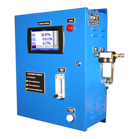
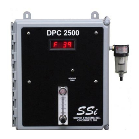
Super Systems H2-SGA User manual

Single Gas Analyzer
For CO, CO2, or CH4
OPERATIONS MANUAL
Super Systems Inc.
7205 Edington Drive
Cincinnati, OH 45249
513-772-0060
Fax: 513-772-9466
www.supersystems.com

Super Systems Inc.
Page 2 of 37
Super Systems Inc.
USA Office
Corporate Headquarters:
7205 Edington Drive
Shipping Address:
7245 Edington Drive
Cincinnati, OH 45249
Phone: (513) 772-0060
http://www.supersystems.com
Super Systems Europe
Unit E, Tyburn Trading Estate,
Ashold Farm Road, Birmingham
B24 9QG
UNITED KINGDOM
Phone: +44 (0) 121 306 5180
http://www.supersystemseurope.com
Super Systems México
Sistemas Superiores Integrales S de RL de CV
Acceso IV No. 31 Int. H Parque Industrial
Benito Juarez
C.P. 76120 Queretaro, Qro.
Phone: +52 442 210 2459
http://www.supersystems.com.mx
Super Systems China
No. 369 XianXia Road
Room 703
Shanghai, CHINA
200336
Phone: +86 21 5206 5701/2
http://www.supersystems.cn
Super Systems India Pvt. Ltd.
A-26 Mezzanine Floor, FIEE Complex,
Okhla Indl. Area, Phase –2
New Delhi, India 110 020
Phone: +91 11 41050097
http://www.supersystemsindia.com

Single Gas Analyzer (SGA)
Operations Manual
Super Systems Inc.
Page 3 of 37
Table of Contents
Introduction..................................................................................................................................... 5
Specifications.................................................................................................................................. 5
Single Gas Analyzer (SGA)........................................................................................................... 5
Mechanical Diagrams ..................................................................................................................... 6
Initial Network Configuration ......................................................................................................... 7
nLocateIP Method ....................................................................................................................... 7
Touch Screen Interface................................................................................................................... 8
Main Screen................................................................................................................................. 8
Menu Screen ............................................................................................................................... 8
Trend Chart ................................................................................................................................. 9
Chart Sub Menu..........................................................................................................................11
Instrument Information (Menu Option) ......................................................................................12
Pump Control (Menu Option)......................................................................................................12
Exit Program (Menu Option).......................................................................................................13
Instrument Configuration (Menu Option) ...................................................................................13
Output Configuration (Menu Option) .........................................................................................14
Communications (Menu Option).................................................................................................15
Alarms Setup..............................................................................................................................16
Output Calibration (Menu Option)...............................................................................................17
Overview..................................................................................................................................17
Zero Calibration......................................................................................................................17
Span Calibration .....................................................................................................................18
Sensor Calibration (Menu Option)..............................................................................................18
Overview..................................................................................................................................18
Zero Calibration Procedure....................................................................................................19
Span Calibration Procedure ...................................................................................................19
Digital IO Card (Menu Option).....................................................................................................20
Passcodes (Menu Option)...........................................................................................................20
Control Interface via Web Browser................................................................................................21
Main............................................................................................................................................21
Instrument Information..............................................................................................................22
Sensor Information ....................................................................................................................23
Instrument Configuration...........................................................................................................24
Output Configuration..................................................................................................................25

Single Gas Analyzer (SGA)
Operations Manual
Super Systems Inc.
Page 4 of 37
Output Calibration ......................................................................................................................26
Sensor Calibration......................................................................................................................27
Alarms........................................................................................................................................28
SSI Configuration .......................................................................................................................29
Read/Write Registers.................................................................................................................30
Network Configuration...............................................................................................................31
Replacement Parts ........................................................................................................................32
Warranty.........................................................................................................................................33
Revision History .............................................................................................................................34

Single Gas Analyzer (SGA)
Operations Manual
Super Systems Inc.
Page 5 of 37
Introduction
SSi provides single gas analysis technology for use in heat treating and other production
environments. The Single Gas Analyzer (SGA) includes a color touch screen and detection cell
with intelligent electronics contained in a metal enclosure designed for rugged industrial
environments. The SGA is preconfigured for detection of CO, CO2, or CH4, depending on
customer needs. Trend charting is available via the touch screen. Control and monitoring are
possible with the touch screen interface and Ethernet-based web interface.
The SGA also includes onboard datalogging and communications via serial connection, USB, or
Ethernet.
Specifications
Gas Measurement Specifications
CO2Sensor
Standard Range
0 –2.000%
Optional High Range
0 –20.00%
Accuracy (Standard Range)
±0.006%
Accuracy (High Range)
±0.2%
Resolution (Standard Range)
±0.001%
Resolution (High Range)
±0.01%
Measurement Method
Non-Dispersive Infrared (NDIR)
CO Sensor
Range
0 –100.00%
Accuracy
±0.2%
Resolution
±0.01%
Measurement Method
Non-Dispersive Infrared (NDIR)
CH4Sensor
Range
0 –100.00%
Accuracy
±0.2%
Resolution
±0.01%
Measurement Method
Non-Dispersive Infrared (NDIR)
Single Gas Analyzer (SGA)
Response Time
0 –6 seconds
Power Supply Input Voltage
110VAC or 230VAC
Maximum Operating Temperature
122 °F (50 °C)
Analog Outputs
2 (4-20mA or 0-5 V)
Serial Communications
2 RS485 ports using Modbus RTU,
configurable baud rate
Ethernet
1 port
USB
1 Type A port, 1 Type B port

Single Gas Analyzer (SGA)
Operations Manual
Super Systems Inc.
Page 6 of 37
Mechanical Diagrams

Single Gas Analyzer (SGA)
Operations Manual
Super Systems Inc.
Page 7 of 37
Initial Network Configuration
This section is intended for use by persons familiar with Ethernet network setup.
In order to work correctly, the unit must be properly configured for the network to which it is
connected. To locate the unit’s IP address, first connect the unit to an Ethernet network using
the appropriate cable.
If you already know the IP address of the web interface, skip to the
Read/Write Registers
The Read/Write Registers page gives access to the underlying Modbus registers of the SGA.
This page is primarily intended for testing and troubleshooting purposes.
Please contact SSi before attempting to make any changes to the settings on this page.

Single Gas Analyzer (SGA)
Operations Manual
Super Systems Inc.
Page 8 of 37
Network Configuration section on page 28. The network configuration is described in this
section.
The IP address of the unit can be found by using SSi’s
nLocateIP
software. This method is
described in the following subsection.
nLocateIP Method
Once the unit is connected to the network, you should be able to locate it on the network using
SSi’s
nLocateIP
software. This program is available from SSi. To use it in locating the unit on
the network, follow these steps on a Windows-based PC:
1. Ensure that the unit is connected to the
network.
2. Open the
nLocateIP
program.
Figure 1 - Opening nLocateIP program
3. Once the program opens, click the Search
button. The program will begin searching
for SSi devices connected to the network.
Figure 2 - Search button in nLocateIP
4. Look for identifying text in the list of
instruments. The corresponding IP address
is the IP address that you will want to use.
Once you have found the IP address, you should be able to complete any additional network
configuration using the web interface. See the

Single Gas Analyzer (SGA)
Operations Manual
Super Systems Inc.
Page 9 of 37
Read/Write Registers
The Read/Write Registers page gives access to the underlying Modbus registers of the SGA.
This page is primarily intended for testing and troubleshooting purposes.
Please contact SSi before attempting to make any changes to the settings on this page.

Single Gas Analyzer (SGA)
Operations Manual
Super Systems Inc.
Page 10 of 37
Network Configuration section on page 28.
If you are unable to find the unit in the list of devices, it is possible that a network setting (such
as subnet mask) may be different, the unit may be connected to a different network, or the unit
may not be powered on. SSi recommends consulting an IT engineer or network administrator.
If needed, call SSi at (513) 772-0060.
Touch Screen Interface
Main Screen
The Main screen shows the current percentage of CO2. From here the user can enter the Menu
screen or the Chart screen.
Menu Screen

Single Gas Analyzer (SGA)
Operations Manual
Super Systems Inc.
Page 11 of 37
The Menu screen allows the user to log in to gain access to additional functions. Pressing the
Login key at the bottom of the screen will allow the user to enter a login user and password.
User names and passwords are case sensitive. There are three levels of security for the menu
system: Operator, Supervisor, and Administrator. Pressing the Login button will allow the user
to enter a user name and numeric password to log in. When the menu screen is first displayed,
the operator-level menu options are visible. The supervisor menu options will be displayed with
the login number 1. The Administrator menu options will be displayed with the login number 2.
To select a menu option, tap on the touch screen to highlight it, then tap the Detail button.
The Menu options are described later in the manual.
Trend Chart
The Chart Display shows between 1 hour and 24 hours of chart data on the screen and can be
scrolled back to view all of the data stored on the hard drive. The vertical timelines change as
the time changes on the screen.
The function buttons run along the bottom of the screen.
The folder button - - stores saved templates. A different chart template can be selected here.
The calendar button - - allows the user to view information for a specific date.
The Trend Lines button - - will allow the user to select or de-select the trend lines on the trend
chart to display. If the checkbox next to each trend line is checked, then that trend line will be displayed.

Single Gas Analyzer (SGA)
Operations Manual
Super Systems Inc.
Page 12 of 37
The Datagrid View button - - will display a screen with the trend data in a grid format instead of with
trend lines. The trend data is shown in 1-minute intervals.
Clicking on the OK button on this screen will close the screen down and return to the Chart Display screen.
The Refresh button - - will refresh the screen’s trend data if the screen is not in real-time mode.
The left-pointing green arrow button - - will move the chart’s view backward in time by the specified
chart interval.
The chart interval button - - will determine the number of hours displayed on the trend chart.

Single Gas Analyzer (SGA)
Operations Manual
Super Systems Inc.
Page 13 of 37
The options are: 1 Hour, 2 Hours, 4 Hours, 8 Hours, 12 Hours, or 24 Hours.
The right-pointing green arrow button - - will move the chart’s view forward in time by the specified
chart interval.
The play/pause button - - will put the chart into real-time mode if it is not in real-time mode, or
take the chart out of real-time mode if it is. When in real-time mode, the chart will automatically be updated
once a minute.
Chart Sub Menu
There is a sub-menu available by putting a finger or a stylus anywhere on the chart and
holding it there for two seconds.
The sub-menu will have the following options available: Zoom, Restore, Add Note, Data, and Exit.
The Zoom option will allow the user to zoom in on a particular part of the screen. Once this has been
selected, the user can take a stylus or a finger and create a box around the desired data. Once the user
releases the stylus or finger, a zoom is no longer possible, and the user will need to re-select the option
from the sub-menu to zoom in again.
The Restore option will back out of any zoom options that have been performed and display the chart screen
as it initially was.
The Add Note option allows the operator to enter a note on the chart, similar to writing on a paper chart.
The note shows up when the chart is printed out using the utility software included with the Series 9220
instrumentation. Pressing the Add Note option displays a screen where the operator can enter the operator
ID or initials and a note. The user has the option to enter a note using the operator interface keyboard,
where he or she will be able to type in the note; or the user can use the Signature mode, which will allow
them to write a note using a stylus.

Single Gas Analyzer (SGA)
Operations Manual
Super Systems Inc.
Page 14 of 37
The Data option will show the trend data as a data grid instead of the trend lines on a chart. This
functionality is exactly the same as if the user pressed the Datagrid View button - - from the chart
screen.
Exit will close out the sub-menu without selecting an item.
Pressing the red ‘X’ in the top right-hand corner of the screen will take the user back to the status screen.
Instrument Information (Menu Option)
The Instrument Information screen provides basic information about the unit, including
Desciption, Part #, Serial #, Sub Serial #, Main Version #, and Sensor Version #.
Pump Control (Menu Option)

Single Gas Analyzer (SGA)
Operations Manual
Super Systems Inc.
Page 15 of 37
The Pump Control screen allows the user to turn the pump on or off. The current pump status
will be displayed on the screen. To change the status, tap the “Set Pump” button, select “On” or
“Off,” and tap “Select.” To exit the screen without changing the pump status, tap “Cancel.”
Exit Program (Menu Option)
The Exit Program option allows the user to shut down the SGA touchscreen, after a
confirmation dialog box is displayed.
Instrument Configuration (Menu Option)

Single Gas Analyzer (SGA)
Operations Manual
Super Systems Inc.
Page 16 of 37
Select Device Time to set the internal time of the sensor.
Output Configuration (Menu Option)
The SGA has two outputs. These can be configured for Source, Zero Value, Span Value, Range,
and Manual.
The Source is the gas that applies to that output (NDIR Gas or External).

Single Gas Analyzer (SGA)
Operations Manual
Super Systems Inc.
Page 17 of 37
The Zero Value is the NDIR gas % value that corresponds to 4mA on a 4-20mA scale. (4-20mA
is the default Range setting. If Range is set to 0-20mA, then the Zero Value refers to 0mA.)
The Span Value is the NDIR gas % value that corresponds to 20mA on a 4-20mA scale. (4-20mA
is the default Range setting. If Range is set to 0-20mA, then the Span Value still refers to
20mA.)
Range allows the user to choose between an output signal of 4-20mA (default) and 0-20mA.
Manual allows the user to enter an output value to test the analog output. In order for this
option to function, Source must be set to External.
To change an item, tap the desired row, then tap “Edit.” Enter the desired value in the “Input”
box (or make a selection from the dropdown menu) and click the “OK” button. Your new value
will be displayed on the Output Configuration screen.
Communications (Menu Option)
NOTE: Please consult with your network administrator or an IT professional before making
changes to the Communications screen.
The Communications menu allows the user to set the IP Address, Subnet Mask, and Gateway
for the SGA. To change these values, tap the desired row, then tap “Edit.” Enter the new value

Single Gas Analyzer (SGA)
Operations Manual
Super Systems Inc.
Page 18 of 37
on the ensuing screen, then tap “OK.” Your new value will be displayed on the Communications
screen.
Do not change these values without consulting your IT professional. Doing so could cause IP
conflicts and other network issues.
Alarms Setup
The Alarms option allows you to set lower and upper limits and assign actions to readings for
the SGA.

Single Gas Analyzer (SGA)
Operations Manual
Super Systems Inc.
Page 19 of 37
Tap to highligh the desired gas type. Then tap the appropriate buttons to enter a Lower Limit
and an Upper Limit. To select an Action, tap “Set Action” to cycle through the available options.
There are four possible actions for the alarms:
“None” will not energize any relays.
“AL1” will energize Relay 3;
“AL2” will energize Relay 4;
“Both” will energize Relays 3 and 4.
Output Calibration (Menu Option)
Overview
The Output Calibration screen allows the user to perform a zero/span calibration on the analog
outputs.

Single Gas Analyzer (SGA)
Operations Manual
Super Systems Inc.
Page 20 of 37
The Output Calibration screen allows the user to perform a zero/span calibration. The SGA is
equipped with two analog outputs. These outputs require calibration to ensure that the mA
signal corresponds to a given output value (zero value for the lowest value and span value for
the highest value). SSi recommends output calibration be performed on each output at least
once per year, or as needed.
To calibrate each output, first make sure that you have a multimeter (or other appropriate
testing instrument) available. Then follow these steps.
Zero Calibration
To calibrate the zero/span range for an output:
1. Attach a measuring device to the selected output.
2. Select “Output Calibration” from the Main Menu.
3. Once this is done, tap to highlight “Zero/Span,” then tap the “Toggle Zero/Span” button to
select “Zero.” “Zero” will now be displayed in the Zero/Span row.
4. To select the desired output, tap to highlight “Output#,” then tap the “Toggle Output
Number” button to select the appropriate setting. The current value will be displayed in the
“Output#” row.
5. Tap to highlight “Prep for Cal” and tap the “Prep for Cal” button.
6. Let the unit output what it has set for the zero measurement, and note the reading on your
attached measuring device.
7. Tap “Measured value (mA)” and tap the “Edit mA” button.
8. Enter the measured value and tap “OK.”
9. Then, tap “Run Cal” and tap the “Run Cal” button.
Span Calibration
To calibrate the span:
1. Use the “Toggle Zero/Span” button to select “Span.”
2. Tap to highlight “Prep for Cal” and tap the “Prep for Cal” button.
3. Let the unit output what it has set for the span measurement, and note the reading on
your attached measuring device.
4. Tap “Measured value (mA)” and tap the “Edit mA” button.
5. Enter the measured value and tap “OK.”
6. Then, tap “Run Cal” and tap the “Run Cal” button.
Sensor Calibration (Menu Option)
Table of contents
Other Super Systems Measuring Instrument manuals
Popular Measuring Instrument manuals by other brands

Oricom
Oricom TPS10 operating instructions

Dwyer Instruments
Dwyer Instruments RVM Specifications-installation and operating instructions

Unit
Unit UT381 operating manual

CARLO GAVAZZI
CARLO GAVAZZI WM5-96 - PROGRAMMING instruction manual

Fluke
Fluke CPS-40M-HC40 instructions

BEKA
BEKA Advisor A70 instruction manual