Superabrasive LAVINA 20-S-E User manual

LAVINA® 20-S-E User Manual
www.superabrasive.com / factory@superabrasive.com

Superabrasive UserManual OriginalLanguageLavina®20‐S‐E 9/2014
2
1.GENERALINFORMATION............................................................3
MANUFACTURER...........................................................................3
GENERALDESCRIPTION..................................................................3
MACHINECHARACTERISTICS..........................................................3
MAINDESIGN.................................................................................3
ENVIRONMENTALCONDITIONS.....................................................3
ELECTRICALCONNECTION..............................................................3
VACUUMCONNECTION.................................................................4
TECHNICALDATA...........................................................................4
CE‐CERTIFICATION..........................................................................4
VIBRATIONS...................................................................................4
SONOROUSEMISSIONS..................................................................4
LABELDATA...................................................................................4
CUSTOMERSERVICE.......................................................................4
2.SAFETYINSTRUCTIONS...............................................................4
RECOMMENDEDUSE.....................................................................4
PROHIBITEDUSE............................................................................4
FEATUREINCLEMENTCONDITIONS................................................4
POSSESSELECTROMAGNETICRADIATION......................................4
PREPARATIONFORWORK.............................................................4
ARRESTFUNCTIONS.......................................................................5
SAFEUSE........................................................................................5
RESIDUALRISKS.............................................................................5
BEFOREYOUBEGIN........................................................................5
OPERATINGMACHINE..................................................................5
AFTERWORKISCOMPLETED...........................................5
THEWORKAREA..........................................................5
PERSONALPROTECTIVE.................................................5
EQUIPMENT(PPE)..........................................................................5
OPERATOR................................................................................5
3.HANDLINGANDTRANSPORTATION...........................................6
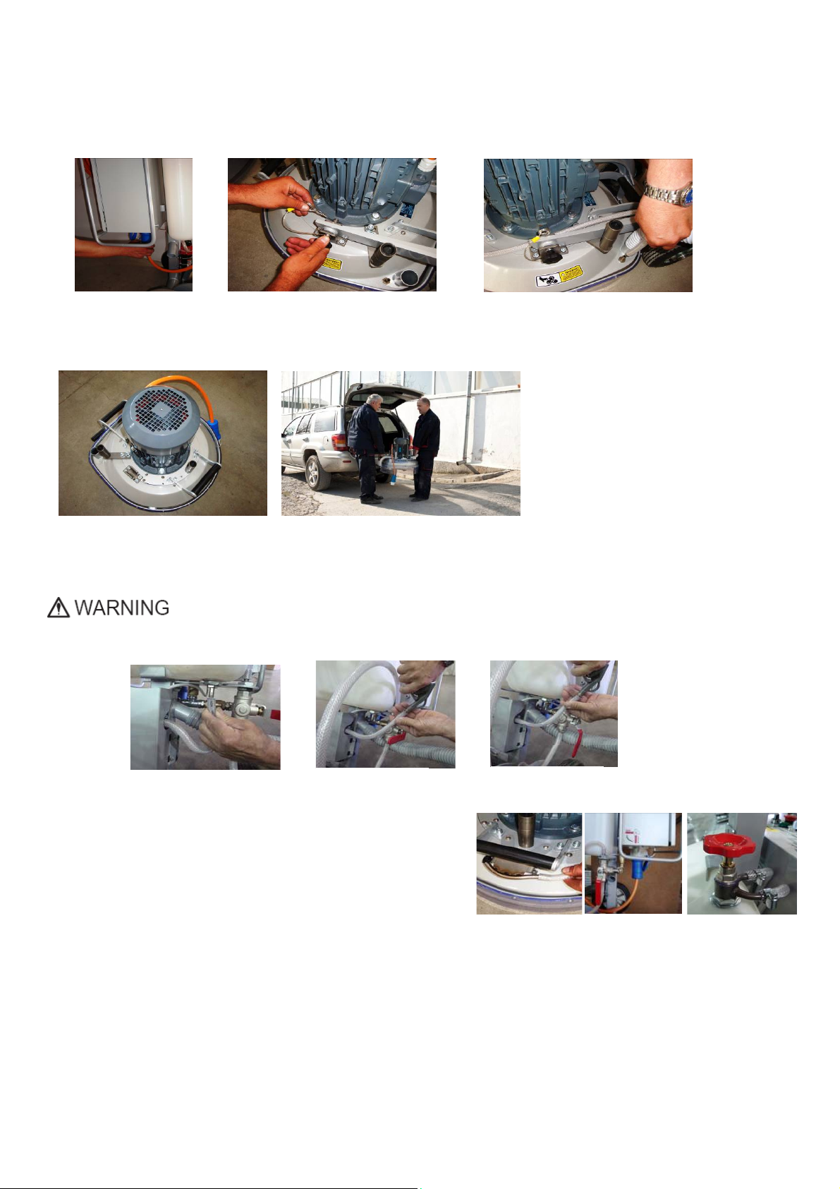
PREPARINGTHEMACHINEFORTRANSPORTATION.......................6
STORAGE........................................................................................6
4.OPERATION................................................................................6
PRELIMINARYCONTROLS...............................................................6
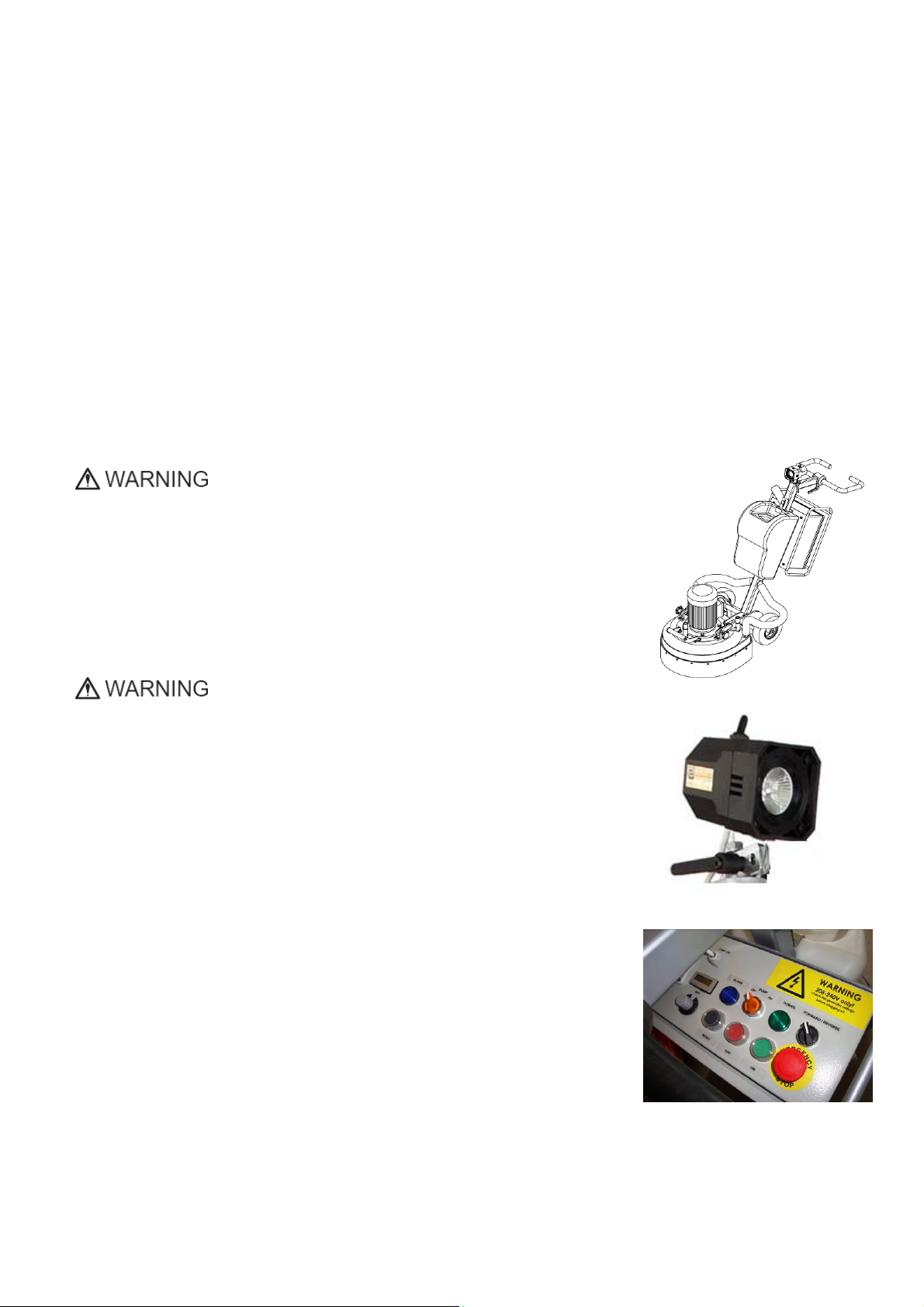
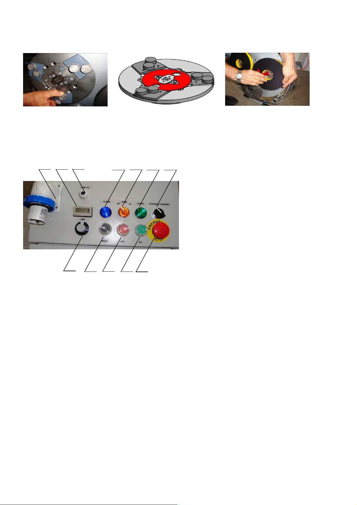
THECONTROLBOARD....................................................................7
STARTINGTHEMACHINE...............................................................7
5.TOOLSANDACCESSORIES..........................................................8
WEIGHTS........................................................................................8
TOOLHOLDERKEY.........................................................................8
FOAMPLATE..................................................................................8
6.POPULARTOOLS........................................................................9
RECOMMENDEDTOOLS.................................................................9
7.EXPLODEDVIEW......................................................................10
GENERALEXPLODEDVIEW(FIG.7.1)............................................10
MAINHEADEXPLODEDVIEW(FIG.7.2)........................................10
TOPCOVEREXPLODEDVIEW1(FIG.7.3)......................................10
TOPCOVEREXPLODEDVIEW2(FIG.7.4)......................................10
BOTTOMCOVEREXPLODEDVIEW1(FIG.7.5)..............................11
PLANETARYDRIVEEXPLODEDVIEW(FIG.7.6)..............................11
BOTTOMCOVEREXPLODEDVIEW2(FIG.7.7)..............................11
PULLEYUNITSEXPLODEDVIEW(FIG.7.8).....................................11
CARRIAGEEXPLODEDVIEW(FIG.7.9)...........................................11
TOOLHOLDEREXPLODEDVIEW(FIG.7.10)...................................11
8.MAINTENANCEANDINSPECTION............................................12
CLEANING....................................................................................12
ELECTRICALSYSTEM.....................................................................12
LAVINA®20‐S‐EELECTRICALSCHEMESWITHYASKAWA
INVERTER...................................................................................13
INDEXOFPROBLEMSANDSOLUTIONS........................................14
9.2DISMOUNTINGANDMOUNTINGTOOLHOLDERTOCHANGE
BUFFERSANDSPIDERS,CHANGINGV‐RINGSANDFELT‐RINGS....14
9.3TENSIONINGANDREPLACETHEPLANETARYBELT.................15
9.4TENSIONINGUSEDPLANETARYBELT.....................................15
9.5MOUNTINGANDTENSIONINGANEWPLANETARYBELT.......15
9.6REPLACINGPULLEYUNITS......................................................16
9.7MOUNTINGTHEBELT.............................................................18
9.8CHECKINGTHETENSIONOFTHEBELT....................................19
9.9MOTORCONNECTION............................................................19
9.10FAULTDIAGNOSISINVERTERYASKAWAV1000...................20
WARRANTYPOLICYFORTHELAVINA®S‐EMACHINE..................23
RETURNPOLICYFORLAVINA®S‐EMACHINES.............................23
ASSEMBLYANDPARTSSPECIFICATIONS......................................24
1.LAVINA®20‐S‐EGENERALPARTS
FORMACHINESPRODUCEDBEFOREJAN.12014........................24
1.LAVINA®20‐S‐EGENERALPARTS/FORMACHINESPRODUCED
AFRTERJAN.12014/..................................................................24
2.LAVINA®20‐S‐ETOPCOVERPARTS1.......................................25
3.LAVINA®20‐S‐EGUARDPARTS................................................25
4.LAVINA®20‐S‐ETOPCOVERPARTS2.......................................25
5.LAVINA®20‐S‐ETOPCOVERPARTS3.......................................26
6.LAVINA®20‐S‐EBOTTOMCOVERPARTS1...............................26
7.LAVINA®20‐S‐EPLANETARYDRIVEPARTS...............................26
8.LAVINA®20‐S‐EBOTTOMCOVERPARTS2...............................27
10.LAVINA®20‐S‐ETOOLHOLDERPARTS....................................28
11.LAVINA®20‐S‐EWATERSUPPLYPARTS
FORMACHINESPRODUCEDBEFOREJAN.12014........................28
11.LAVINA®20‐S‐EWATERTANKPARTS
FORMACHINESPRODUCEDAFTERJAN.12014..........................28
13.LAVINA®20‐S‐ECONTROLBOXPARTS200‐240VOLT...........31

Superabrasive UserManual OriginalLanguageLavina®20‐S‐E 9/2014
3
1.GENERALINFORMATION
Thisowner’smanualisintendedfortheoperatoroftheLavina®S‐Emachine,theservicingtechnicianaswellasforanyone
involvedwithoperatingorservicingthemachine.Werecommendthatyoureadtheinstructionsverycarefullyandfollowthem
strictly.
Themanualincludesinformationaboutassembling,using,handling,adjustingandmaintainingyourLavina®S‐Efloorgrinding
andpolishingmachine.
MANUFACTURER
Superabrasivewasfoundedin1987,asamanufacturerofhighqualitydiamondtoolsforthestoneandconcreteindustry.
Today,Superabrasiveisoneoftheworld’sleadingcompaniesintheproductionofdiamondtoolsandfloorgrindingmachinery.
AtSuperabrasive,westrivetodelivertheverybestsolutionstoourcustomers,andenablethemtoworkmoreefficiently.
GENERALDESCRIPTION
TheLavina®S‐Emachineisintendedforgrinding,polishingandbuffingconcrete,marble,granite,limestoneandterrazzosurfaces
withdiamondtools.
TheLavina®S‐Emachineisathree‐discmachine,whichcanbeuseddryaswellaswet.
Forbestresults,useonlytoolsmanufacturedorrecommendedbySuperabrasiveanditsdistributors.Additionally,themachine
couldbeusedforgrindingwoodfloorsurfaces.
TheLavina®S‐Emachineismanufacturedandfittedfortheabove‐
mentionedapplicationsonly!Everyotherusemaycauseriskstothepersonsinvolved.
MACHINECHARACTERISTICS
TheLavina®S‐Emachineismadeoftwomaincomponentsections:
MAINDESIGN
Thetwomaincomponentsectionsarethecarriageandmainhead.
Thehandle(Fig.1.2)ontheframecanbeadjustedbyheightandallowstheoperatorto
workinacorrectandsafeworkingposture.
Thehalogenspotlight(Fig.1.2)enablestheoperatortoworkindarkerareas.
Existinglightingsystemdoesnotreplaceadequateoverhead
lighting.
Theframe
Thecontrolsarepositionedontopoftheelectricalbox(fig.1.3)
Theelectricalbox(fig.1.3)containstheelectricswitchingdevicesandthe
inverter.Themainfeedingcableisconnectedwithaplugandsocketontop.Themotor
feedingcableispluggedintothesocketlocatedonthebottomofthebox.Thetankison
theoppositesideoftheframe,sothattheweightofthewaterhasnoinfluenceonthe
operationofthemachine.Theframeweight,ontheotherhand,isfullyabsorbedbythe
drivingwheels.Anelectricpumpspraysthewaterthroughafrontsprayer.Themotoris
mountedonthebaseplateandisdrivingthethreeheadswithabeltsystem.The
planetaryheadisdrivenbyasecondflatbelt.
ENVIRONMENTALCONDITIONS
ThetemperaturerangeforoperatingtheLavina®S‐Emachineoutdoorsisbetween41°F
and86°For5°Cand30°C.NeverusetheLavina®S‐Emachineduringrainorsnowwhen
workingoutdoors.Whenworkingindoors,alwaysoperatethemachineinwell‐ventilated
areas.
ELECTRICALCONNECTION
Thevoltage(Volt)andpower(Ampere)aredisplayedonalabelontheelectricalcontrol
boxtoavoidanyincorrectconnection.Refertothesebeforeconnectingthepower.To
avoidelectricalshocks,makesurethegroundpowersupplyisfunctioningproperly.
Figure 1.3
Fi
g
ure 1.1
Figure 1.2

Superabrasive UserManual OriginalLanguageLavina®20‐S‐E 9/2014
4
VACUUMCONNECTION
Aconnectionforavacuumdustextractorislocatedonthecarriage.TheLavina®S‐Emachinedoesnotincludeavacuumdust
extractor.Thecustomermustpurchasethevacuumdustextractorseparately.ThehoseofthevacuumextractormustbeØ50.8
mmandcanbeglidedoverthepipe.Thevacuumdustextractormustbeadaptedforfloorgrindersandhaveaminimumair
displacementof320m3/hwithanegativevacuumof21kPa.
TECHNICALDATA
CE‐CERTIFICATION
TheLavina®S‐Emachineisdesignedtooperate
correctlyinanelectromagneticatmosphereof
industrialtypeandisequippedwithallthe
mechanicalandelectricalsafetyprotectionsin
conformitywiththefollowingEuropeanCEErules
andregulations:
TheLavina®S‐EmachinecomplieswiththeSafety
Directiveformachines2006/42/EC,theEMC
Directive2004/108/ECandtheLowVoltage
Directive2006/95/EC.
AlsocomplieswiththenormsinuseBDSENISO
12100,BDSEN13862,BDSENISO13857,BDSEN
349,BDSENISO13850,BDSEN13732‐1,BDSEN
953,BDSENISO13849‐1,BDSEN1037,BDSENISO
5349‐1,BDSENISO11201,BDSENISO3744,BDS
EN1033:2002,BDSEN60204‐1,BDSEN1837,BDSEN61000‐6‐4,BDSEN61000‐6‐2,BDSEN61000‐4‐2,BDSEN61000‐4‐4,BDS
EN61000‐4‐5,BDSEN61000‐4‐11,BDSEN55016‐2‐1
Testresultsareapartofthemachine’stechnicalinformationandcanbesentuponaspecialrequest.Themachineisdelivered
withtheCEmarkexposedandprovidedwithaECdeclarationofconformity.
VIBRATIONS
Themeasuredvibrationvalueonthesurfaceofgrippingincaseofguidingthemachineisahw=2,95m/s2.Themeasurementis
madeinaccordancewiththeBDSENISO1033andBDSENISO5349‐1.
SONOROUSEMISSIONS
Themaximumnoiselevelatdistanceofthemachineof1mincaseofworkingatidledoesnotexceed70db(a).Themeasurementismadein
accordancewiththebdseniso11201andbdseniso3744.
LABELDATA
ThedataonthelabelprovidesthecorrectVoltageandkW(neededforoperationalpurposes);
Weight(neededfortransportationpurposes);productionyearandserialnumber(neededformaintenancepurposes).
CUSTOMERSERVICE
ForcustomerassistanceandtechnicalsupportcontactyourlocaldistributororcontacttheproducerSuperabrasiveLtd.orvisitus
atwww.superabrasive.com,whereyoucandownloadacopyofthismanual.
2.SAFETYINSTRUCTIONS
RECOMMENDEDUSE
TheLavina®S‐Emachineis
designedandmanufacturedtogrindandpolishconcrete,
terrazzo,andnaturalstonefloors.Itcanbeusedforrenovations
aswellasforpolishing.Themachineisdesignedfordryorwet
use.Whenusingitdry,useavacuumofappropriatesize.For
moreinformation,pleaserefertothechapteronhandlingthe
vacuumconnection.
PROHIBITEDUSE
ThemachineMUSTNOTbeused:
ForapplicationsdifferentfromtheonesstatedintheGeneral
Descriptionchapter.
Fornon‐suitablematerials.
Inenvironmentswhich:
Possessrisksofexplosion
Possesshighconcentrationofpowdersoroilsubstancesinthe
air
Possessrisksoffire
Featureinclementconditions.
Possesselectromagneticradiation.
PREPARATIONFORWORK
Makesurethat:Youhaveclosedtheworkarea,sothatno
personunfamiliarwithoperatingthemachinecanenterthe
Lavina®20‐S‐E
Voltage/Hz1phx200‐240V50‐60Hz
AmperageMax14 Amps
Power3kW4HP
Toolholderrpm300‐1100rpm
Workingwidth510mm20”
Tooldiameter(QCPlate)3x225mm3x9”
Weight162kg357 lbs
Grindingpressure80kg177 lbs
Additionalweightmax1x22kgmax1x48 lbs
Applicationwetanddry
VacuumhoseportYes
Watertankcapacity20l5.2gal
Waterfeedwithpump(peripheralandfront)
Cablelength17.4m57ft
MachineLxWxH1350x540x1100mm53.1”x21.3”x43.3”
PackingLxWxH1150x730x1155mm45.2”x28.7”x45.5”

Superabrasive UserManual OriginalLanguageLavina®20‐S‐E 9/2014
5
area.Thetoolplateandtoolsareadjustedtothemachine
properly.Therearenomissingpartsofthemachine
Themachineisinuprightworkingposition.Theprotection
devicesareworkingproperly.Theelectricalcableisfreetomove
andfollowthemachineeasily.Inordertokeeptheelectrical
cablefrombeingdamaged,novehicleshouldcrossthezone
whereelectricalcablesaresituated.
PROTECTIONDEVICES
Themachineisequippedwith
severalprotectiondevicesincludingthefollowing:
Anemergencystopbutton
Aprotectionskirtandahoodforprotectingthetoolplates.
Thesedevicesprotecttheoperatorand/orotherspersonsfrom
potentialinjuries.Donotremovethem.Oncontrary,before
usingthemachine,pleaseensurethatallprotectiondevicesare
mountedandfunctionproperly.TheSecurityplateavoidthe
Quickchangepadstolooseduringwork
ARRESTFUNCTIONS
Functionsofarrestingofthe
machinearefollowing:
Buttontostopthemotor(category1)
Emergencybutton(category1)
SAFEUSE
TheLavina®S‐Eisdesignedto
eliminateallriskscorrelatedwithitsuse.However,itisnot
possibletoeliminatetherisksofanaccidentwiththemachine.
Anunskilledoruninstructedoperatormaycausecorrelated
residualrisks.Suchrisksare:
PositionRisksduetooperator’sincorrectworkingposition
TanglingupRisksduetowearinginappropriateworkingclothes
TrainingRisksduetolackofoperationaltraining
NOTE:Inordertoreduceallconsequencesoftheabove‐
mentionedrisks,weadvisethatmachineoperatorswillfollow
theinstructionsinthemanualatalltimes.
RESIDUALRISKS
Duringthenormaloperating
andmaintenancecycles,the
operatorisexposedtofewresidualrisks,whichcannotbe
eliminatedduetothenatureoftheoperations.
BEFOREYOUBEGIN
Workingareamustbeclear
fromanydebrisorobjects.
Afirst‐timeoperatormustalwaysreadthemanualandpay
attentiontoallsafetyinstructions.
Allelectricconnectionsandcablesmustbeinspectedfor
potentialdamages.
Groundwiresystemofthepowersupplymustbealsoinspected.
Performgeneraldailyinspectionsofthemachineandinspect
themachinebeforeeachuse.
Alwaysinspectthesafetydevices:MounttheSecurityplatefor
theQuickchangepads.
Theemergencybreakmustbeclearandworking
Thetoolprotectormustbeworking
Themachinemustbeclean
Neveroperatethemachineintherain!
Confirmthattherearenomissingpartsespecially
aftertransportation,repair,ormaintenance.
Beforefillingthewatertankwithwatermakesurethe
machineisnotworkingandthemainswitchisturnedoff.
Beforeturningonthemachinemakesurethatthebaseis
placedonthefloor,themachineMUSTNOTbeinan
uprightpositionwhenturnedon!
OPERATINGMACHINE
WhenoperatingtheLavina®S,makecertainthatthereisnoone,
butyouaroundthemachine.
Neverleavethemachineunattendedwhileworking.
Theelectricalcablemustmovefreelyandmustbedamage‐free.
Thewaterhosemustmovefreelyandmustbedamage‐free.
Checkifthefloor,youworkon,isnottoouneven.Ifthisisthe
case,itmaydamagethemachine.
AFTERWORKISCOMPLETED
Cleanthemachineanditssurroundingsproperly
Emptyandcleanthewatertank
Unplugthemachineandwinduptheelectricalcable
Storethemachineinasafeplace
THEWORKAREA
Makecertainthatpeopleorvehiclesdonotenterthework
area.
Avoidcablesandhosesbeinginthe
way.Alwayscheckthefloorfordebris
PERSONALPROTECTIVE
EQUIPMENT(PPE)
Alwayswearsafetyshoeswhenworkingwiththemachine.
Alwayswearearprotectorswhenworkingwiththe
machine.Allpersonnelintheimmediateworkareamust
wearsafetyglasseswithsideshields.
Alwayswearsafetygloveswhenchangingthetools.
Alwayswearclothessuitablefortheworkenvironment.
OPERATOR
TheLavina®S‐Emachine.
Theoperatormustknowthemachine’swork
environment.Onlyoneoperatoratatimecanworkwith
themachine.Theoperatormustbeproperlytrainedand
wellinstructedprioroperatingthemachine.
Theoperatormustunderstandalltheinstructionsin
thismanual.
Theoperatormustunderstandandinterpretallthe
drawingsanddesignsinmanual.
Theoperatormustknowallsanitationandsafetyregulations
pertainingtotheoperationofthemachine
Theoperatormusthavefloorgrindingexperience.
Theoperatormustknowwhattodoincaseofemergency.
Theoperatormusthaveanadequatetechnicalknowledgeand
preparation.

Superabrasive UserManual OriginalLanguageLavina®20‐S‐E 9/2014
6
3.HANDLINGANDTRANSPORTATION
PREPARINGTHEMACHINEFORTRANSPORTATION
Unplugthemotorcableplugfromthecontrolbox(Fig.3.1)anddisconnectthewaterhosefromthemainheadbypullingitout
(Fig.3.2).Windtheelectricalcableonthecarriage.Releasethepinsets(Fig.3.3)whichattachtheheadtothecarriage.
Pulloutthevacuumhoses,anddismountthe
headfromthecarriage(Fig.3.4).
TheheadoftheLavina®S‐Emachinehas
onebarandasupportusedashandles
intendedforeasymovingand
transportation(Fig.3.4).TheLavina®S‐E
machineisengineeredwitheasy
transportationinmind.Theabilityto
dismantlethemachineintwopartsallows
convenienttransportationandstorage
(Fig.3.4,Fig.3.5).
STORAGE
AlwaysstoreandtransporttheLavina®S‐Emachineinadryplace.NevertransporttheLavina®S‐Emachineunprotected;it
maybedamagediftransportedunprotectedduringrainorsnow.
Whenstoringthemachine,thetemperaturemayfalldowntoorlessthan32F(or0oC),thereforeyou
shouldemptythewaterfromthesystemusingfollowingsteps:
‐ Pulloutthehoseofthetank(Fig.3.6)
‐ Usingcompressedairblowoutthewaterfromthesystemforthetwopositionsoftheturn‐cock(Fig.3.7,Fig.3.8).
4.OPERATION
PRELIMINARYCONTROLS
Inspecttheworkingareaasexplainedinthesafetyinstructions.Forwet
use,fillinthewatertankwhentheelectricalcableisdisconnected.
Connect
thevacuumextractorandensurethatthevacuumhoseisclearanditwill
followthemachineeasily.Pluginthemachineandmakesurethatthe
powercordisfreetofollowtheworkingdirectionoftheLavina®S‐E
machine.
WATERFLOWCONTROLUNIT
Theoperatorcanchoosethewaterspraysinthefront(Fig.4.1)whenthelevelofthetapisinthehorizontalposition(Fig.4.2),when
thelevelisintheverticalposition(Fig.4.2)waterwillsprayundercoverofthemachine.
Theflowregulatingvalvelocatedonthetank(Fig.4.3)isincreasingorreducingthewaterflowtotheworkingarea–infrontofthe
machineorunderthemainheadcoverofthemachine/onlyformachinesproducedafterJan.12014/.
Figure 3.4 Figure 3.5
Figure 3.1 Figure 3.3
Figure 3.2
Fi
g
ure 3.6 Fi
g
ure 3.7 Fi
g
ure 3.8
Figure 4.2 Figure 4.3
Figure 4.1

Superabrasive UserManual OriginalLanguageLavina®20‐S‐E 9/2014
7
AdjustingandMountingTools
Mountthetoolsonlyafterensuringthatthereisenoughdiamondbondmaterialleft.Besurethattheplatesarealwaysclean
beforemounting.(Fig.4.3)
WARNING:Alwayssecurethe“Quickchange”padswiththesecurityplate(Fig.4.3),lockwiththetoolholderkey(Fig.5.4).
DiamondtoolswithVelcroareattachedonthree9inchfoamplates.Thefoamplatesaremountedonthekeylock
(butterfly).Alwaysusethetoolholderkey(Fig.5.4).
THECONTROLBOARD
1. Powercableplug
2. DigitalRPMindicatorIndicatestherevolutionper
minuteofthegrindingplates(nottherevolutionper
minuteoftheentireunit).
3. Lampcablegland
4. InverteralarmledLightsbluewhentheinvertergoes
intoalarmmode.
5. WaterpumpswitchLightsorangewhenthewater
pumpisworking.
6. Powerledlightsgreenwhenthepowerison
7. Forward/Reverseswitchchooseforwardforclockwise
rotationofthegrindingplatesorreverseforanti‐
clockwiserotationofthegrindingplates
8. PotentiometerchangestheRPMofthegrinding
platesfrom300‐1100rpm
9. Resetbuttonresetsthealarmoftheinverter
10. OFFbuttonstopsthemotor
11. ONbuttonstartsthemotor
12. EmergencybuttonusedinEmergencysituationsfor
stoppingthemotor
STARTINGTHEMACHINE
First,followthedirectionsinchapterSafetyDevicesandSafetyInstructions.Next,pulltheemergencystop(12)toensurethatthe
machineisinworkingcondition.Checkthepotentiometer(8)andensurethatitissetattheworkingspeed.Ifworkingwet,add
watertothefloorsurface.Ifworkingdry,omitthisstep,andinstead,switchonthevacuumunit.Finally,holdthemachinefirmly
andpushthestartbutton(11).
OPERATINGTHEMACHINE
Guidethemachineinstraightlinesacrossthefloor,andwitheachnewlineoverlapalittlebitofthepreviouslycompletedsurface.
Workataconstantspeedallowingthetoolstimetoworkataspeedappropriateforthetools’gritsize.Avoidvibrations.Donotstop
theLavina®S‐Emachineinonespotwhilethetoolsarestillworkingbecausetheywillleavemarksonthefloorsurface.When
workingwet,preliminarychosewiththewatertap(Fig4.2)thepositionforwaterfeedandperiodicallystartthepumptorelease
waterontothefloorsurface(Fig.4.6Pos.5).Whenworkingdry,checkthefloorsurfaceperiodicallytoensurethatdustisnot
accumulatingonthesurface,alsocheckregularlythatyourvacuumworksproperly.
STOPPINGTHEMACHINE
Thestoppingofthemachinemustbedonegraduallyuntilthemotorstops.Donotstopmovingthemachinebeforearrestingthe
Motor,asthetoolscoulddamagethesurface.Tostop,pushtheoffbutton(10).UsetheEmergencybutton(13)onlyinemergency
oruseittoswitchthepowertotallyoff.Remembernottoholdthemachineinonespotbeforeturningoffthemotor.
ALARM
TheAlarmlight(4)willlightincaseinvertergoesinalarmmode.Themostcommonfailureismotorinoverload.Toresetthemode
pushresetbutton(9).
Figure 4.4 Figure 4.6
Figure 4.5
Figure 4.7
1234567
89101112

Superabrasive UserManual OriginalLanguageLavina®20‐S‐E 9/2014
8
5.TOOLSANDACCESSORIES
WEIGHTS
Superabrasiveoffersadditionalweightsforincreasingtheproductivityofthemachine
(Fig.5.1).Eachadditionalweightweighsabout48lbsor22kg.Eachindividualapplication,
typeandconditionofsurface,powercapacityoftheoutlet,etc.willdeterminethe
numberofweightsyoucanusewithout
trippingabreaker.
Theweightstacksontothreepostsaroundtheouterbowl(Fig.5.2).Theadditional
weightsdependonthetools;itisnotalwayspossibletoaddweights.Sometoolswork
tooaggressivelyandthemachinecanstop.Theweightcanbeorderedwithitem
numberA07.00.00.00
TOOLHOLDERKEY
Thetoolholderkey(Fig.5.3)isusedforadjusting,mountinganddismountingofthefoam
plates.Alwaysusethekeyformounting.
ItemnumberisA03.00.00.00
FOAMPLATE
DiamondtoolswithVelcroaremountedonthefoamplate9“(Fig.5.4).Thefoamplateis
mountedonthe“QuickChange”System.
ItemnumberisLV‐9‐FP‐S
SECURITYPLATEFORQUICKCHANGEPADS
Plateusedtoensurethe“Quickchange”pads.
ItemnumberisA38.00.01
Fi
g
ure 5.3
Figure 5.1
Figure 5.5
Figure 5.4
Fi
g
ure 5.2

Superabrasive UserManual OriginalLanguageLavina®20‐S‐E 9/2014
9
6.POPULARTOOLS
RECOMMENDEDTOOLS
QuickChangeSystemandToolingfeatureextremelyfastandconvenienttoolchanges,andalongtool
life,providingforgreatlong‐termcostsavings.TheQuickChangepadsareproducedinfourdifferent
bondsforsuperhard,hard,mediumandsoftconcrete,inavarietyofgritsizes.Theyareofferedwith
1or2buttonsorrectangularsegments,whichallowsyoutocustomizetheaggressivenessofthecut.
Calibragrindingdiscs:ourpopularceramicbonddiscsaredesignedfortheremovalofdifficultscratches
and
theysaveyouvaluabletimebyeliminatingtheneedformultiplepasseswithmetaltools.Theycanbe
usedwet
ordry,andarebestforhardconcreteapplications.
Theyare3‐inch,withincludedVelcrobackattachment.
NATO®polishingdiscsfeatureaspecialresinformuladesignedforbothwetanddryapplicationsandauniquedesignwith
widechannelsallowingforworkonacleanersurfaceandensuringaqualitypolish.Availablein3and4insizes.Theyarewith
includedVelcroattachment.
V‐HARR®PremiumPolishingPadsaredesignedformechanicallypolishingandrestoringconcrete;alsoidealforterrazzoand
hardstonefloors.V‐HARR®padsareofferedinawidevarietyofdiametersandgritsizestoaccommodatemanyapplications.
Dryuseisstronglyrecommended.
ShinePro®arehighqualitydiamond‐impregnatedpadsforfloormaintenance.Availableinavarietyofsizes,andaregreatfor
dailyuse.Whenusedwet,theyrequireonlywater(nowaxorchemicalsneeded)andareaveryenvironmentallyfriendlysolution
formaintainingfloors.
Useonlysuperabrasive’srecommendedtools.Formoretoolingoptions,visitwww.superabrasive.com

Superabrasive UserManual OriginalLanguageLavina®20‐S‐E 9/2014
10
7.EXPLODEDVIEW
GENERALEXPLODEDVIEW(FIG.7.1)
MAINHEADEXPLODEDVIEW(FIG.7.2)
TOPCOVEREXPLODEDVIEW1(FIG.7.3)
TOPCOVEREXPLODEDVIEW2(FIG.7.4)
Figure 7.3
Figure 7.4
Figure 7.1 Figure 7.2

Superabrasive UserManual OriginalLanguageLavina®20‐S‐E 9/2014
11
BOTTOMCOVEREXPLODEDVIEW1(FIG.7.5)
PLANETARYDRIVEEXPLODEDVIEW(FIG.7.6)
BOTTOMCOVEREXPLODEDVIEW2(FIG.7.7)
PULLEYUNITSEXPLODEDVIEW(FIG.7.8)
CARRIAGEEXPLODEDVIEW(FIG.7.9)
TOOLHOLDEREXPLODEDVIEW(FIG.7.10)
Figure 7.9
Figure 7.8
Figure 7.10
Figure 7.6
Figure 7.7
Figure 7.5

Superabrasive UserManual OriginalLanguageLavina®20‐S‐E 9/2014
12
8.MAINTENANCEANDINSPECTION
CLEANING
Keepyourmachineclean.Cleaningthemachineonaregularbasiswillhelpdetectandsolvepotentialproblemsbeforetheycause
damagetothemachine.Mostimportantly,checkandcleanthetoolplateconnections,powercordandplugs,vacuumhosesand
watertank.
Figure 8.1
CHECKDAILY
AfteroperatingtheLavina®S‐Emachine,theoperatorshouldconductavisualinspection
ofthemachine.Anydefectshouldbesolvedimmediately.Payattentiontopowercords,
plugsandvacuumhoses,looseboltorscrews.
Toolholders:Buffersandspidersareconsumablesandmustbevisuallycheckeddailyand
replacedifneeded.Seethatflangesordiscsaremountedandlockedwellinplace.The
keylockholders(butterflies)shouldbealsochecked.
Checktherubberbuffersandfixingoftheholders.Theflangeholdingthebuffers(Fig.8.1
1)hastobefirmlyfixedtotheunit.Agapseentheremeansthatthereareloosescrews
fixingtheholder.Thescrewshavetobetightenedimmediatelyforsafeoperation.
Workingwithloosescrewsontheholdercouldalsocausebaddamagesonthemachine.
Tighteningforceofthescrewshastobe25...30N.m(18...22ft/lbs).
Itisveryimportanttoregularlycheckthescrews(Fig.8.12)thatfixthe
"Quickchange"holdertothesafetypart,sothattheholderwillnotflyawayifthebuffers
getdamaged.
“Quickchange”shouldbeclean.Thetensionoftheplanetarybeltcanbecheckeddailybymovingthemainheadandfeelingthe
resistanceofthemovingpulleys,ifthebeltslipstensionimmediately,seethechapterTroubleshooting.
CHECKANDREPLACEAFTERTHEFIRST15WORKINGHOURS
Checkthebelttensionafter15hoursworkingwiththemachine.
Thebottomcoverhasacontrolcover(Fig.8.2)thatallowsfastandeasycontrolandcorrection
ofthebelt.Itisrecommendedtocheckthetensionofthebeltafterthefirst15hoursandto
tightenifnecessary.Forthecorrecttension,seeTROUBLESHOOTING“mountingthebelt”.
Everytimeyouopenthecontrolcover,mountbackallthescrews.
CHECKEVERY200WORKINGHOURS
Every200workinghours,theoperatorshouldinspectallpartsofthemachinecarefully.Most
importantly,inspectandcleanthetoolplateconnections,powercordandplugs,vacuumhoses
andwatertank,andfilter.Also,checkthewaterflowofthepump.Checktheguard
Figure 8.2
assembly.Makecertainthewheelsarecleanandrotateproperly.Inspectthecontrolbuttons.Iftherearedefectivecontrolparts,
theyshouldbereplacedimmediately.Replacewornvacuum‐andwaterhoses.Checkthetensionofthebeltandtotightenif
necessary.Forthecorrecttension,seeTROUBLESHOOTING.
Dismountthetoolholders(SeeTroubleshooting)replaceallparts(Spider,buffers,sealercaps,“O”rings)withtheslightest
damageorconsume.
Opentheinspectioncoveronthemotorbasetochecktheplanetarydrivingbelt,bymovingthemainheadthebeltshouldnotslip
ontheplanetarypulleyanddrivethepulleys.
CHECKEVERY400WORKINGHOURS
Besidesthechecksof200workinghours,replacesealerandV‐ringslikedescribedinchapter“TROUBLESHOOTINGREPLACING
BELTANDPULLEYUNITS”.Checkifbeltsandbearingsareingoodcondition,changeifneeded.
VACUUM
Asstatedpreviously,frequentlycheckhosesandotherpartsforclogging.
WATERLEAKS
Replaceanyleakingpartsimmediatelyasthewatercoulddamageyourmachine
MECHANICALPARTS
Partssuchasthebelts,sealrings,caprings,spidersandbuffersandguardassemblyaresubjecttowearandshouldbereplacedas
needed.
ELECTRICALSYSTEM
Dustshouldnotenterthecontrolbox,asitwilldestroythecontacts.Remove(blowout)anydustpresent.
TheLavina®20N‐S200‐240Voltwillautomaticallydetectiftheconnectionisbasedonsingle(L1,L2)orthreephase(L1,L2,L3)
208‐240Volt.Theoperatordoesnothavetoswitchthemachine;onlyconnecttotwophasesorthreephases.Forconvenience,

Superabrasive UserManual OriginalLanguageLavina®20‐S‐E 9/2014
13
LAVINA®20‐S‐EELECTRICALSCHEMESWITHYASKAWAINVERTER
200‐240Volt
LAVINA®
20‐S‐E
ELECTRICALSCHEMES
YASKAWACONNECTIONMAINCIRCUITTERMINALS
Figure 8.4
Figure 8.7
Themotorisconnectedin“Delta”
(triangle)230Volt,
reminderforthewireconnectionof
themotor.
Figure 8.6
Figure 8.5

Superabrasive UserManual OriginalLanguageLavina®20‐S‐E 9/2014
14
Figure 9.2.7 Figure 9.2.8 Figure 9.2.9 Figure 9.2.10
Figure 9.2.11
9.TROUBLESHOOTING
INDEXOFPROBLEMSANDSOLUTIONS
9.1REPLACINGPOWERCORDANDPLUGS
Whenreplacingthepowercordorplugsalwaysusecordsandplugswithspecificationsastheoriginalones.
Neveruselowerqualityordifferenttypecordandplugs.
Inaddition,takeintoconsiderationisthedistanceoftheappliancefromtheelectricalsource.Thegreaterthedistance,the
greatertheresistanceandthelesscurrentthatwillbeavailableattheotherend,therewillbeavoltagedropandtheinverterwill
signalarmmode.Thisalsohappenifseveralmachinesareworkingonthesamelineorwhenthegeneratorisunderrated.Ingeneral
ourstandardpowercablecanbedoubledinlength,iflongerlengthsneededyouhavereplaceallthecableswithcableswithbigger
gageratedforthelengthandamperage.
9.2DISMOUNTINGANDMOUNTINGTOOLHOLDERTOCHANGEBUFFERSANDSPIDERS,CHANGINGV‐RINGSANDFELT‐RINGS
Tocheckorreplacethebuffersandthespiders,thetoolholdershavetobedismounted.Removethecountersunkscrewsontopof
thebuffer(Fig.9.2.1).Takethediscoff(Fig.9.2.2),thespidercanberemovedorreplaced(Fig.9.2.3).BylooseningfourHexcap
bolts(Fig.9.2.4),thedisccomesloose(Fig.9.2.5)andthebufferscanbereplaced(Fig.9.2.6).Attention,bymountingusealwaysthe
“blue”threadlockingadhesive,exceptontheboltstolockthebuffers(Fig.9.2.5).Alwaysusetheoriginalbolts.
Dependingonthenumber(3,4or6)ofbuffers,theholdercanbemoreflexibleorrigid.
Whenthetoolholderisdismounted,youcanchangethesealers(V‐RingandFelt‐Ring).
TakeoutFelt‐Ring,AdaptorandV‐Ring.Beforemountingcheckonwhichsidetheadaptoris
fitting,rememberthecorrectside.MounttheV‐RingwiththesmallestlipoftheVtoinside
(Fig.9.2.7)justpushtheV‐ringsothetopisonthesamelevelasthepulleytop(Fig.9.2.8).Then
taketheadaptorinthecorrectwayandpushtheV‐Ringdownwiththeadaptor(Fig.9.2.9).The
lowestlipoftheV‐Ringshouldonlybarelytouchitsglidingsurface;alsoneverpushtheV‐Ring
downwithfingers.MountnowtheFelt‐ringontop(Fig.9.2.10).Closethesealerswiththecap
(Fig.9.2.11).
Figure 9.2.1 Figure 9.2.2 Figure 9.2.3
Figure 9.2.4 Figure 9.2.5 Figure 9.2.6

Superabrasive UserManual OriginalLanguageLavina®20‐S‐E 9/2014
15
9.3 TENSIONINGANDREPLACETHEPLANETARYBELT
Ifthebeltslipsorisbrokenseparatethecarriagefrommainhead,pulloutmotorplug(Fig.9.3.1),water‐(Fig.9.3.2)(Fig.9.3.3)
andvacuumtubes.Takeoffhandles,forks,andweightholderssoyoucandismountthetopcover(Fig.9.3.4)(Fig.9.3.5)
9.4TENSIONINGUSEDPLANETARYBELT
Noticingspeedlostinplanetarymovementitispossibletotensionthebeltforplanetarymovementasdescribedin
9.5Mountingandtensioninganewplanetarybelt.
9.5MOUNTINGANDTENSIONINGANEWPLANETARYBELT
Figure 9.3.1 Figure 9.3.2 Figure 9.3.3 Figure 9.3.4 Figure 9.3.5
Figure 9.4.1 Figure 9.4.2
Figure 9.5.1 Figure 9.5.2 Figure 9.5.3
Figure 9.5.6
Figure 9.5.4 Figure 9.5.5
Figure 9.5.7 Figure 9.5.8 Figure 9.5.9

Superabrasive UserManual OriginalLanguageLavina®20‐S‐E 9/2014
16
Completelydismountthetensioningdevice(Fig.9.5.1).Make2signsonthedismountedbelt
exactly10cmoutofeachother(beltwithouttension)(Fig.9.5.2).Thepurposeistomeasure10.2
cmonthebeltintensionwhatisatensionof2%.,amaximumof2.5%isallowed.
ATTENTION:NEVER“OVER”TENSIONTHEBELT,THEBELTWILLBEDAMAGEDANDITWILL
NEVERRECOVERITSORIGINALTENSION
Mountthebeltbackaroundtheplanetarypulley;seethatthebeltisbehindthedrivingpulley
(Fig.9.5.3).Putthebeltaroundtheleftrollerofthetensioningdevice(Fig.9.5.4).Putthe
tensioningdevicebackinplaceandpullthebeltfromtherollerontherightside(Fig.9.5.5).Put
thebeltaroundthedrivingpulley(Fig.9.5.6).Begintotensionuntilthemeasureof10cmbetweenthemarksbecomes10.2cm
(Fig.9.5.7)(Fig.9.5.8).Tightenthetensioningdevicewhileturningtheboltmovetheplanetaryheadsothebeltcanslide.(Fig.
9.5.8).Donotforgettolockthetensioningdevice(Fig.9.5.9).
9.6REPLACINGPULLEYUNITS
Seepreviouschapterstotakeofthetoolholdersandtopcover.Unscrewthescrewsofthebottomcover(Fig.
9.6.1).Setthebottomcoverassemblyaside(Fig.9.6.2).RemovetheO‐ringstoavoidlosingthem(Fig.9.6.3).
Onlythetwoloose(non‐driving)pulleyscanberemovewithoutremovingontopthemotorbasediscandmotor.Loosethenut
ontopofthepulley(Fig.9.6.4).Carefullypullouttheunitwithcrowbars,butdonotuseexcessiveforce(Fig.9.6.5)(Fig.9.6.6).
Ifallthepulleyunitshavetobereplaced,dismountmotorbasediscandmotor.Beforeremovingthebeltunscrewthe
centralpulley(soitdoesnotturnwhileunlocking)(Fig.9.6.7)(Fig.9.6.8).Pullthecentralpulleyoff(Fig.9.6.9).
Figure 9.5.10
Figure 9.6.1 Figure 9.6.3Figure 9.6.2
Figure 9.6.4 Figure 9.6.6Figure 9.6.5
Figure 9.6.7 Figure 9.6.9Figure 9.6.8

Superabrasive UserManual OriginalLanguageLavina®20‐S‐E 9/2014
17
Unlockbolts(Fig.9.6.10)andtakemoreoff(Fig.9.6.11).Unlockretainingshaft/bearing(Fig.9.6.12).Takeawaythefillingring
(Fig.9.6.13).Nowthemotorbasediscisunlocked,theonlywaytodismountitistopressitoutonabearingpress(Fig.9.6.14)
(Fig.9.6.15).Dismountingthedrivingpulley:takethetopscrewouttoreleasethebushing(Fig.9.6.16),pushthebushingtogether
withthewasherup(Fig.9.6.17),pushwasherdownofthebushing.,takebushingout(Fig.9.6.18),pushkeyout(Fig.9.6.19),now
thewasherreleases(Fig.9.6.20),dismountsealercap(Fig.9.6.21),thepulleycanbereleasedwithtwocrowbars;donotuse
excessiveforce(Fig.9.6.22)(Fig.9.6.23),pushthesealercaptodismount(Fig.9.6.24),bymountingbackthesealercap,securewith
sealant,centertheholestomountthepulley.
.
Figure 9.6.10 Figure 9.6.12Figure 9.6.11
Figure 9.6.13 Figure 9.6.15Figure 9.6.14
Figure 9.6.16 Figure 9.6.18Figure 9.6.17
Figure 9.6.19 Figure 9.6.21Figure 9.6.20
Figure 9.6.22 Figure 9.6.24Figure 9.6.23
Figure 9.6.25 Figure 9.6.27Figure 9.6.26

Superabrasive UserManual OriginalLanguageLavina®20‐S‐E 9/2014
18
Changethetwootherpulleysasearlierdescribedinthechapter,bestwhenthemotorbasediscisdismounttochangethe
rollerunitstoo.Unlockthenutontop(Fig.9.6.25).Thepulleyscanbereleasedwithtwocrowbars;donotuseexcessiveforce
(Fig.9.6.26)(Fig.9.6.27).
9.7MOUNTINGTHEBELT
ThemountingofthebeltisshownonFig.9.7.11.Puttingthe
beltispossiblewhenthetensionerisinstartingposition:
‐loosenthenutspos.2
‐loosenenoughthenutspos.3(orunscrewthem).
‐unscrewthenut(pos.4)andpulloutthebush(pos.5)from
holeDinthetensioner(pos.1),thatwillallowthetensionertohave
thepositioninFig.9.7.11.
‐putthebeltfollowingstepsshownonFig.9.7.2;Fig.9.7.3
andFig.9.7.4.(Itispossiblealsotoputthebeltonthe rollerunit
assemblyasalaststep.)Checkifthebeltisontherightplaceinthe
groovesofeachofthepulleyunits andonthecentralpulley.
Putbackthetensionerinapositiontheaxlebushingtofitin
thetensionerhole(Fig.9.7.5)(Youcanpushdownthebushscrewing
thenutpos.4)
Tightenthenuts(pos.2,Fig.9.7.1)onthesectorsandunscrew
halfrev.(Fig.9.7.5)Thiswillallowthetensionerturninminimum
clearance.Fastlightthebelt(Fig.9.7.7)inordertoachievetheright
positionandthentightenthenutinthecenterofthetensioner(Fig.9.7.6).Fastupthebelttakingcareofthetensioning(Fig.
9.7.7).
ItisrecommendedthatthetensioningofthebeltbemeasuredwithOptikrikIIDevice(Measuringrange:500‐1400N)(Fig.9.7.8).
Foranewbeltthetensioningforceis650N,andthefasteningforceis520N.
ATTENTION:NEVER“OVER”TENSIONTHEBELT,THEBELTWILLBEDAMAGEDANDITWILLNEVERRECOVERITSORIGINALTENSION
Tightenthetwonutsonthesectorsandcontranutonthetensioner(Fig.9.7.10).Putthesealringonthebottomcoverand
closethemachine(Fig.9.7.11).
Reassembleinthesamemanner.
YourLavina®S‐Emachineisnowreadyforuse!
Figure 9.7.2 Figure 9.7.3 Figure 9.7.4
Figure 9.7.9
Fi
g
ure 9.7.1 Figure 9.7.5
Figure 9.7.6 Figure 9.7.7 Figure 9.7.8 Figure 9.7.10
Figure 9.7.11

Superabrasive UserManual OriginalLanguageLavina®20‐S‐E 9/2014
19
9.8CHECKINGTHETENSIONOFTHEBELT
Openthecheckingcovertoreachthebeltandtensiondevice(Fig.9.8.1).Whiletensioningcheckregularlytension.Itis
recommendedthatthetensioningofthebeltbemeasuredwithOptikrikIIDevice(Measuringrange:500‐1400N)(Fig.9.8.2).
Fasteningforceis520N.
ATTENTION:
NEVER“OVER”TENSIONTHEBELT,THEBELTWILLBEDESTROYEDANDITWILLNEVERRECOVERITSORIGINALTENSIONLoose
thecontranuts(Fig.9.8.3),looselightthetwonutsofthetensiondevice(Fig.9.8.4),andadjustthetensionwiththenutseenin.
Whentherighttensionisreached:closethecontranutsandthetwonutsofthesupport.Reassembleinthesamemanner.
PLEASEMAKESUREYOUCHECKTHETENSIONOFTHEBELTAFTERTHEFIRST15HOURSOFOPERATION
9.9MOTORCONNECTION
Incaseofchangingthemotor,pleasecheckthecableconnectiontoyourmotor.
Lavina®20‐S‐E
Themotorisconnectedin“Delta”(Triangle)230Volt,reminderforthewireconnectionofthemotor.
Figure 9.8.1 Figure 9.8.2 Figure 9.8.3 Figure 9.8.4
Figure 9.9.1

Superabrasive UserManual OriginalLanguageLavina®20‐S‐E 9/2014
20
9.10FAULTDIAGNOSISINVERTERYASKAWAV1000
Pagesarereferringto
YaskawaElectricSIEPC71060618AYASKAWAACDrive–V1000TechnicalManual
Table of contents
Other Superabrasive Sander manuals

Superabrasive
Superabrasive LAVINA B21-E User manual

Superabrasive
Superabrasive Lavina Elite L20EU User manual

Superabrasive
Superabrasive LAVINA 20N-S-OE User manual

Superabrasive
Superabrasive LAVINA 30L-X User manual

Superabrasive
Superabrasive Lavina 21 Series User manual

Superabrasive
Superabrasive InovaCrete System manual

Superabrasive
Superabrasive LAVINA 30G-X User manual

Superabrasive
Superabrasive LAVINA 38GR -X User manual

Superabrasive
Superabrasive LAVINA 20N-S User manual