Superabrasive LAVINA 20N-S-OE User manual

Superabrasive UserManual OriginalLanguage Lavina®20N‐S‐E/Lavina®20N‐S‐OE 8/2014
LAVINA®20N-S-E/20N-S-OE
User Manual
www.superabrasive.com / factory@superabrasive.com

Superabrasive UserManual OriginalLanguage Lavina®20N‐S‐E/Lavina®20N‐S‐OE 8/2014
2
1.GENERALINFORMATION..............................................................3
MACHINECHARACTERISTICS......................................................3
MAINDESIGN.............................................................................3
VACUUMCONNECTION...................................................................4
TECHNICALDATA........................................................................4
CE‐CERTIFICATION......................................................................4
VIBRATIONS................................................................................4
SONOROUSEMISSIONS..............................................................4
LABELDATA................................................................................4
2.SAFETYINSTRUCTIONS.................................................................4
RECOMMENDEDUSE..................................................................4
PROHIBITEDUSE.........................................................................4
PREPARATIONFORWORK..........................................................5
PROTECTIONDEVICES.................................................................5
ARRESTFUNCTIONS....................................................................5
SAFEUSE.....................................................................................5
RESIDUALRISKS..........................................................................5
BEFOREYOUBEGIN....................................................................5
PERSONALPROTECTIVEEQUIPMENT(PPE)................................5
3.HANDLINGANDTRANSPORTATION.............................................6
PREPARINGTHEMACHINEFORTRANSPORTATION....................6
STORAGE.....................................................................................6
4.OPERATION..................................................................................6
PRELIMINARYCONTROLS............................................................6
WATERFLOWCONTROLUNIT....................................................6
THECONTROLBOARD.................................................................7
STARTINGTHEMACHINE............................................................7
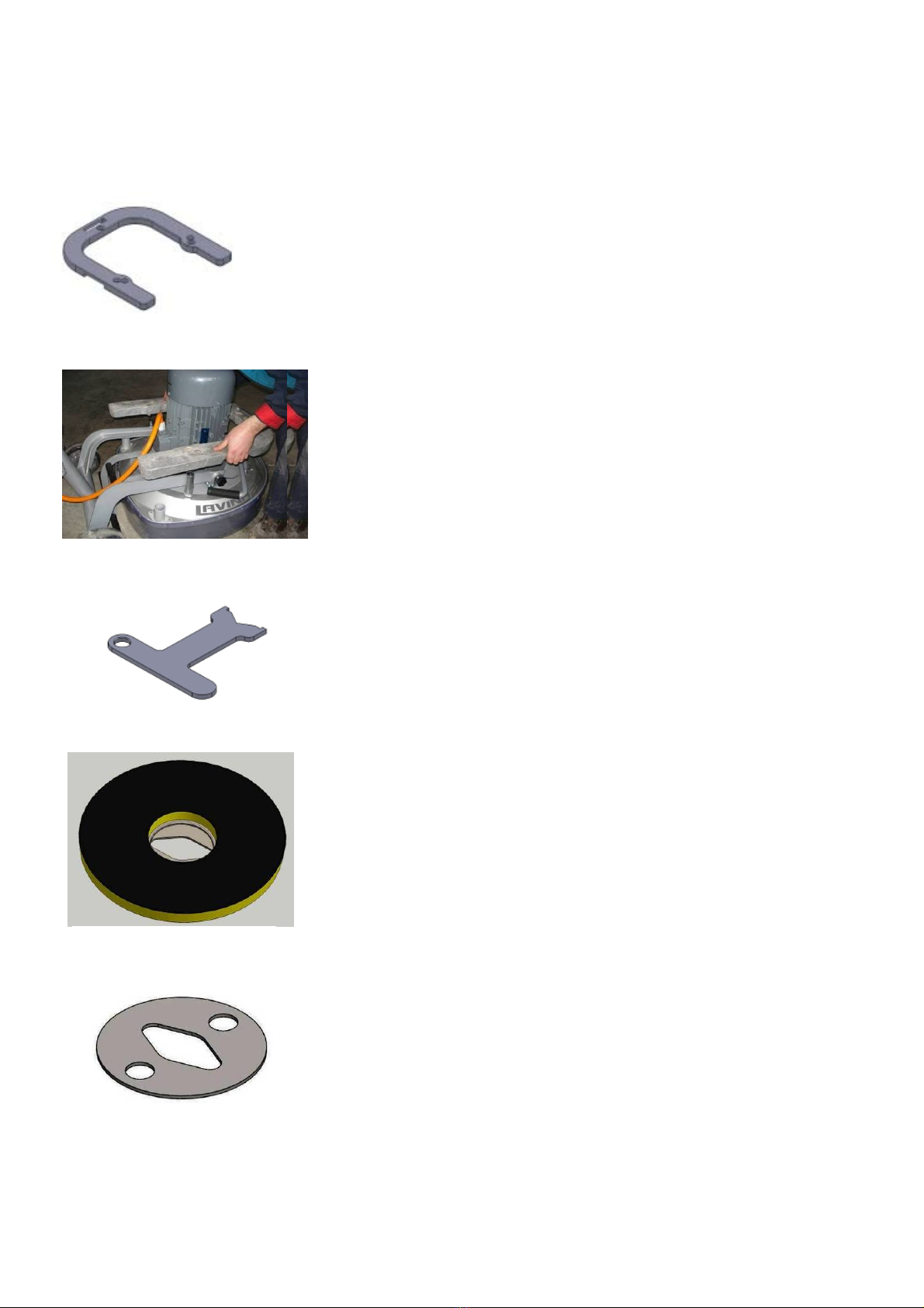
5.TOOLSANDACCESSORIES............................................................8
WEIGHTS.....................................................................................8
TOOLHOLDERKEY......................................................................8
FOAMPLATE...............................................................................8
SECURITYPLATEFORQUICKCHANGEPADS................................8
6.POPULARTOOLS..........................................................................9
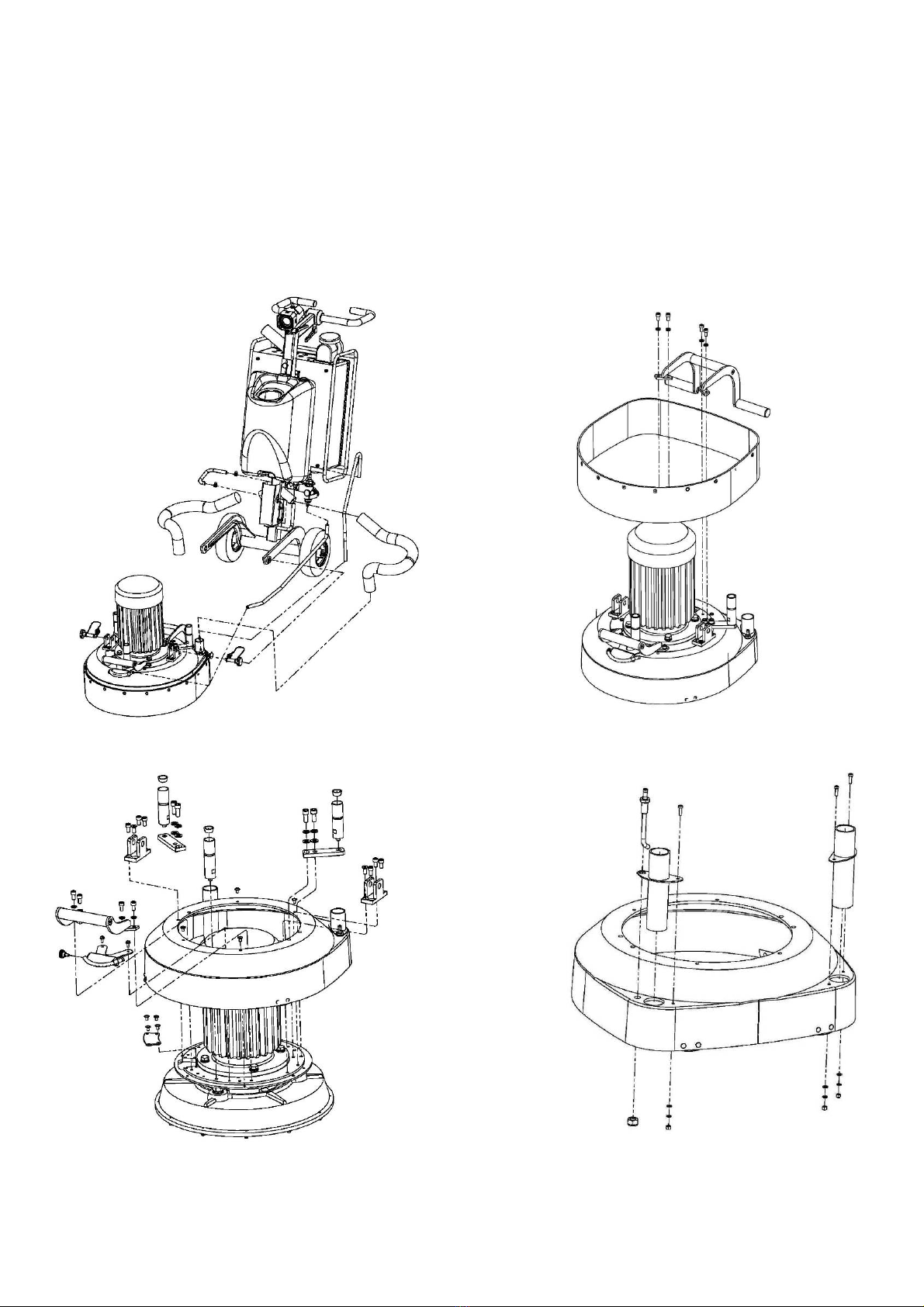
7.EXPLODEDVIEW.........................................................................10
GENERALEXPLODEDVIEW(FIG.7.1).........................................10
MAINHEADEXPLODEDVIEW(FIG.7.2).....................................10
TOPCOVEREXPLODEDVIEW1(FIG.7.3)...................................10
TOPCOVEREXPLODEDVIEW2(FIG.7.4)...................................10
BOTTOMCOVEREXPLODEDVIEW1(FIG.7.5)...........................11
PLANETARYDRIVEEXPLODEDVIEW(FIG.7.6)...........................11
BOTTOMCOVEREXPLODEDVIEW2(FIG.7.7)...........................11
PULLEYUNITSEXPLODEDVIEW(FIG.7.8).................................11
CARRIAGEEXPLODEDVIEW(FIG.7.9).......................................11
TOOLHOLDEREXPLODEDVIEW(FIG.7.10)...............................11
8.MAINTENANCEANDINSPECTION...............................................12
CLEANING.......................................................................................12
LAVINA®20N‐S‐OEELECTRICALSCHEMESWITHYASKAWA
INVERTER200‐240VOLT...........................................................11
LAVINA®20N‐S‐EELECTRICALSCHEMESWITHYASKAWA
INVERTER380VOLT..................................................................12
9.TROUBLESHOOTING...................................................................13
9.1REPLACINGPOWERCORDANDPLUGS...............................13
9.2DISMOUNTINGANDMOUNTINGTOOLHOLDERTOCHANGE
BUFFERSANDSPIDERS,CHANGINGV‐RINGSANDFELTRINGS..13
9.3TENSIONINGANDREPLACETHEPLANETARYBELT..............14
9.4TENSIONINGUSEDPLANETARYBELT..................................14
9.5MOUNTINGANDTENSIONINGANEWPLANETARYBELT....14
9.6REPLACINGPULLEYUNITS...................................................15
9.7MOUNTINGTHEBELT.........................................................17
9.8CHECKINGTHETENSIONOFTHEBELT................................18
9.9MOTORCONNECTION.........................................................18
9.10FAULTDIAGNOSISINVERTERYASKAWAV1000................19
10.WARRANTYANDRETURNS.......................................................22
WARRANTYPOLICYFORTHELAVINA®S‐EMACHINE...............22
RETURNPOLICYFORLAVINA®S‐EMACHINES..........................22
11.DISPOSAL..................................................................................22
12.MANUFACTURER’SCONTACTS.................................................22
13.SPAREPARTS............................................................................23
1.LAVINA®20N‐S‐EGENERALPARTS
FORMACHINESPRODUCEDBEFOREJAN.12014/....................23
1.LAVINA®20N‐S‐EGENERALPARTS
FORMACHINESPRODUCEDAFTERJAN.12014/......................23
2.LAVINA®20N‐S‐ETOPCOVERPARTS1................................24
3.LAVINA®20N‐S‐EGUARDPARTS.........................................24
4.LAVINA®20N‐S‐ETOPCOVERPARTS2................................24
5.LAVINA®20N‐S‐ETOPCOVERPARTS3................................25
6.LAVINA®20N‐S‐EBOTTOMCOVERPARTS1........................25
7.LAVINA®20N‐S‐EPLANETARYDRIVEPARTS........................25
8.LAVINA®20N‐S‐EBOTTOMCOVERPARTS2........................26
10LAVINA®20N‐S‐ETOOLHOLDERPARTS...............................27
11.LAVINA®20N‐S‐EWATERSUPPLYPARTS
FORMACHINESPRODUCEDBEFOREJAN.12014/...................27
11.LAVINA®20N‐S‐EWATERTANKPARTS
FORMACHINESPRODUCEDAFTERJAN.12014/....................27
12.LAVINA®20N‐S‐ECARRIAGEPARTS/FORMACHINES
PRODUCEDBEFOREJAN.12014/..............................................28
12.LAVINA®20N‐SCARRIAGEPARTS/FORMACHINES
PRODUCEDAFTERJAN.12014/................................................29
13.1LAVINA®20N‐S‐OECONTROLBOXPARTS200‐240VOLT.30
13.2LAVINA®20N‐S‐ECONTROLBOXPARTS380VOLT...........31

Superabrasive UserManual OriginalLanguage Lavina®20N‐S‐E/Lavina®20N‐S‐OE 8/2014
3
1.GENERALINFORMATION
Thisowner’smanualisintendedfortheoperatoroftheLavina®S‐Emachine,theservicingtechnicianaswellasforanyone
involvedwithoperatingorservicingthemachine.Werecommendthatyoureadtheinstructionsverycarefullyandfollowthem
strictly.
Themanualincludesinformationaboutassembling,using,handling,adjustingandmaintainingyourLavina®S‐Efloorgrinding
andpolishingmachine.
MANUFACTURER
Superabrasivewasfoundedin1987,asamanufacturerofhighqualitydiamondtoolsforthestoneandconcreteindustry.Today,
Superabrasiveisoneoftheworld’sleadingcompaniesintheproductionofdiamondtoolsandfloorgrindingmachinery.At
Superabrasive,westrivetodelivertheverybestsolutionstoourcustomers,andenablethemtoworkmoreefficiently.
GENERALDESCRIPTION
TheLavina®S‐Emachineisintendedforgrinding,polishingandbuffingconcrete,marble,granite,limestoneandterrazzosurfaces
withdiamondtools.
TheLavina®S‐Emachineisathree‐discmachine,whichcanbeuseddryaswellaswet.
Forbestresults,useonlytoolsmanufacturedorrecommendedbySuperabrasiveanditsdistributors.Additionally,themachine
couldbeusedforgrindingwoodfloorsurfaces.
TheLavina®S‐Emachineismanufacturedandfittedfortheabove‐
mentionedapplicationsonly!Everyotherusemaycauseriskstothepersonsinvolved.
MACHINECHARACTERISTICS
TheLavina®S‐Emachineismadeoftwomaincomponentsections:
MAINDESIGN
Thetwomaincomponentsectionsarethecarriageandmainhead.
Thehandle(Fig.1.2)ontheframeisadjustableinheightandallowstheoperatortowork
inacorrectandsafeworkingposture.
Thehalogenspotlight(Fig.1.2)enablestheoperatortoworkindarkerareas.
Existinglightingsystemdoesnotreplaceadequateoverhead
lighting.
Theframe
Thecontrolsarepositionedontopoftheelectricalbox(fig.1.3)
Theelectricalbox(fig.1.3)containstheelectricswitchingdevicesandthe
inverter.Themainfeedingcableisconnectedwithaplugandsocketontop.Themotor
feedingcableispluggedintothesocketlocatedonthebottomofthebox.Thetankison
theoppositesideoftheframe,sothattheweightofthewaterhasnoinfluenceonthe
operationofthemachine.Theframeweight,ontheotherhand,isfullyabsorbedbythe
drivingwheels.Anelectricpumpspraysthewaterthroughafrontsprayerorinternal.The
motorismountedonthebaseplateandisdrivingthethreeheadswithabeltsystem.The
planetaryheadisdrivenbyasecondflatbelt.
ENVIRONMENTALCONDITIONS
ThetemperaturerangeforoperatingtheLavina®S‐Emachineoutdoorsisbetween41°F
and
86°For5°Cand30°C.NeverusetheLavina®S‐Emachineduringrainorsnowwhen
workingoutdoors.Whenworkingindoors,alwaysoperatethemachineinwell‐ventilated
areas.
ELECTRICALCONNECTION
Thevoltage(Volt)andpower(Ampere)aredisplayedonalabelontheelectricalcontrol
boxtoavoidanyincorrectconnection.Refertothesebeforeconnectingthepower.To
avoidelectricalshocks,makesurethegroundpowersupplyisfunctioningproperly.
Figure 1.3
Fi
g
ure 1.1

Superabrasive UserManual OriginalLanguage Lavina®20N‐S‐E/Lavina®20N‐S‐OE 8/2014
4
VACUUMCONNECTION
Aconnectionforavacuumdustextractorislocatedonthecarriage.TheLavina®S‐Emachinedoesnotincludeavacuum
dustextractor.Thecustomermustpurchasethevacuumdustextractorseparately.Thehoseofthevacuumextractormust
beØ50.8mmandcanbeglidedoverthepipe.Thevacuumdustextractormustbeadaptedforfloorgrindersandhavea
minimumairdisplacementof320m3/hwithanegativevacuumof21kPa.
TECHNICALDATA
CE‐CERTIFICATION
TheLavina®S‐Emachineisdesignedtooperatecorrectlyinanelectromagneticatmosphereofindustrialtypeandisequippedwith
allthemechanicalandelectricalsafetyprotectionsinconformitywiththefollowingEuropeanCEErulesandregulations:
TheLavina®S‐EmachinecomplieswiththeSafetyDirectiveformachines2006/42/EC,theEMCDirective2004/108/ECandthe
LowVoltageDirective2006/95/EC.
AlsocomplieswiththenormsinuseBDSENISO12100,BDSEN13862,BDSENISO13857,BDSEN349,BDSENISO13850,BDSEN
13732‐1,BDSEN953,BDSENISO13849‐1,BDSEN1037,BDSENISO5349‐1,BDSENISO11201,BDSENISO3744,BDSEN
1033:2002,BDSEN60204‐1,BDSEN1837,BDSEN61000‐6‐4,BDSEN61000‐6‐2,BDSEN61000‐4‐2,BDSEN61000‐4‐4,BDSEN
61000‐4‐5,BDSEN61000‐4‐11,BDSEN55016‐2‐1
Testresultsareapartofthemachine’stechnicalinformationandcanbesentuponaspecialrequest.Themachineisdelivered
withtheCEmarkexposedandprovidedwithaECdeclarationofconformity.
VIBRATIONS
Themeasuredvibrationvalueonthesurfaceofgrippingincaseofguidingthemachineisahw=2.95m/s2.Themeasurementis
madeinaccordancewiththeBDSENISO1033andBDSENISO5349‐1.
SONOROUSEMISSIONS
Themaximumnoiselevelatdistanceofthemachineof1mincaseofworkingatidledoesnotexceed70dB(A).Themeasurementismadein
accordancewiththeBDSENISO11201andBDSENISO3744.
LABELDATA
ThedataonthelabelprovidesthecorrectVoltageandkW(neededforoperationalpurposes);
Weight(neededfortransportationpurposes);productionyearandserialnumber(neededformaintenancepurposes).
CUSTOMERSERVICE
ForcustomerassistanceandtechnicalsupportcontactyourlocaldistributororcontacttheproducerSuperabrasiveLtd.orvisitus
atwww.superabrasive.com,whereyoucandownloadacopyofthismanual.
2.SAFETYINSTRUCTIONS
RECOMMENDEDUSE
TheLavina®S‐Emachineis
designedandmanufacturedtogrindandpolishconcrete,
terrazzo,andnaturalstonefloors.Itcanbeusedforrenovations
aswellasforpolishing.Themachineisdesignedfordryorwet
use.Whenusingitdry,useavacuumofappropriatesize.For
moreinformation,pleaserefertothechapteronhandlingthe
vacuumconnection.
PROHIBITEDUSE
ThemachineMUSTNOTbeused:
ForapplicationsdifferentfromtheonesstatedintheGeneral
Lavina®20N‐S‐OE Lavina®20N‐S‐E
Voltage/Hz1phx200‐240V50‐60Hz 3phx380V50‐60Hz
AmperageMax15 Amps Max15Amps
Power5,5kW7,5HP 5,5kW7,5HP
Toolholderrpm300‐1100rpm 300‐1100rpm
Workingwidth510mm20” 510mm20”
Tooldiameter(QCPlate)3x225mm3x9” 3x225mm3x9”
Weight167kg368lbs 167kg368lbs
Grindingpressure80kg177lbs 80kg177lbs
Additionalweightmax2x22kgmax2x48 lbs max2x22kgmax2x48 lbs
Applicationwetanddry wetanddry
VacuumhoseportYes Yes
Watertankcapacity20l5.2gal 20 l5.2gal
Waterfeedwithpump(peripheralandfront) withpump(peripheralandfront)
Cablelength17.4m57ft 17.4m57ft
MachineLxWxH1350x540x1100mm53.1”x21.3”x43.3” 1350x540x1100mm53.1”x21.3”x43.3”
PackingLxWxH1150x730x1155mm45.2”x28.7”x45.5” 1150x730x1155mm45.2”x28.7”x45.5”

Superabrasive UserManual OriginalLanguage Lavina®20N‐S‐E/Lavina®20N‐S‐OE 8/2014
5
Descriptionchapter.
Fornot‐suitablematerials.
Inenvironmentswhich:Possessrisksofexplosion
Possesshighconcentrationofpowdersoroilsubstancesintheair
Possessrisksoffire
Featureinclementconditions.Possesselectromagneticradiation.
PREPARATIONFORWORK
MakesurethatYouhaveclosed
theworkarea,sothatnopersonunfamiliarwithoperatingthe
machinecanenterthearea.Thetoolplateandtoolsareadjustedto
themachineproperly.Therearenomissingpartsofthemachine.
Themachineisinuprightworkingposition.Theprotection
devicesareworkingproperly.Theelectricalcableisfreemove
andfollowthemachineeasily.Inordertokeeptheelectrical
cablefrombeingdamaged,novehicleshouldcrossthezone
whereelectricalcablesaresituated.
PROTECTIONDEVICES
Themachineisequippedwith
severalprotectiondevicesincludingthefollowing:
Anemergencystopbutton
Aprotectionskirtandhoodforprotectingthetoolplates.
Thesedevicesprotecttheoperatorand/orotherpersonsfrom
potentialinjuries.Donotremovethem.Oncontrary,before
usingthemachine,pleaseensurethatallprotectiondevicesare
mountedandfunctionproperly.TheSecurityplatepreventsthe
QuickChangepadsfromlooseningduringuse.
ARRESTFUNCTIONS
Functionsofarrestingthe
machinearefollowing:Buttontostopthemotor
(category1)
Emergencybutton(category1)
SAFEUSE
TheLavina®S‐Eisdesignedto
eliminateallriskscorrelatedwithitsuse.However,itisnot
possibletoeliminatetherisksofaneventualaccidentwiththe
machine.Unskilledoruninstructedoperatormaycause
correlatedresidualrisks.Suchrisksare:
PositionRisksduetooperator’sincorrectworkingposition
TanglingupRisksduetowearinginappropriateworkingclothes
TrainingRisksduetolackofoperationaltraining
NOTE:Inordertoreduceallconsequencesoftheabove‐
mentionedrisks,weadvisethatmachineoperatorsfollowthe
instructionsinthemanualatalltimes.
RESIDUALRISKS
Duringthenormaloperating
andmaintenancecycles,theoperatorisexposedtofewresidual
risks,whichcannotbeeliminatedduetothenatureofthe
operations.
BEFOREYOUBEGIN
Workingareamustbeclear
fromanydebrisorobjects.
Afirst‐timeoperatormustalwaysreadthemanualandpay
attentiontoallsafetyinstructions.
Allelectricconnectionsandcablesmustbeinspectedfor
potentialdamages.
Groundwiresystemofthepowersupplymustbealsoinspected.
Performgeneraldailyinspectionsofthemachineandinspect
themachinebeforeeachuse.
Alwaysinspectthesafetydevices:MounttheSecurityplatefor
theQuickchangepads.
Theemergencybreakmustbeclearandworking
Thetoolprotectormustbeworking
Themachinemustbeclean
Neveroperatethemachineintherain!
Confirmthattherearenomissingpartsespeciallyafter
transportation,repair,ormaintenance.
Beforefillingthewatertankwithwatermakesurethemachine
isnotworkingandthemainswitchisturnedoff.
Beforeturningonthemachinemakesurethatthebaseisplaced
onthefloor,themachineMUSTNOTbeinanupright
positionwhenturnedon!
OPERATINGMACHINE
WhenoperatingtheLavina®S‐E,makecertainthatthereis
noone,butyouaroundthemachine.
Neverleavethemachineunattendedwhileworking.
Theelectricalcablemustmovefreelyandmustbedamage‐free.
Thewaterhosemustmovefreelyandmustbedamage‐free.
Checktheflooryouwillworkontomakesureitisnottoo
uneven.Ifthisisthecase,itmaydamagethemachine.
AFTERWORKISCOMPLETED
Cleanthemachineandits
surroundingsproperly
Emptyandcleanthewatertank
Unplugthemachineandwinduptheelectricalcable
Storethemachineinasafeplace
THEWORKAREA
Makecertainthatpeopleor
vehiclesdonotentertheworkarea.
Avoidcablesandhosesbeingintheway.
Alwayscheckthefloorfordebris
PERSONALPROTECTIVE
EQUIPMENT(PPE)
Alwayswearsafetyshoeswhenworkingwiththemachine.
Alwayswearearprotectors
whenworkingwiththe
machine.
Allpersonnelintheimmediateworkareamustwearsafety
glasseswithsideshields.
Alwayswearsafetygloveswhenchangingthetools.
Alwayswearclothessuitablefortheworkenvironment.
OPERATOR
TheLavina®S‐Emachine.
Theoperatormustknowthemachine’sworkenvironment.
Onlyoneoperatoratatimecanworkwiththemachine.
Theoperatormustbeproperlytrainedandwellinstructed
prioroperatingthemachine.
Theoperatormustunderstandalltheinstructionsinthis
manual.
Theoperatormustunderstandandinterpretallthedrawings
anddesignsinmanual.
Theoperatormustknowallsanitationandsafetyregulations
pertainingtotheoperationofthemachine.
Theoperatormusthavefloorgrindingexperience.
Theoperatormustknowwhattodoincaseofemergency.
Theoperatormusthaveanadequatetechnicalknowledgeand
preparation.

Superabrasive UserManual OriginalLanguage Lavina®20N‐S‐E/Lavina®20N‐S‐OE 8/2014
6
3.HANDLINGANDTRANSPORTATION
PREPARINGTHEMACHINEFORTRANSPORTATION
Unplugthemotorcableplugfromthecontrolbox(Fig.3.1)anddisconnectthewaterhosefromthemainheadbypullingitout
(Fig.3.2).Windtheelectricalcableonthecarriage.Releasethepinsets(Fig.3.3)whichattachtheheadtothecarriage.
Pulloutthevacuumhoses,anddismountthehead
fromthecarriage(Fig.3.4).
TheheadoftheLavina®S‐Emachinehasone
barandasupportusedashandlesintendedforeasy
movingandtransportation(Fig.3.4).TheLavina®S‐E
machineisengineeredwitheasytransportationin
mind.Theabilityto
dismantlethemachineintwopartsallowsconvenient
transportationandstorage(Fig.3.4,Fig.3.5).
STORAGE
AlwaysstoreandtransporttheLavina®S‐Emachineinadryplace.NevertransporttheLavina®S‐Emachineunprotected;it
maybedamagediftransportedunprotectedduringrainorsnow.
Whenstoringthemachinethetemperaturemayfalltoorlessthan32F(0°C),therefore,youshouldemptythewaterfromthe
systemusingfollowingsteps:
‐ Pulloutthehoseofthetank(Fig.3.6)
‐ Usingcompressedairblowoutthewaterfromthesystemforthetwopositionsoftheturn‐cock(Fig.3.7,Fig.3.8).
4.OPERATION
PRELIMINARYCONTROLS
Inspecttheworkingareaasexplainedinthesafety
instructions.Forwetuse,fillinthewatertankwhen
theelectricalcableisdisconnected.Connectthe
vacuumextractorandensurethatthevacuumhoseis
clearanditwillfollowthemachineeasily.Pluginthe
machineandmakesurethatthepowercordisfreeto
followtheworkingdirectionoftheLavina®S‐Emachine.
WATERFLOWCONTROLUNIT
Theoperatorcanchoosethewaterspraysinthefront(Fig.4.1)whenthelevelofthetapisinthehorizontalposition(Fig.4.2),when
thelevelisintheverticalposition(Fig.4.2)waterwillsprayundercoverofthemachine.
Theflowregulatingvalvelocatedonthetank(fig.4.2.1)isincreasingorreducingthewaterflowtotheworkingarea–infrontofthe
machineorunderthemainheadcoverofthemachine/onlyformachinesproducedafterJan.12014/.
Fi
g
ure 3.4 Fi
g
ure 3.5
Fi
g
ure 3.1 Figure 3.3
Fi
g
ure 3.2
Figure 3.6 Figure 3.7 Figure 3.8
Fi
g
ure 4.2.1
Figure 4.1 Figure 4.2

Superabrasive UserManual OriginalLanguage Lavina®20N‐S‐E/Lavina®20N‐S‐OE 8/2014
7
ADJUSTINGANDMOUNTINGTOOLS
Mountthetoolsonlyafterensuringthatthereisenoughdiamondbondmaterialleft.Besurethattheplatesarealways
cleanbeforemounting.(Fig.4.3)
WARNING:Alwayssecurethe“Quickchange”padswiththesecurityplate(Fig.4.4),andlockwiththetoolholderkey
(Fig.5.4).DiamondtoolswithVelcroareattachedonthree9inchfoamplates.Thefoamplatesaremountedonthekey
lock(butterfly).Alwaysusethetoolholderkey(Fig.5.4).
THECONTROLBOARD
1. Powercableplug
2. DigitalRPMindicatorIndicatestherevolutionper
minuteofthegrindingplates(nottherevolutionper
minuteoftheentireunit).
3. Lampcablegland
4. InverteralarmledLightsbluewhentheinverter
goesintoalarmmode.
5. WaterpumpswitchLightsorangewhenthewater
pumpisworking.
6. Powerledlightsgreenwhenthepowerison
7. Forward/Reverseswitchchooseforwardfor
clockwiserotationofthegrindingplatesorreverse
foranti‐clockwiserotationofthegrindingplates
8. PotentiometerchangestheRPMofthegrinding
platesfrom300‐1100rpm
9. Resetbuttonresetsthealarmoftheinverter
10. OFFbuttonstopsthemotor
11. ONbuttonstartsthemotor
12. EmergencybuttonusedinEmergencysituationsfor
stoppingthemotor
STARTINGTHEMACHINE
First,followthedirectionsinchapterSafetyDevicesandSafetyInstructions.Next,pulltheemergencystop(12)toensurethat
themachineisinworkingcondition.Checkthepotentiometer(8)andensurethatitissetattheworkingspeed.Ifworkingwet,
addwatertothefloorsurface.Ifworkingdry,omitthisstep,andinstead,switchonthevacuumunit.Finally,holdthemachine
firmlyandpushthestartbutton(11).
OPERATINGTHEMACHINE
Guidethemachineinstraightlinesacrossthefloor,andwitheachnewlineoverlapalittlebitofthepreviouslycompleted
surface.Workataconstantspeedallowingthetoolstimetoworkataspeedappropriateforthetools’gritsize.Avoidvibrations.
DonotstoptheLavina®S‐Emachineinonespotwhilethetoolsarestillworkingbecausetheywillleavemarksonthefloor
surface.Whenworkingwet,firstchoosethewatertapposition(Fig4.2)forwaterfeedandperiodicallystartthepumptorelease
waterontothefloor’ssurface(Fig.4.6Pos.5).Whenworkingdry,checkthefloorsurfaceperiodicallytoensurethatdustisnot
accumulatingonthesurface,alsocheckregularlyifyourvacuumworksproperly.
STOPPINGTHEMACHINE
Thestoppingofthemachinemustbedonegraduallyuntilthemotorstops.Donotstopmovingthemachinebeforearrestingthe
motorasthetoolscoulddamagethesurface.Tostoppushtheoffbutton(10).UsetheEmergencybutton(13)onlyin
emergencyoruseittoswitchthepowertotallyoff.Remembernottoholdthemachineinonespotbeforeturningoffthe
motor.
ALARM
TheAlarmlight(4)willlightincaseinvertergoesinalarmmode.Themostcommonfailureismotorinoverload.Toresetthe
modepushresetbutton(9).
Figure 4.3 Figure 4.5
Fi
g
ure 4.4
Figure 4.6
1234567
89101112

Superabrasive UserManual OriginalLanguage Lavina®20N‐S‐E/Lavina®20N‐S‐OE 8/2014
8
5.TOOLSANDACCESSORIES
WEIGHTS
Superabrasiveoffersadditionalweightsforincreasingtheproductivityofthemachine(Fig.5.1).
Eachadditionalweightweighsabout48lbsor22kg.Eachindividualapplication,typeand
conditionofsurface,powercapacityoftheoutlet,etc.willdeterminethenumberofweights
youcanusewithout
trippingabreaker.Theweightstacksontothreepostsaroundtheouterbowl(Fig.5.2).
Theadditionalweightsdependonthetools;itisnotalwayspossibletoaddweights.Some
toolsworktooaggressivelyandthemachinecanstop.Theweightcanbeorderedwithitem
numberA07.00.00.00.
TOOLHOLDERKEY
Thetoolholderkey(Fig.5.3)isusedforadjusting,mountinganddismountingofthefoam
plates.Alwaysusethekeyfor
mounting.Itemnumberis
A03.00.00.00
FOAMPLATE
DiamondtoolswithVelcroaremountedonthefoamplate9“(Fig.5.4).Thefoam
plateismountedonthe“QuickChange”System.
ItemnumberisLV‐9‐FP‐S
SECURITYPLATEFORQUICKCHANGEPADS
Plateusedtoensurethe“Quickchange”pads.
ItemnumberisA38.00.01
Figure 5.3
Figure 5.1
Fi
g
ure 5.2
Figure 5.4
Figure 5.5

Superabrasive UserManual OriginalLanguage Lavina®20N‐S‐E/Lavina®20N‐S‐OE 8/2014
9
6.POPULARTOOLS
RECOMMENDEDTOOLS
QuickChange System and Tooling feature extremely fast and convenient tool changes, and a
long tool
life, providing for great long‐term cost savings. The QuickChange pads are produced in
four different
bonds for super hard, hard, medium and soft concrete, in a variety of grit sizes.
They are offered with
1 or 2 buttons or rectangular segments, which allows you to customize the aggressiveness of
the cut.
cut.
Calibragrindingdiscs:ourpopularceramicbonddiscsaredesignedfortheremovalofdifficultscratches
and
theysaveyouvaluabletimebyeliminatingtheneedformultiplepasseswithmetaltools.Theycanbe
usedwetordry,andarebestforhardconcreteapplications.
Theyare3‐inch,withincludedVelcrobackattachment.
NATO®polishingdiscsfeatureaspecialresinformuladesignedforbothwetanddryapplicationsandauniquedesignwith
widechannelsallowingforworkonacleanersurfaceandensuringaqualitypolish.Availablein3and4insizes.Theyare
with
includedVelcroattachment.
V‐HARR®PremiumPolishingPadsaredesignedformechanicallypolishingandrestoringconcrete;alsoidealforterrazzo
and
hardstonefloors.V‐HARR®padsareofferedinawidevarietyofdiametersandgritsizestoaccommodatemany
applications.
Dryuseisstronglyrecommended.
ShinePro®arehighqualitydiamond‐impregnatedpadsforfloormaintenance.Availableinavarietyofsizes,andaregreatfor
dailyuse.Whenusedwet,theyrequireonlywater(nowaxorchemicalsneeded)andareaveryenvironmentallyfriendly
solution
formaintainingfloors.
UseonlySuperabrasive’srecommendedtools.Formoretoolingoptions,visitwww.superabrasive.com

Superabrasive UserManual OriginalLanguage Lavina®20N‐S‐E/Lavina®20N‐S‐OE 8/2014
10
7.EXPLODEDVIEW
GENERALEXPLODEDVIEW(FIG.7.1)
MAINHEADEXPLODEDVIEW(FIG.7.2)
TOPCOVEREXPLODEDVIEW1(FIG.7.3)
TOPCOVEREXPLODEDVIEW2(FIG.7.4)
Figure 7.3
Figure 7.4
Figure 7.1 Figure 7.2

Superabrasive UserManual OriginalLanguage Lavina®20N‐S‐E/Lavina®20N‐S‐OE 8/2014
11
BOTTOMCOVEREXPLODEDVIEW1(FIG.7.5)
PLANETARYDRIVEEXPLODEDVIEW(FIG.7.6)
BOTTOMCOVEREXPLODEDVIEW2(FIG.7.7)
PULLEYUNITSEXPLODEDVIEW(FIG.7.8)
CARRIAGEEXPLODEDVIEW(FIG.7.9)
TOOLHOLDEREXPLODEDVIEW(FIG.7.10)
Figure 7.9
Figure 7.8
Figure 7.10
Figure 7.6
Figure 7.7
Figure 7.5

Superabrasive UserManual OriginalLanguage Lavina®20N‐S‐E/Lavina®20N‐S‐OE 8/2014
12
8.MAINTENANCEANDINSPECTION
Cleaning
Keepyourmachineclean.Cleaningthemachineonaregularbasiswillhelpdetectandsolvepotentialproblemsbeforetheycause
damagetothemachine.Mostimportantly,checkandcleanthetoolplateconnections,powercordandplugs,vacuumhosesand
watertank.
Figure 8.1
CHECKDAILY
AfteroperatingtheLavina®S‐Emachine,theoperatorshouldconductavisualinspection
ofthemachine.Anydefectshouldbesolvedimmediately.Payattentiontopowercords,
plugsandvacuumhoses,looseboltorscrews.
Toolholders:Buffersandspidersareconsumablesandmustbevisuallycheckeddailyand
replacedifneeded.Seethatflangesordiscsaremountedandlockedwellinplace.The
keylockholders(butterflies)shouldbealsochecked.
Checktherubberbuffersandfixingoftheholders.Theflangeholdingthebuffers(Fig.8.1
1)hastobefirmlyfixedtotheunit.Agapseentheremeansthatthereareloosescrews
fixingtheholder.Thescrewshavetobetightenedimmediatelyforsafeoperation.
Workingwithloosescrewsontheholdercouldalsocausebaddamagesonthemachine.
Tighteningforceofthescrewshastobe25...30N.m(18...22ft/lbs).
Itisveryimportanttoregularlycheckthescrews(Fig.8.12)thatfixthe
"Quickchange"holdertothesafetypart,sothattheholderwillnotflyawayifthebuffers
getdamaged.
“Quickchange”shouldbeclean.Thetensionoftheplanetarybeltcanbecheckeddailybymovingthemainheadandfeelingthe
resistanceofthemovingpulleys,ifthebeltslipstensionimmediately,seethechapterTroubleshooting.
CHECKANDREPLACEAFTERTHEFIRST15WORKINGHOURS
Checkthebelttensionafter15hoursworkingwiththemachine.
Thebottomcoverhasacontrolcover(Fig.8.2)thatallowsfastandeasycontrolandcorrection
ofthebelt.Itisrecommendedtocheckthetensionofthebeltafterthefirst15hoursandto
tightenifnecessary.Forthecorrecttension,seeTROUBLESHOOTING“mountingthebelt”.
Everytimeyouopenthecontrolcover,mountbackallthescrews.
CHECKEVERY200WORKINGHOURS
Every200workinghours,theoperatorshouldinspectallpartsofthemachinecarefully.Most
importantly,inspectandcleanthetoolplateconnections,powercordandplugs,vacuumhoses
andwatertank,andfilter.Also,checkthewaterflowofthepump.Checktheguard
Figure 8.2
assembly.Makecertainthewheelsarecleanandrotateproperly.Inspectthecontrolbuttons.Iftherearedefectivecontrolparts,
theyshouldbereplacedimmediately.Replacewornvacuum‐andwaterhoses.Checkthetensionofthebeltandtotightenif
necessary.Forthecorrecttension,seeTROUBLESHOOTING.
Dismountthetoolholders(SeeTroubleshooting)replaceallparts(Spider,buffers,sealercaps,“O”rings)withtheslightest
damageorconsume.
Opentheinspectioncoveronthemotorbasetochecktheplanetarydrivingbelt,bymovingthemainheadthebeltshouldnotslip
ontheplanetarypulleyanddrivethepulleys.
CHECKEVERY400WORKINGHOURS
Besidesthechecksof200workinghours,replacesealerandV‐ringslikedescribedinchapter“TROUBLESHOOTINGREPLACING
BELTANDPULLEYUNITS”.Checkifbeltsandbearingsareingoodcondition,changeifneeded.
VACUUM
Asstatedpreviously,frequentlycheckhosesandotherpartsforclogging.
WATERLEAKS
Replaceanyleakingpartsimmediatelyasthewatercoulddamageyourmachine
MECHANICALPARTS
Partssuchasthebelts,sealrings,caprings,spidersandbuffersandguardassemblyaresubjecttowearandshouldbereplacedas
needed.
ELECTRICALSYSTEM
Dustshouldnotenterthecontrolbox,asitwilldestroythecontacts.Remove(blowout)anydustpresent.

Superabrasive UserManual OriginalLanguage Lavina®20N‐S‐E/Lavina®20N‐S‐OE 8/2014
11
LAVINA®20N‐S‐OEELECTRICALSCHEMESWITHYASKAWAINVERTER200‐240VOLT
200‐240Volt
Figure 8.7
Themotorisconnectedin“Delta”
(triangle)230Volt,
reminderforthewireconnectionof
themotor.
Figure 8.5
Figure 8.6
Figure 8.4

Superabrasive UserManual OriginalLanguage Lavina®20N‐S‐E/Lavina®20N‐S‐OE 8/2014
12
LAVINA®20N‐S‐EELECTRICALSCHEMESWITHYASKAWAINVERTER380VOLT
LAVINA® 20N-S-E ELECTRICAL SCHEMES YASKAWA
CONNECTION MAIN CIRCUIT TERMINALS
Themotorisconnectedin
“Star”380Volt,
reminderforthewire
connectionofthemotor
Figure 8.11
Figure 8.9
Figure 8.10
Figure 8.8

Superabrasive UserManual OriginalLanguage Lavina®20N‐S‐E/Lavina®20N‐S‐OE 8/2014
13
Figure 9.2.7 Figure 9.2.8 Figure 9.2.9 Figure 9.2.10
Figure 9.2.11
9.TROUBLESHOOTING
9.1REPLACINGPOWERCORDANDPLUGS
Whenreplacingthepowercordorplugsalwaysusecordsandplugswithspecificationsastheoriginalones.
Neveruselowerqualityordifferenttypecordandplugs.
Inaddition,takeintoconsiderationthedistanceoftheappliancefromtheelectricalsource.Thegreaterthedistance,thegreater
theresistanceandthelesscurrentthatwillbeavailableattheotherend;therewillbeavoltagedropandtheinverterwillsign
alarmmode.Thiscanalsohappenifseveralmachinesareworkingonthesamelineorwhenthegeneratorisunderrated.Ingeneral
ourstandardpowercablecanbedoubledinlength;iflongerlengthsareneededyouhavetoreplaceallthecableswithbiggergage
ratedcablesforthelengthandamperage.
9.2DISMOUNTINGANDMOUNTINGTOOLHOLDERTOCHANGEBUFFERSANDSPIDERS,CHANGINGV‐RINGSANDFELTRINGS
Tocheckorreplacethebuffersandthespiders,thetoolholdershavetobedismounted.Removethecountersunkscrewsontopof
thebuffer(Fig.9.2.1).Takethediscoff(Fig.9.2.2),thespidercanberemovedorreplaced(Fig.9.2.3).BylooseningfourHexcap
bolts(Fig.9.2.4),thedisccomesloose(Fig.9.2.5)andthebufferscanbereplaced(Fig.9.2.6).Attention,bymountingusealwaysthe
“blue”threadlockingadhesive,exceptontheboltstolockthebuffers(Fig.9.2.5).Alwaysusetheoriginalbolts.
Dependingonthenumber(3,4or6)ofbuffers,theholdercanbemoreflexibleorrigid.
Whenthetoolholderisdismounted,youcanchangethesealers(V‐RingandFelt‐Ring).
TakeoutFelt‐Ring,AdaptorandV‐Ring.Beforemountingcheckonwhichsidetheadaptoris
fitting,rememberthecorrectside.MounttheV‐RingwiththesmallestlipoftheVtoinside
(Fig.9.2.7)justpushtheV‐ringsothetopisonthesamelevelasthepulleytop(Fig.9.2.8).Then
taketheadaptorinthecorrectwayandpushtheV‐Ringdownwiththeadaptor(Fig.9.2.9).The
lowestlipoftheV‐Ringshouldonlybarelytouchitsglidingsurface;alsoneverpushtheV‐Ring
downwithfingers.MountnowtheFelt‐ringontop(Fig.9.2.10).Closethesealerswiththecap
(Fig.9.2.11).
Figure 9.2.1 Figure 9.2.2 Figure 9.2.3
Figure 9.2.4 Figure 9.2.5 Figure 9.2.6

Superabrasive UserManual OriginalLanguage Lavina®20N‐S‐E/Lavina®20N‐S‐OE 8/2014
14
9.3 TENSIONINGANDREPLACETHEPLANETARYBELT
Ifthebeltslipsorisbrokenseparatethecarriagefrommainhead,pulloutmotorplug(Fig.9.3.1),water‐(Fig.9.3.2)(Fig.9.3.3)
andvacuumtubes.Takeoffhandles,forksandweightholderssoyoucandismountthetopcover(Fig.9.3.4)(Fig.9.3.5)
9.4TENSIONINGUSEDPLANETARYBELT
Noticingspeedlostinplanetarymovementitispossibletotensionthebeltforplanetarymovementasdescribedin
9.5Mountingandtensioninganewplanetarybelt.
9.5MOUNTINGANDTENSIONINGANEWPLANETARYBELT
Figure 9.3.1 Figure 9.3.2 Figure 9.3.3 Figure 9.3.4 Figure 9.3.5
Figure 9.4.1 Figure 9.4.2
Figure 9.5.1 Figure 9.5.2 Figure 9.5.3
Figure 9.5.6
Figure 9.5.4 Figure 9.5.5
Figure 9.5.7 Figure 9.5.8 Figure 9.5.9

Superabrasive UserManual OriginalLanguage Lavina®20N‐S‐E/Lavina®20N‐S‐OE 8/2014
15
Completelydismountthetensioningdevice(Fig.9.5.1).Make2signsonthedismountedbelt
exactly10cmoutofeachother(beltwithouttension)(Fig.9.5.2).Thepurposeistomeasure10.2
cmonthebeltintensionwhatisatensionof2%.,amaximumof2.5%isallowed.
ATTENTION:NEVER“OVER”TENSIONTHEBELT,THEBELTWILLBEDAMAGEDANDITWILL
NEVERRECOVERITSORIGINALTENSION
Mountthebeltbackaroundtheplanetarypulley;seethatthebeltisbehindthedrivingpulley
(Fig.9.5.3).Putthebeltaroundtheleftrollerofthetensioningdevice(Fig.9.5.4).Putthe
tensioningdevicebackinplaceandpullthebeltfromtherollerontherightside(Fig.9.5.5).Put
thebeltaroundthedrivingpulley(Fig.9.5.6).Begintotensionuntilthemeasureof10cmbetween
themarksbecomes10.2cm
(Fig.9.5.7)(Fig.9.5.8).Tightenthetensioningdevicewhileturningtheboltmovetheplanetaryheadsothebeltcanslide.(Fig.
9.5.8).Donotforgettolockthetensioningdevice(Fig.9.5.9).
9.6REPLACINGPULLEYUNITS
Seepreviouschapterstotakeofthetoolholdersandtopcover.Unscrewthescrewsofthebottomcover(Fig.
9.6.1).Setthebottomcoverassemblyaside(Fig.9.6.2).RemovetheO‐ringstoavoidlosingthem(Fig.9.6.3).
Onlythetwoloose(non‐driving)pulleyscanberemovewithoutremovingontopthemotorbasediscandmotor.Loosethenut
ontopofthepulley(Fig.9.6.4).Carefullypullouttheunitwithcrowbars,butdonotuseexcessiveforce(Fig.9.6.5)(Fig.9.6.6).
Ifallthepulleyunitshavetobereplaced,dismountmotorbasediscandmotor.Beforeremovingthebeltunscrewthe
centralpulley(soitdoesnotturnwhileunlocking)(Fig.9.6.7)(Fig.9.6.8).Pullthecentralpulleyoff(Fig.9.6.9).
Figure 9.5.10
Figure 9.6.1 Figure 9.6.3Figure 9.6.2
Figure 9.6.4 Figure 9.6.6Figure 9.6.5
Figure 9.6.7 Figure 9.6.9Figure 9.6.8

Superabrasive UserManual OriginalLanguage Lavina®20N‐S‐E/Lavina®20N‐S‐OE 8/2014
16
Unlockbolts(Fig.9.6.10)andtakemoreoff(Fig.9.6.11).Unlockretainingshaft/bearing(Fig.9.6.12).Takeawaythefillingring
(Fig.9.6.13).Nowthemotorbasediscisunlocked,theonlywaytodismountitistopressitoutonabearingpress(Fig.9.6.14)
(Fig.9.6.15).Dismountingthedrivingpulley:takethetopscrewouttoreleasethebushing(Fig.9.6.16),pushthebushingtogether
withthewasherup(Fig.9.6.17),pushwasherdownofthebushing.,takebushingout(Fig.9.6.18),pushkeyout(Fig.9.6.19),nowthe
washerreleases(Fig.9.6.20),dismountsealercap(Fig.9.6.21),thepulleycanbereleasedwithtwocrowbars;donotuseexcessive
force(Fig.9.6.22)(Fig.9.6.23),pushthesealercaptodismount(Fig.9.6.24),bymountingbackthesealercap,securewithsealant,
centertheholestomountthepulley.
Figure 9.6.10 Figure 9.6.12Figure 9.6.11
Figure 9.6.13 Figure 9.6.15Figure 9.6.14
Figure 9.6.16 Figure 9.6.18Figure 9.6.17
Figure 9.6.19 Figure 9.6.21Figure 9.6.20
Figure 9.6.22 Figure 9.6.24Figure 9.6.23

Superabrasive UserManual OriginalLanguage Lavina®20N‐S‐E/Lavina®20N‐S‐OE 8/2014
17
Changethetwootherpulleysasearlierdescribedinthechapter,bestwhenthemotorbasediscisdismounttochangetheroller
unitstoo.Unlockthenutontop(Fig.9.6.25).Thepulleyscanbereleasedwithtwocrowbars;donotuseexcessiveforce
(Fig.9.6.26)(Fig.9.6.27).
9.7MOUNTINGTHEBELT
ThemountingofthebeltisshownonFig.9.7.11.Puttingthebelt
ispossiblewhenthetensionerisinstartingposition:
‐loosenthenutspos.2
‐loosenenoughthenutspos.3(orunscrewthem).
‐unscrewthenut(pos.4)andpulloutthebush(pos.5)fromhole
Dinthetensioner(pos.1),thatwillallowthetensionertohavethe
positioninFig.9.7.11.
‐putthebeltfollowingstepsshownonFig.9.7.2;Fig.9.7.3and
Fig.9.7.4.(Itispossiblealsotoputthebeltonthe rollerunitassemblyas
alaststep.)Checkifthebeltisontherightplaceinthegroovesofeachof
thepulleyunits andonthecentralpulley.
Putbackthetensionerinapositiontheaxlebushingtofitinthe
tensionerhole(Fig.9.7.5)(Youcanpushdownthebushscrewingthenut
pos.4)
Tightenthenuts(pos.2,Fig.9.7.1)onthesectorsandunscrew
halfrev.(Fig.9.7.5)Thiswillallowthetensionerturninminimum
clearance.Fastlightthebelt(Fig.9.7.7)inordertoachievetheright
positionandthentightenthenutinthecenterofthetensioner(Fig.9.7.6).Fastupthebelttakingcareofthetensioning(Fig.9.7.7).
ItisrecommendedthatthetensioningofthebeltbemeasuredwithOptikrikIIDevice(Measuringrange:500‐1400N)(Fig.9.7.8).
Foranewbeltthetensioningforceis650N,andthefasteningforceis520N.
Figure 9.6.25 Figure 9.6.27Figure 9.6.26
Figure 9.7.2 Figure 9.7.3 Figure 9.7.4
Figure 9.7.9
Fi
g
ure 9.7.1 Figure 9.7.5
Figure 9.7.6 Figure 9.7.7 Figure 9.7.8
Figure 9.7.11

Superabrasive UserManual OriginalLanguage Lavina®20N‐S‐E/Lavina®20N‐S‐OE 8/2014
18
ATTENTION:NEVER“OVER”TENSIONTHEBELT,THEBELTWILLBEDAMAGEDANDITWILLNEVERRECOVERITSORIGINALTENSION
Tightenthetwonutsonthesectorsandcontranutonthetensioner(Fig.9.7.10).Putthesealringonthebottomcoverandclose
themachine(Fig.9.7.11).
Reassembleinthesamemanner.
YourLavina®Smachineisnowreadyforuse!
9.8CHECKINGTHETENSIONOFTHEBELT
Openthecheckingcovertoreachthebeltandtensiondevice(Fig.9.8.1).Whiletensioningcheckregularlytension.Itis
recommendedthatthetensioningofthebeltbemeasuredwithOptikrikIIDevice(Measuringrange:500‐1400N)(Fig.9.8.2).
Fasteningforceis520N.
ATTENTION:
NEVER“OVER”TENSIONTHEBELT,THEBELTWILLBEDESTROYEDANDITWILLNEVERRECOVERITSORIGINALTENSIONLoose
thecontranuts(Fig.9.8.3),looselightthetwonutsofthetensiondevice(Fig.9.8.4),andadjustthetensionwiththenutseenin.
Whentherighttensionisreached:closethecontranutsandthetwonutsofthesupport.Reassembleinthesamemanner.
PLEASEMAKESUREYOUCHECKTHETENSIONOFTHEBELTAFTERTHEFIRST15HOURSOFOPERATION
9.9MOTORCONNECTION
Incaseofchangingthemotor,pleasecheckthecableconnectiontoyourmotor.
Lavina®20N‐S‐OE
Themotorisconnectedin“Delta”
(Triangle)230Volt,reminderfor
thewireconnectionofthemotor.
Lavina®20N‐S‐E
Themotorisconnectedin“Star”
380Volt,reminderforthe
wireconnectionofthemotor.
Figure 9.8.1 Figure 9.8.2 Figure 9.8.3 Figure 9.8.4
Figure 9.9.1
Figure 9.9.2
This manual suits for next models
1
Table of contents
Other Superabrasive Sander manuals

Superabrasive
Superabrasive LAVINA 20N-S User manual

Superabrasive
Superabrasive Lavina 21 Series User manual

Superabrasive
Superabrasive LAVINA 30L-X User manual

Superabrasive
Superabrasive LAVINA B21-E User manual

Superabrasive
Superabrasive LAVINA 20-S-E User manual

Superabrasive
Superabrasive LAVINA 38GR -X User manual

Superabrasive
Superabrasive Lavina Elite L20EU User manual

Superabrasive
Superabrasive LAVINA 30G-X User manual

Superabrasive
Superabrasive InovaCrete System manual