Superabrasive LAVINA 30L-X User manual

LAVINA®30L-X User Manual

Superabrasive UserManual OriginalLanguageLavina®30L‐X/Lavina®30L‐X‐HV 1/2015
2

Superabrasive UserManual OriginalLanguageLavina®30L‐X/Lavina®30L‐X‐HV 1/2015
3
WARRANTY AND RETURNS
WARRANTY POLICY FOR LAVINA®X MACHINES
A warranty card must be submitted to Superabrasive within 30 days of purchase in order for the foregoing warranty to
apply.
You can either mail a hard copy of the warranty card or submit it electronically - see page 2.
Superabrasive warrants, from the time of delivery and receipt by the original customer, new and unused products
sold by
Superabrasive or Superabrasive-appointed distributors or dealers. Goods shall be free from defects in
materials and
workmanship. Superabrasive or a Superabrasive-appointed repair facility shall either replace or
repair any defects in the
Goods resulting from faulty design, materials, or workmanship. Products repaired or
replaced during the warranty period
shall be covered by the foregoing warranty for the remainder of the original
warranty period, or ninety (90) days from date
of the repair or shipment of the replacement, whichever is longer.
Spare parts for repair will be either new or equivalent to
new.
Warranty period shall be 2 years from the time of delivery and receipt by the original customer, or 600 operating
hours on
the machine - whichever occurs first. Superabrasive will cover the shipping charges for the transportation
of the machine to
Superabrasive (or an approved repair facility) and back to the customer (within the contiguous 48
United States) in the event
that the damage occurs and is reported within 200 operating. Shipping
charges, if
covered by Superabrasive, must be agreed upon in advance and approved by Superabrasive. Thereafter, the
customer will have to cover the shipping charges to Superabrasive and back. Superabrasive will not warranty
Goods after a
period of 2 years from the time of delivery and receipt by the original customer, or 600 operating
hours on the machine -
whichever occurs first.
Superabrasive shall not be liable for any defects that are caused by circumstances that occur after the Goods
have been
delivered and whilst the Goods are in the possession of the purchaser. Furthermore, the warranty
does not include normal
wear and tear or deterioration. Wear parts are not warranted. Superabrasive is not liable
for defects arising out of use of
non-OEM parts.
The Warranty is void if the purchaser has not followed the maintenance plan stipulated by the machine’s manual
and
warranty card. The warranty is void if the purchaser repairs said Goods himself, or if repairs are conducted by a
repair facility
that is not approved by Superabrasive. Superabrasive’s liability does not cover defects which are
caused by faulty
maintenance, incorrect operation, faulty repair by the purchaser, or by alterations conducted
without Superabrasive’s prior
written consent. The same applies to any alterations of the Goods or services
performed by another party other than
Superabrasive, a Superabrasive-appointed distributor, or a Superabrasive-
approved repair facility. The warranty is not
applicable on a defect that arises due to tools or parts that are not
original to Superabrasive. Replaced defective parts shall
be placed at Superabrasive’s disposal and shall become
property of Superabrasive. If such defective parts are replaced
within the warranty period, the shipping charges will be covered by Superabrasive. In warranty complaint cases,
when no
defects are found for which Superabrasive is liable, Superabrasive shall be entitled to compensation for
the labor, material
cost, and shipping charges, incurred by Superabrasive as as a result of the complaint.
The warranty herein is non-transferable, and only applies to the original owner or purchaser of the machine.
RETURN POLICY FOR LAVINA®X MACHINES
The Lavina®X machines may be returned, subject to the following terms:
In no case, a machine is to be returned to Superabrasive Inc. for credit or repair without prior authorization.
Please contact
Superabrasive Inc. or your local distributor for an authorization and issuance of a return
authorization number. This number
along with the serial number of the machine must be included on all packages
and correspondence. Machines returned
without prior authorization will remain property of the sender and
Superabrasive Inc. will not be responsible for them. No
machines will be credited after 90 days from the date of
invoice.
All returns must be shipped freight prepaid. Returned machines may be exchanged for other equipment or parts of
equal
dollar value. If machines are not exchanged, they are subject to a fifteen percent (15%) restocking fee.

Superabrasive UserManual OriginalLanguageLavina®30L‐X/Lavina®30L‐X‐HV 1/2015
4
WarrantyAndReturns.................................................................3
1.GeneralInformation................................................................5
Manufacturer...............................................................................5
GeneralDescription.....................................................................5
MachineCharacteristics...............................................................5
MainDesign.................................................................................5
EnvironmentalConditions...........................................................5
ElectricalConnection...................................................................5
VacuumConnection.....................................................................6
TechnicalData.............................................................................6
Vibrations.....................................................................................6
SonorousEmissions....................................................................6
LabelData
....................................................................................6
CustomerService.........................................................................6
2.SafetyInstructions..................................................................6
RecommendedUse.............................................................6
ProhibitedUse...................................................................6
PreparationForWork..................................................................6
ProtectionDevices...............................................7
ArrestFunctions...................................................................7
SafeUse............................................................................7
ResidualRisks...................................................................7
BeforeYouBegin..................................................................7
OperatingMachine..............................................................7
AfterWorkIsCompleted.............................................................7
TheWorkArea .................................................................7
PersonalProtective.............................................................7
Equipment(Ppe)..........................................................................7
Operator ...........................................................................7
3.HandlingAndTransportation.................................................8
SplittingTheCarriageFromTheMainhead.................................8
LiftTheMachineFromWorkingToToolMountingPosition.......8
Lifting...........................................................................................8
AdjustingTheHandle...................................................................8
Storage.........................................................................................9
4.Operation................................................................................9
PreliminaryControls....................................................................9
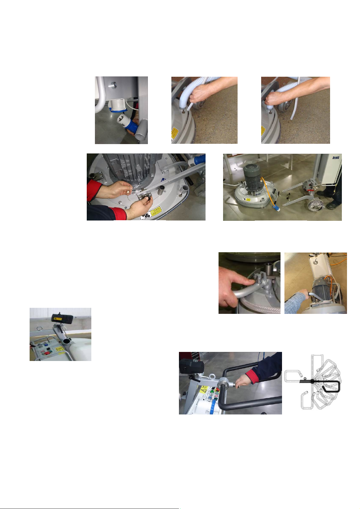
WaterFlowControlUnit..............................................................9
AdjustingAndMountingTools.....................................................9
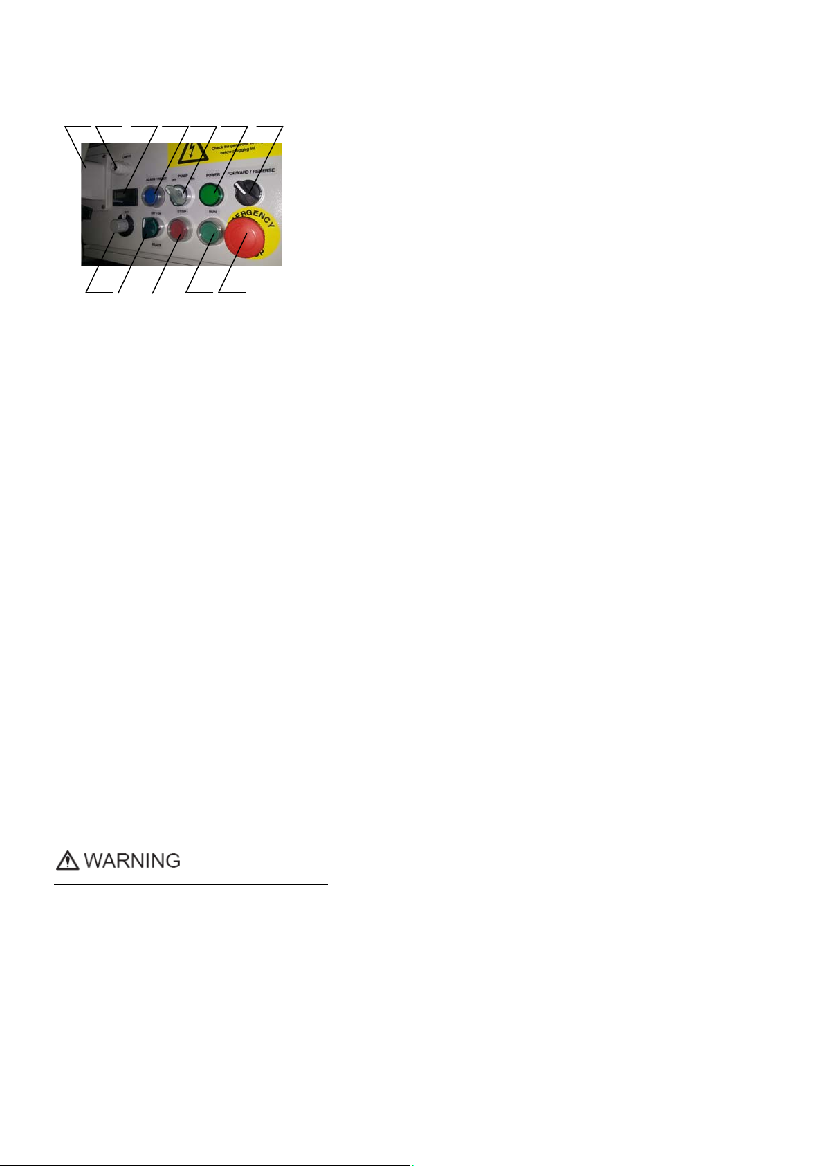
TheControlBoard......................................................................10
StartingTheMachine.................................................................10
OperatingTheMachine.............................................................10
StoppingTheMachine...............................................................10
Alarm.........................................................................................10
5.ToolsAndAccessories...........................................................11
Weights......................................................................................11
ToolHolderKey..........................................................................11
FoamPlate.................................................................................11
SecurityPlateForQuickchangePads.........................................11
6.PopularTools.........................................................................12
RecommendedTools.................................................................12
7.MaintenanceAndInspection................................................13
Cleaning.....................................................................................13
CheckDaily................................................................................13
CheckEvery200WorkingHours................................................
13
CheckEvery400WorkingHours................................................13
Vacuum......................................................................................13
WaterLeaks...............................................................................13
MechanicalParts........................................................................13
ElectricalSystem........................................................................13
Lavina®30L‐XElectricalSchemesYaskawaConnectionMain
CircuitTerminals........................................................................14
Lavina®30L‐X‐HVElectricalSchemesWithYaskawaInverter..15
Lavina®30L‐X‐HVElectricalSchemesYaskawaConnectionMain
CircuitTerminals........................................................................15
8.Troubleshooting....................................................................16
IndexOfProblemsAndSolutions..............................................16
8.1ReplacingPowerCordAndPlugs.........................................16
8.2DismountingAndMountingToolHolderToChangingV‐Rings
AndFelt‐Rings............................................................................16
8.3DisassemblingAndMountingToolHolderToChangeBuffers
AndElasticElement...................................................................16
8.4CorrectingSagOfTheUsedPlanetaryChain.......................18
8.5MountingNewPlanetaryChain..........................................18
8.6ReplacingThePlanetaryDrivingChainWheelAndPlanetary
Tensioner...................................................................................19
8.7TensioningAndReplacingTheBelts....................................20
8.8ReplacingThePlanetaryDrivenChainWheel......................22
8.9ReplacingThePulleyUnits...................................................22
8.10ReplacingThePlanetaryUnit.............................................23
8.11MotorConnection..............................................................23
8.12FaultDiagnosisInverterYaskawaV1000...........................24
9.Disposal.................................................................................26
10.Manufacturer’sContacts.....................................................26
11.SpareParts..........................................................................27
AssemblyAndPartsSpecifications.............................................27
1.Lavina®30L‐XGeneralParts..................................................27
2.Lavina®30L‐XTopCover1Parts..........................................27
3.Lavina®30L‐XTopCoverParts2............................................28
4.Lavina®30L‐XBottomCover1Parts.....................................28
5.Lavina®30L‐XPlanetaryDriveParts......................................29
5.1.Lavina®30L‐XPulleyUnitAssembly.................................30
6.Lavina®30L‐XBottomCover2Parts.....................................30
7.Lavina®30L‐XWaterTankParts.............................................31
8.Lavina®30L‐XToolHolderParts............................................31
9.Lavina®30L‐XCarriageParts..................................................32
10.Lavina®30L‐XControlBoxParts200‐240Volt....................33
Lavina®30L‐XControlBoxparts200‐240Volt............................33
11.Lavina®30L‐X‐HVControlBoxParts440‐480Volt...............34
Lavina®30L‐X‐HVControlBoxParts440‐480Volt....................34

Superabrasive UserManual OriginalLanguageLavina®30L‐X/Lavina®30L‐X‐HV 1/2015
5
1.GENERALINFORMATION
Thisowner’smanualisintendedfortheoperatoroftheLavina®Xmachine,theservicingtechnicianaswellasforanyone
involvedwithoperatingorservicingthemachine.Werecommendthatyoureadtheinstructionsverycarefullyandfollowthem
strictly.Themanualincludesinformationaboutassembling,using,handling,adjustingandmaintainingyourLavina®Xfloor
grindingandpolishingmachine.
MANUFACTURER
Superabrasivewasfoundedin1987,asamanufacturerofhighqualitydiamondtoolsforthestoneandconcreteindustry.Today,
Superabrasiveisoneoftheworld’sleadingcompaniesintheproductionofdiamondtoolsandfloorgrindingmachinery.At
Superabrasive,westrivetodelivertheverybestsolutionstoourcustomers,andenablethemtoworkmoreefficiently.
GENERALDESCRIPTION
TheLavina®Xmachineisintendedforgrinding,polishingandbuffingconcrete,marble,
granite,limestone,andterrazzosurfaces
withdiamondtools.
TheLavina®Xmachineisathree‐discmachine,whichcanbeuseddryaswellaswet.
Forbestresults,useonlytoolsmanufacturedorrecommendedbySuperabrasiveandits
distributors.Additionally,themachinecouldbeusedforgrindingwoodfloorsurfaces.
TheLavina®Xmachineismanufacturedandfittedfortheabove‐
mentionedapplicationsonly!Everyotherusemaypossessriskstothepersonsinvolved.
MACHINECHARACTERISTICS
TheLavina®Xmachineismadeoftwomaincomponentsections:
MAINDESIGN
Thetwomaincomponentsections,arethecarriageandmainhead.
Thehandle(Fig.1.2)ontheframeisadjustableinheightandallowstheoperatortoworkin
acorrectandsafeworkingposture.
Thehalogenspotlight(Fig.1.2)enablestheoperatortoworkindarker
areas.
Existinglightingsystemdoesnotreplaceadequateoverhead
lighting.
Thecontrolsarepositionedontopoftheelectricalbox(fig.1.3)
Theelectricalbox(fig.1.3)containstheelectricswitchingdevicesandtheinverter.
Themainfeedingcableisconnectedwithaplugandsocketontop.Themotorfeeding
cableispluggedintothesocketlocatedonthebottomofthebox.
Thetankisontheoppositesideoftheframe,sothattheweightofthe
waterhasnoinfluenceontheoperationofthemachine.Theframeweight,ontheother
hand,isfullyabsorbedbythedrivingwheels.Anelectricpumpspraysthewaterthrougha
frontsprayerorinternal.
Themotorismountedonthebaseplateandisdrivingthethreeheadswithabeltsystem.
Theplanetaryheadisdrivenbyasimplexrollerchain.
ENVIRONMENTALCONDITIONS
ThetemperaturerangeforoperatingtheLavina®Xmachineoutdoorsisbetween41°Fand86°For5°Cand30°C.Neverusethe
Lavina®Xmachineduringrainorsnowwhenworkingoutdoors.Whenworkingindoors,alwaysoperatethemachineinwell‐
ventilatedareas.
ELECTRICALCONNECTION
Thevoltage(Volt)andpower(Ampere)aredisplayedonalabelontheelectricalcontrolboxtoavoidanyincorrectconnection.
Refertothesebeforeconnectingthepower.Toavoidelectricalshocks,makesurethegroundpowersupplyisfunctioning
properly.
Figure 1.2
Fi
g
ure 1.3
Figure 1.1

Superabrasive UserManual OriginalLanguageLavina®30L‐X/Lavina®30L‐X‐HV 1/2015
6
VACUUMCONNECTION
Aconnectionforavacuumdustextractorislocatedonthecarriage.TheLavina®Xmachinedoesnotincludeavacuumdust
extractor.Thecustomermustpurchasethevacuumdustextractorseparately.ThehoseofthevacuumextractormustbeØ50
mmandcanbeglidedoverthepipe.Thevacuumdustextractormustbeadaptedforfloorgrindersandhaveaminimumair
displacementof320m3/hwithanegativevacuumof21kPa.
TECHNICALDATA
VIBRATIONS
ThevibrationsofthemachinearewithinthelimitsofdirectivesandharmonizedstandardsfromtheEuropeanUnionwhenthe
Lavina®Xisoperatedwiththerecommendedtoolsandinnormalconditions.
SONOROUSEMISSIONS
ThesonorousemissionsarewithinthelimitsofdirectivesandharmonizedstandardsfromtheEuropeanUnionwhenthe
Lavina®Xisoperatedwiththerecommendedtoolsandinnormalconditions.However,aspreviouslystated,theoperatormust
wearearprotectors.
LABELDATA
ThedataonthelabelprovidesthecorrectVoltageandkW(neededforoperationalpurposes);
Weight(neededfortransportationpurposes);productionyearandserialnumber(neededformaintenancepurposes).
CUSTOMERSERVICE
ForcustomerassistanceandtechnicalsupportcallyourlocaldistributororcallSuperabrasiveInc.at1‐800‐987‐8403orvisitusat:
www.superabrasive.com
,whereyoucandownloadacopyofthismanual.
2.SAFETYINSTRUCTIONS
RECOMMENDEDUSE
TheLavina®Xmachineisdesignedandmanufacturedtogrindand
polishconcrete,terrazzo,andnaturalstonefloors.Itcanbeused
forrenovationaswellasforpolishing.Themachineisdesignedfor
dryorwetuse.Whenusingitdry,useavacuumofappropriatesize.
Formoreinformation,pleaserefertothechapteronhandlingthe
vacuumconnection.
PROHIBITEDUSE
ThemachineMUSTNOTbeused:
Forapplicationsdifferentfromtheonesstatedinthegeneral
descriptionchapter.
Fornon‐suitablematerials.Inenvironmentswhich:
-Possessrisksofexplosion,
-Possesshighconcentrationofpowdersoroilsubstancesin
theair,
-PossessrisksoffireFeatureinclementconditions,
-Possesselectromagneticradiation.
PREPARATIONFORWORK
Makesurethat:
Youhaveclosedtheworkarea,sothatnopersonunfamiliar
withoperatingthemachinecanenterthearea.
Thetoolplateandtoolsareadjustedtothemachine
properly.
Therearenomissingpartsofthemachine
Themachineisinuprightworkingposition.
Theprotectiondevicesareworkingproperly.
Theelectricalcableisfreetomoveandfollowthemachine
Lavina®30L‐XLavina®30L‐X‐HV
Voltage/Hz3phx200‐240V50‐60Hz 3phx440‐480V50‐60Hz
AmperageMax45Amps Max30Amps
Power11kW15HP 11kW 15HP
Toolholderrpm300‐1100rpm 300‐1100rpm
Workingwidth765mm30.1” 765mm 30.1”
Tooldiameter(QCPlate)3x335mm3x13.2” 3x335mm 3x13.2”
Weight308kg680lbs 308 kg 680lbs
Grindingpressure193kg425 lbs 193 kg 425lbs
Additionalweightmax2x29kgmax2x64lbs max2x29kg max2x64lbs
Applicationwetanddry wetanddry
VacuumhoseportYesYes
Watertankcapacity20l5.2gal 20l5.2gal
Waterfeedwithpump(peripheralandfront) withpump(peripheralandfront)
Cablelength17.4m57ft 17.4m57ft
MachineLxWxH1930x805x1180mm76x32x46.5” 1930x805x1180mm 76x32x46.5”
PackingCrateLxWxH 1570x730x1100mm61.8x28.7x43.3” 1570x730x1100mm 61.8x28.7x43.3”

Superabrasive UserManual OriginalLanguageLavina®30L‐X/Lavina®30L‐X‐HV 1/2015
7
easily.
Inordertokeeptheelectricalcablefrombeingdamaged,no
vehicleshouldcrossthezonewhereelectricalcablesare
situated.
PROTECTIONDEVICES
Themachineisequippedwithseveralprotectiondevices
includingthefollowing:
Anemergencystopbutton
Aprotectionskirtandahoodforprotectingthetoolplates.
Thesedevicesprotecttheoperatorand/orotherspersonsfrom
potentialinjuries.Donotremovethem.Beforeusingthemachine,
pleaseensurethatallprotectiondevicesaremountedand
functionproperly.TheSecurityplatepreventstheQuickChange
padstofromlooseningduringwork
ARRESTFUNCTIONS
Functionsofarrestingofthemachinearefollowing:
Buttontostopthemotor(category1)
Emergencybutton(category1)
SAFEUSE
TheLavina®Xisdesignedtoeliminateallriskscorrelatedwithits
use.However,itisnotpossibletoeliminatetherisksofaneventual
accidentwiththemachine.Unskilledoruninstructedoperatormay
causecorrelatedresidualrisks.Suchrisksare:
PositionRisks:duetooperator’sincorrectworkingposition
TanglingupRisks:duetowearinginappropriateworking
clothes
TrainingRisks:duetolackofoperationaltraining.
NOTE::Inordertoreduceallconsequencesoftheabove‐
mentionedrisks,weadvisethatmachineoperatorswillfollow
theinstructionsinthemanualatalltimes.
RESIDUALRISKS
Duringthenormaloperatingandmaintenancecycles,theoperator
isexposedtofewresidualrisks,whichcannotbeeliminateddueto
thenatureoftheoperations.
BEFOREYOUBEGIN
Workingareamustbeclearfromanydebrisorobjects.
Afirst‐timeoperatormustalwaysreadthemanualandpay
attentiontoallsafetyinstructions.
Allelectricconnectionsandcablesmustbeinspectedfor
potentialdamages.
Groundwiresystemofthepowersupplymustbealso
inspected.
Performgeneraldailyinspectionsofthemachineandinspect
themachinebeforeeachuse.
Alwaysinspectthesafetydevices:MounttheSecurityplatefor
theQuickChangepads.
Theemergencybreakmustbeclearandworking
Thetoolprotectormustbeworking
Themachinemustbeclean
Neveroperatethemachineintherain!
Confirmthattherearenomissingpartsespeciallyafter
transportation,repairormaintenance.
Beforefillingthewatertankwithwatermakesure
themachineisnotworkingandthemainswitchis
turnedoff.
Beforeturningonthemachinemakesurethatthebaseis
placedonthefloor,themachineMUSTNOTbeinanupright
positionwhenturnedon!
OPERATINGMACHINE
WhenoperatingtheLavina®X,makecertainthatthereisno
one,butyouaroundthemachine.
Neverleavethemachineunattendedwhileworking.
Theelectricalcablemustmovefreelyandmustbedamage‐
free.
Thewaterhosemustmove
freelyandmustbedamage‐free.Checktomakesurethe
floor,youarepreparingtoworkon,iseven.Iftheflooris
uneven,itmaydamagethemachine.
AFTERWORKISCOMPLETED
Cleanthemachineanditssurroundingsproperly
Emptyandcleanthewatertank
Unplugthemachineandwinduptheelectricalcable
Storethemachineinasafeplace
THEWORKAREA
Makecertainthatpeopleorvehiclesdonotenterthework
area.
Avoidcablesandhosesbeingintheway.
Alwayscheckthefloorfordebris
PERSONALPROTECTIVE
EQUIPMENT(PPE)
Alwayswearsafetyshoeswhenworkingwiththemachine.
Alwayswearearprotectorswhenworkingwiththe
machine.
Allpersonnelintheimmediateworkareamustwearsafety
glasseswithsideshields.
Alwayswearsafetygloveswhenchangingthetools.
Alwayswearclothessuitablefortheworkenvironment.
OPERATOR
TheLavina®Xmachine.
Theoperatormustknowthemachine’sworkenvironment.
Onlyoneoperatoratatimecanworkwiththemachine.
Theoperatormustbeproperlytrainedandwellinstructed
prioroperatingthemachine.
Theoperatormustunderstandalltheinstructionsinthis
manual.
Theoperatormustunderstandandinterpretallthedrawings
anddesignsinmanual.
Theoperatormustknowallsanitationandsafetyregulations
pertainingtotheoperationof
Theoperatormusthavefloorgrindingexperience.
Theoperatormustknowwhattodoincaseofemergency.
Theoperatormusthaveanadequatetechnicalknowledge
andpreparation.

Superabrasive UserManual OriginalLanguageLavina®30L‐X/Lavina®30L‐X‐HV 1/2015
8
3.HANDLINGANDTRANSPORTATION
SPLITTING THE CARRIAGE FROM THE MAINHEAD
Unplugthemotor
cableplugfromthe
controlboxand
disconnectthewater
hosefromthemain
headbypullingitout
(Fig.3.1)(Fig.3.2).
Windtheelectrical
cableonthecarriage.
Releasethepinsets
whichattachthe
headtothe
carriage(Fig.3.4).Pull
outthevacuum
hoses(Fig.3.3),and
dismountthehead
fromthe
carriage(Fig.3.5).
Theheadofthe
LAVINA®Xmachine
hasonebarfor
supportandisusedas
handlesforeasymovingandtransportation.
LIFTTHEMACHINEFROMWORKINGTOTOOLMOUNTINGPOSITION
Pushthelockthehandledownandswivelittothefront(Fig.3.6.1).Pullthe
handleupandensuretheheadisastableuprightposition,for
mounting/dismountingthetool.Ensurethatthewatertankisemptybefore
flippingthemachine.Pulltheheadinuprightposition(Fig.3.6.2).
LIFTING
Liftingthemachinebycraneispossiblewiththeeyebolt,whichismounted
onthecarriage(seeFig.3.7).Theeyeboltand
machineconstructionisratedonlyforthe
weightofthemachine.Donotlistanyother
leadsonthemachine.Alwaysusehoistingequipmentratedfor300kgor660lbs.
ADJUSTINGTHEHANDLE
TheHandleontheframeisadjustableinheightandallows
theoperatortoworkinacorrectandsafeposture.The
unlockingisbypullingthehandle(fig.3.8.1)Thelockingis
automaticallyunderactionofthespring(Fig.3.8.2)shows
allpossiblepositionofthehandle.Choosetheupright
positiontomoveeasythemachine.
Figure 3.8.2Figure 3.8.1
Figure 3.6.1 Figure 3.6.2
Fi
g
ure 3.7
Figure 3.4 Figure 3.5
Figure 3.1 Figure 3.2 Figure 3.3

Superabrasive UserManual OriginalLanguageLavina®30L‐X/Lavina®30L‐X‐HV 1/2015
9
STORAGE
AlwaysstoreandtransporttheLavina®X
machineinadryplace.Nevertransport
theLavina®Xmachineunprotected;itmay
bedamagediftransportedunprotected
duringrainorsnow.
Whenstoringthemachinethetemperaturemayfalldowntoortolessthan32F(or0oC)youshouldemptythewaterfromthe
systemusingthefollowingsteps:
‐Pulloutthehoseofthetank(Fig.3.9)
‐Usingcompressedairblowoutthewaterfromthesystemforthetwopositionsoftheturn‐cock(Fig.3.10,Fig.3.11).
4.OPERATION
PRELIMINARYCONTROLS
Inspecttheworkingareaasexplainedinthesafetyinstructions.Forwetuse,fillthewatertankwhentheelectricalcableis
disconnected.Connectthevacuumextractorandensurethatthevacuumhoseisclearandthatitwilleasilyfollowthemachine.Plug
inthemachineandmakesurethatthepowercordisfreetofollowthedirectionoftheworkingLavina®Xmachine.
WATERFLOWCONTROLUNIT
Theoperatorcanchoosethewatersprayerinthefront
whenthetapisinthehorizontalposition(Fig.4.1),the
waterwillsprayunderthecoverofthemachinewhen
thelevelisintheverticalposition(Fig.4.2).Theflow
regulatingvalvelocatedonthetank(Fig.4.3)is
increasingorreducingthewaterflowtothe
working
area–infrontofthemachineorunderthemainhead
coverofthe
machine.
ADJUSTINGANDMOUNTINGTOOLS
TheHolderA43inLAVINA®Xcanworkwitheither3or6
bufferswhichwillchangeitselasticity.Youcanmakethe
changeafterdismountingtheholderaspertheinstructionin
TROUBLESHOOTING.InLavina30L‐Xtheholderisinitially
mountedwith6buffers.
Mountthetoolsonlyafterensuringthatthereisenough
diamondbondmaterialleft.Besurethattheplatesarealways
cleanbeforemounting.WARNING:Alwayssecurethe
“QuickChange”padswiththesecurityplate(Fig.4.4),lockwiththetoolholderkey(Fig.5.3).DiamondtoolswithVelcroareattachedto
three9inchfoamplates(Fig.4.5).Thefoamplatesaremountedonthekeylock(butterfly).Alwaysusethetoolholderkey(Fig.5.3).
Figure 3.9 Figure 3.10 Figure 3.11
Figure 4.2 Figure 4.3
Figure 4.1
Figure 4.5
Fi
g
ure 4.4

Superabrasive UserManual OriginalLanguageLavina®30L‐X/Lavina®30L‐X‐HV 1/2015
10
THECONTROLBOARD
1. Powercableplug
2. Lampcablegland
3. DigitalRPMindicatorIndicatestherevolutionperminuteofthegrindingplates(not
therevolutionperminuteoftheentire
4. ALARM/Resetbuttonresetsthealarmoftheinverter.Buttonlightsbluewhenthe
invertergoesintoalarmmode
5. WaterpumpswitchLightsorangewhenthewaterpumpisworking.
6. Powerledlightsgreenwhenthepowerison
7. Forward/Reverseswitchchooseforwardforclockwiserotationofthegrindingplates
orreverseforanti‐clockwiserotationofthegrindingplates(Recommended)
PreferredoperatingdirectioniswhentheswitchisonpositionF.Theproperdirection
ofrotationofthemotor(anti‐clockwise)isindicatedbyarrowonitscover.
8. PotentiometerchangestheRPMofthegrindingplatesfrom300‐1100rpm
9. READYOFF/ONswitch.TurningONtheswitch,itlightsshowingthatthemachineisinstandbymode.
TurningOFFtheswitch,itlightsoffshowingthemachineisoutofstandbymode.Afterreleasingtheswitchitgoesbackin
centralposition.
10. STOPbuttonstopsthemotor
11. RUNbuttonstartsthemotor
12. EmergencybuttonusedinEmergencysituationsforstoppingthemotor.
STARTINGTHEMACHINE
First,followthedirectionsinchapterSafetyDevicesandSafetyInstructions.Next,pulltheemergencystop(12)turntheReady
switch(Fig.4.69)inpositionONtoputthemachineinstandbymode.Checkthepotentiometer(8)andensurethatitissetatthe
workingspeed.Ifworkingwet,addwatertothefloorsurface.Ifworkingdry,omitthisstep,andinstead,switchonthevacuumunit.
Finally,holdthemachinefirmlyandpushtheRUNbutton(11).
OPERATINGTHEMACHINE
Guidethemachineinstraightlinesacrossthefloor,andwitheachnewlineoverlapalittlebitofthepreviouslycompletedsurface.
Workataconstantspeed,allowingthetoolstimetoworkataspeedappropriateforthetools’gritsize.Avoidvibrations.Donotstop
theLavina®Xononespotwhilethetoolsarestillworkingbecausetheywillleavemarksonthefloors’surface.Whenworkingwet,
firstchoosethewatertap(Fig.4.2)andthepositionforthewaterfeed,periodicallystarttopumpandreleasewaterontothefloor’s
surface(Fig.4.6Pos.6).Whenworkingdry,checkthefloor’ssurfaceperiodicallytoensurethatdustisnotaccumulatingonthe
surface,alsocheckregularlytomakesureyourvacuumisworkingproperly.
STOPPINGTHEMACHINE
Thestoppingofthemachinemustbedonegraduallyuntilthemotorstops.Donotstopmovingthemachinebeforearrestingthe
Motor,asthetoolscoulddamagethesurface.
Tostopthemachine:
1.PushtheSTOPbutton(10).
2.TurntheOFF/ON(9)switchinpositionOFF,thiswillcutthevoltagetotheinvertorandthegreenlightwillturnoff.
WhileworkingdonotturnoffdirectlyfromtheswitchREADYOFF/ONorfromtheEmergencyStop,butfollowtheabove
mentionedsteps1and2.
UsetheEmergencybutton(12)onlyinemergency.
Remembernottoholdthemachineinonespotbeforeturningoffthemotormotor.
ALARM
TheResetbutton(4)willlightwhentheinvertergoesinalarmmode.Themostcommonfailureismotorinoverload.Toresetthe
modepushresetbutton(4).Acodeontheinverter’sdisplayindicatesthetypeofthealarm.Whenthesamealarmisrepeated
severaltimesitisobligatorytofindandeliminatethereasonforit,otherwisetheinvertercanbedamaged.
89101112
1245673
Figure 4.6

Superabrasive UserManual OriginalLanguageLavina®30L‐X/Lavina®30L‐X‐HV 1/2015
11
5.TOOLSANDACCESSORIES
WEIGHTS
Superabrasiveoffersadditionalweightsforincreasingtheproductivityofthemachine(Fig.5.1).
Eachadditionalweightweighsabout64lbsor29kg.Eachindividualapplication,typeand
conditionofsurface,powercapacityoftheoutlet,etc.willdeterminethenumberofweights
youcanusewithouttrippingabreaker.Theweightstacksontothreepoststhatarearoundthe
outerbowl(Fig.5.2).Theadditionalweightsdependonthetools;itisnotalwayspossibletoass
weights.Sometoolsworktooaggressivelyandthemachinecanstop.Theweightcanbe
orderedwithitemnumberA08.00.00.00
TOOLHOLDERKEY
Thetoolholderkey(Fig.5.3)isusedforadjusting,mountinganddismountingofthefoam
plates.Alwaysusethekeyformounting.
ItemnumberisA03.00.00.00
FOAMPLATE
DiamondtoolswithVelcroaremountedonthefoamplate13.2“(Fig.5.4).Thefoam
plateismountedonthe“QuickChange”System.
ItemnumberisLV‐13,5‐FP‐S
SECURITYPLATEFORQUICKCHANGEPADS
Plate(Fig.5.5)usedtoensurethe
“QuickChange”pads.ItemnumberisA38.00.02
Figure 5.3
Figure 5.1
Figure 5.2
Figure 5.4
Figure 5.5

Superabrasive UserManual OriginalLanguageLavina®30L‐X/Lavina®30L‐X‐HV 1/2015
12
6.POPULARTOOLS
RECOMMENDEDTOOLS
QuickChangeSystemandToolingfeatureextremelyfastandconvenienttoolchanges,andalongtool
life,providingforgreatlong‐termcostsavings.TheQuickChangepadsareproducedinfourdifferent
bondsforsuperhard,hard,mediumandsoftconcrete,inavarietyofgritsizes.Theyareofferedwith
1or2buttonsorrectangularsegments,whichallowsyoutocustomizetheaggressivenessofthecut.
Calibragrindingdiscs:ourpopularceramicbonddiscsaredesignedfortheremovalofdifficultscratches
andtheysaveyouvaluabletimebyeliminatingtheneedformultiplepasseswithmetaltools.Theycanbe
used
wetordry,andarebestforhardconcreteapplications.
Theyare3‐inch,withincludedVelcrobackattachment.
NATO®polishingdiscsfeatureaspecialresinformuladesignedforbothwetanddryapplicationsandauniquedesignwith
widechannelsallowingforworkonacleanersurfaceandensuringaqualitypolish.Availablein3and4insizes.Theyarewith
includedVelcroattachment.
V‐HARR®PremiumPolishingPadsaredesignedformechanicallypolishingandrestoringconcrete;alsoidealforterrazzoand
hardstonefloors.V‐HARR®padsareofferedinawidevarietyofdiametersandgritsizestoaccommodatemanyapplications.
Dryuseisstronglyrecommended.
ShinePro®arehighqualitydiamond‐impregnatedpadsforfloormaintenance.Availableinavarietyofsizes,andaregreatfor
dailyuse.Whenusedwet,theyrequireonlywater(nowaxorchemicalsneeded)andareaveryenvironmentallyfriendlysolution
formaintainingfloors.
UseOnlySuperabrasive’sRecommendedTools.ForMoreToolingOptions,Visitwww.superabrasive.com

Superabrasive UserManual OriginalLanguageLavina®30L‐X/Lavina®30L‐X‐HV 1/2015
13
7. MAINTENANCE AND INSPECTION
CLEANING
Keepyourmachineclean.Cleaningthemachineinaregularbasiswillhelpdetectandsolvepotentialproblemsbeforetheycan
causedamagetothemachine.Mostimportantly,checkandcleanthetoolplateconnections,powercords,plugs,vacuumhoses,
andwatertank.
CHECKDAILY
AfteroperatingtheLavina®Xmachine,theoperatorshouldconductavisualinspectionofthemachine.
Anydefectshouldbesolvedimmediately.Payattentiontopowercords,plugs,vacuumhoses,loose
boltsorscrews.
Toolholders:Buffersandelasticelementareconsumablesandmustbevisuallycheckedonadailybasis
andreplacedifnecessary.Makesuretheflangesordiscsaresecurelylockedinplace.Thekeylock
holders(butterflies)shouldalsobechecked.
Checktherubberbuffersandmakesuretheholdersaresecure.Theflangeholdingthebuffers(Fig.7.1‐1)
hastobefirmlysecuredtotheunit.Ifthereisagapseenhere,thatmeansthescrewssecuringthe
holderareloose.Thescrewshavetobetightenedimmediatelytosafelyoperatethemachine.Working
withloosescrewscouldcauseseriousdamagetothemachine.Thetighteningforceofthescrewshasto
be22‐25N.m(16‐18ft/lbs).
Itisveryimportanttoregularlycheckthescrewsthatsecurethe“QuickChange”holdertothesafetypart
(Fig.7.1‐2),sothattheholderwillnotflyawayifthebuffersgetdamaged.The“QuickChange”shouldbe
cleanalso.
CHECKEVERY200WORKINGHOURS
Every200workinghours,theoperatorshouldinspectallpartsofthemachinecarefully.
Mostimportantly,inspectandcleanthetoolplateconnections,powercordplugs,
vacuumhosesandwatertankandfilter.Also,checkthewaterflowofthepump.Check
theguardassembly.Makecertainthewheelsarecleanandrotateproperly.Inspectthe
controlbuttons.Iftherearedefectivecontrolparts,theyshouldbereplaced
immediately.Replacewornvacuumandwaterhoses.
Opentheservicecoveronthemotorbase(Fig7.2)(Fig7.3)tocheckofthe
planetarychain.Lubricatethechainwithspeciallubricantforchainsandcorrectthesagif
needed.Forsaggingcorrection(SeeTROUBLESHOOTING8.4).
Dismountthetoolholders(SeeTROUBLESHOOTING)andreplaceallparts
(elasticelement,buffers,sealercaps,“O”rings)thathavetheslightestdamage.
CHECKEVERY400WORKINGHOURS
Besidesthechecksof200workinghours,replacesealerandV‐ringslikedescribedinchapter“TROUBLESHOOTINGDISMOUNTING
TOOLHOLDERSTOCHANGINGV‐RINGSANDFELT‐RINGS.
VACUUM
Asstatedpreviously,frequentlycheckhosesandotherpartsforclogging.
WATERLEAKS
Leakingpartsshouldbereplacedimmediatelybecausethewatercoulddamageyourmachine.
MECHANICALPARTS
Partssuchasthebelts,sealrings,caprings,spiders,buffersandguardassemblyaresubjecttowearandmustbereplacedasneeded.
ELECTRICALSYSTEM
Dustshouldnotenterthecontrolbox,asitwilldestroythecontrols.Remove(blowout)anydustpresent
Figure 7.1
Figure 7.3
Figure 7.2

Superabrasive UserManual OriginalLanguageLavina®30L‐X/Lavina®30L‐X‐HV 1/2015
14
Lavina®30L‐XElectricalschemeswithYaskawaInverter
200‐240Volt
LAVINA®30L‐XELECTRICALSCHEMESYASKAWACONNECTIONMAIN
CIRCUITTERMINALS
Themotorisconnectedin“Delta”
(triangle)230Volt,
reminderforthewireconnectionof
themotor.

Superabrasive UserManual OriginalLanguageLavina®30L‐X/Lavina®30L‐X‐HV 1/2015
15
LAVINA®30L‐X‐HVELECTRICALSCHEMESWITHYASKAWAINVERTER
440‐480Volt
LAVINA®30L‐X‐HVELECTRICALSCHEMESYASKAWACONNECTION
MAINCIRCUITTERMINALS
Figure 7.4 /scheme 1/
Themotorisconnectedin“Star”380
Volt,
reminderforthewireconnectionof
themotor.

Superabrasive UserManual OriginalLanguageLavina®30L‐X/Lavina®30L‐X‐HV 1/2015
16
8.TROUBLESHOOTING
INDEXOFPROBLEMSANDSOLUTIONS
8.1REPLACINGPOWERCORDANDPLUGS
Whenreplacingthepowercordorplugsalwaysusecordsandplugswiththesamespecificationsastheoriginalones.
Neveruselowerqualityordifferenttypesofcordsandplugs.
Inaddition,takeintoconsiderationthedistancebetweentheapplianceandtheelectricalsource.Thegreaterthedistance,thegreater
theresistanceandthelesscurrentthatwillbeavailableattheotherend,therewillbeavoltagedropandtheinverterwillsigninto
alarmmode.Thiswillalsohappenifseveralmachinesareworkingonthesamelineorwhenthegeneratorisunderrated.Ingeneral,
ourstandardpowercablecanbedoubledinlength;ifyouneedlongerlengthsthenyoumustreplaceallthecableswithcablesofa
biggergaugerateforthelengthandamperage.
8.2DISMOUNTINGANDMOUNTINGTOOLHOLDERTOCHANGINGV‐RINGSANDFELT‐RINGS
Tocheckorreplacethebuffersandtheelasticelements,thetoolholdershavetobedismounted.
Youwillneeddeepmetricsocket13mmwithoutsidediameternotmorethan3/4intounscrewthefourbolts(Fig.8.2.1)andremove
theholder(Fig.8.2.2)Whenthetoolholderisdismounted,youcanchangethesealers(V‐RingandFelt‐Ring).
BylooseningfourHexcapflangebolts(Fig.8.2.3)theadaptorcomesloose.Unscrewthesixscrewsofthecap(Fig.8.2.4)holdingthe
felt‐ring.TakeouttheFelt‐Ring,adaptorandV‐Ring.
MounttheV‐RingwiththesmallestlipoftheVtoinside(Fig.8.2.5)justpushtheV‐Ringsothetopisonthesamelevelasthepulley
top(Fig.8.2.6).ThentaketheadaptorandpushtheV‐Ringdownwiththeadaptor(Fig.8.2.7).ThelowestlipoftheV‐Ringshouldonly
barelytouchitsglidingsurface;alsoneverpushtheV‐Ringdownwithfingers.MounttheadaptorandtheFelt‐Ringontop(Fig.8.2.7).
Closethesealerswiththecap(Fig.8.2.8)andscrewthebolts.Alwaysusetheoriginalbolts.
8.3DISASSEMBLINGANDMOUNTINGTOOLHOLDERTOCHANGEBUFFERSANDELASTICELEMENT
WhentheTOOLHOLDERisdisassembledyoucanchangedefectiveparts–elasticelement,buffers,etc.
Liftthelockingpin(Fig.8.3.1)todismounttheretainingwasher(Fig.8.3.2).Takeoutthescrewsonthebuffersandthenutsofthe
elasticelement(Fig.8.3.3;Fig.8.3.4).RemovetheelasticelementfromtheQCplate(Fig.8.3.5).Whiletheholderisdismounted
(Fig.8.3.6;Fig.8.3.7)cleanthepartsandreplacethedefectivewithnewones.Assembletheholderwithnewbufferswithnewscrews
andnewelasticelement.Puttheretainingwasher(Fig.8.3.8)andpushthelockingpin(Fig.8.3.9).Thiswillpreventthefallofthe
washerwhenmountingtheholderonthemachine.
Figure 8.2.1 Figure 8.2.2 Figure 8.2.3 Figure 8.2.4
Figure 8.2.5 Figure 8.2.6 Figure 8.2.7 Figure 8.2.8

Superabrasive UserManual OriginalLanguageLavina®30L‐X/Lavina®30L‐X‐HV 1/2015
17
Figure 8.3.13
Makesurethefourboltsholdingtheadaptor
(Fig.8.3.12)arereliablytighten.Mounttheholderon
themachineusingthesamesocketasmentionedin
8.2(Fig.8.3.10;Fig.8.3.11).Theretainingwasherfits
intothecentralholeCofadaptorandthefourbolts
intothethreadholesТ(Fig.8.3.12).Theholderis
centeredontheoutsidediameteroftheadaptor.
Ensuretheconnectionoftheholderontheforehead
oftheadaptorandthentightevenlythefourbolts.
Tighteningforceoftheboltshastobe
22...25N.m(16...18ft/lbs).Mountingtheholder
withoutretainingwasher(Fig.8.3.2)isINADMISSIBLEbecausethesecuritysystempreventingtheseparationofpartoftheholder
incaseofbrokenbuffersandelasticelementwillnotfunction!
Youcanchangethebutterflyoftheholderwithout
dismountingtheholderofthemachine.
Fig.8.3.13is3‐Dsectionviewoftheholder,
showingitsparts.Thenumberingisthesameasin
Spareparts.
T
C
Figure 8.3.12
Figure 8.3.10 Figure 8.3.11
Figure 8.3.5
Figure 8.3.1 Figure 8.3.2
Figure 8.3.7
Figure 8.3.4
Figure 8.3.8 Figure 8.3.9
Figure 8.3.3
Figure 8.3.6

Superabrasive UserManual OriginalLanguageLavina®30L‐X/Lavina®30L‐X‐HV 1/2015
18
8.4CORRECTINGSAGOFTHEUSEDPLANETARYCHAIN
Unscrewtheeightbolts(Fig.8.4.1)andtakeoutthecover(Fig.8.4.2)andpulloutthe
hoseofthewatersprayer(Fig.8.4.3).Liftthemachineinpositiontochangethetools.
Turnmanuallytheholdersinordertoturnthemainhead,stopwhenyouseethrough
thewindowthechaintensioner(Fig.8.4.4).
Loosenaquarterto1/2revthetwoboltsofthechaintensioner(Fig.8.4.5)thetensionershouldturnwithminimumclearence,
withoutinclination,thenunscrewtheinnernut.Totensionthechainscrewtheouternut(Fig.8.4.6).Thetensionerofthe
planetarychainshouldallowchainsagging3...5mm/1/8...3/16in/controlledinspanX(Fig.8.4.7).Whenreadyscrewthetwonuts
(Fig.8.4.6)andthescrew(Fig.8.4.5).
ATTENTION:NEVER“OVER”TENSIONTHECHAIN,THECHAINWILLBEDAMAGED
8.5MOUNTINGNEWPLANETARYCHAIN
Theplanetarychainisreplacedwithnewonewhenthestep/driveofthechaintensionerisfinishedorthereisabreakinthe
integrityofthechain.
Unscrewtheeightbolts(Fig.8.4.1)andtakeoutthecover(Fig.8.4.2)andpulloutthehoseofthewatersprayer(Fig.8.4.3).Lift
themachineinpositiontochangethetools.Turnmanuallytheholdersinordertoturnthemainhead,stopwhenyou
seethroughthewindowthechaintensioner(Fig.8.4.4).Separatethecarriagefrommainhead,pulloutmotorplug(Fig.3.1),
watertubesandvacuumtubes(Fig.3.2)(Fig.3.3).Takeoffhandle(withoutwatertubes)(Fig.8.4.3).Releasethepinsets(Fig.3.4)
whichattachtheheadtothecarriage.Takeofftheweightholders(Fig.8.5.1),machinesupport(Fig.8.5.2)andtheservicewindow
Figure 8.4.7
X
Figure 8.4.5 Figure 8.4.6
X
Figure 8.4.1
Figure 8.4.2 Figure 8.4.3 Figure 8.4.4
Figure 8.5.1 Figure 8.5.2 Figure 8.5.3

Superabrasive UserManual OriginalLanguageLavina®30L‐X/Lavina®30L‐X‐HV 1/2015
19
(Fig.8.4.2)soyoucandismountthetopcover(Fig.8.5.3).
Loosenthetwonuts(Fig.8.4.6)anduscrewthetwoscrewsofthetensioner(Fig.8.4.5)(Fig.8.5.4)(Fig.8.5.5).Takethechain
tensioner(Fig.8.5.6).Pulloutthesplitpin(Fig.8.5.7)andthechainlinkpin(Fig.8.5.8)(Fig.8.5.9).Takethechain,andputonthe
samewaythenewchain,getinthechainlinkpinandthesplitpin(Fig.8.5.9)(Fig.8.5.8)(Fig.8.5.7).
Mountthechaintensioner(Fig.8.4.6).Screwthetwoscrews(Fig.8.5.4)(Fig.8.4.5).Loosenaquarterto1/2revtheboltofthechain
tensioner(Fig.8.4.5)thetensionershouldturnwithminimumclearence,withoutinclination,thenunscrewtheinnernut.To
tensionthechainscrewtheouternut(Fig.8.4.6).Thetensioneroftheplanetarychainshouldallowchainsagging
3...5mm/1/8...3/16in/controlledinspanX(Fig.8.4.7).
Whenreadyscrewthetwonuts(Fig.8.4.6)andthescrew(Fig.8.4.5).
ATTENTION:NEVER“OVER”TENSIONTHECHAIN,THECHAINWILLBEDAMAGED
8.6REPLACINGTHEPLANETARYDRIVINGCHAINWHEELANDPLANETARYTENSIONER
Checkandrepeattheinstructionin8.5MONTINGNEW
PLANETARYCHAIN.
Unscrewboltpos.1takethechainpulleypos.3togetherwiththe
sealerpos.5.Changethesealerandmountittothechainpulley
pos.3.Applylithiumgreaseontheshaftandmountbackthe
wheelandthefrontwasherpos.2asshownon(Fig.8.6.1).Screw
theboltbyusingalwaysthe“blue”threadlockingadhesive.
Tighteningforceoftheboltshastobe9...11N.m(6.6...8ft/lbs).
Figure 9.6.1
Figure 9.5.7 Figure 9.5.8 Figure 9.5.9
Figure 9.5.6
Figure 9.5.5
Figure 9.5.4
Figure 8.6.1

Superabrasive UserManual OriginalLanguageLavina®30L‐X/Lavina®30L‐X‐HV 1/2015
20
8.7TENSIONINGANDREPLACINGTHEBELTS
Thetransmissionofthemachinehastwotimingbelts(mainbeltand
planetarybelt)ofmaintenancefreetype.Tochangethemainbeltyou
havetoremoveallholdersanddismounttheiradaptors.Dismountthe
sealing.Carefullycheckthefrictionsurface(flangesofthelowercover
andtheoutsidediameteroftheadaptors).Decideiftheyareingood
condition(wearout,smoothnessofsurface)andwhethertheycan
workuntilnextinspection.Removethebottomcover,unscrewthe
boltsontheoutskirtandthethreeboltsofthespacers(Fig.8.7.1).
Underthecoverontheoutskirtthereisasealer,andthespacershave
O‐Rings.Thechangeofallsealstogetherwiththebeltsis
recommended.
Fig.8.7.5showstheschemeofbeltslocation.Todismounttheold
beltsfirstdismounttheplanetarybeltpos.1andafterthatthemain
beltpos.6.
Todismountthemainbeltpos.6unscrewnutsonpos.4andpos.5
enoughtobeabletoturnthetensionerspos.3aroundthecentralaxle.
Cleanthewashersandspacearound,andcheckifallbearingsofpulley
unitsortensionersareingoodcondition(checkfortoomuch
clearanceorrollingnoise).Rotatingthetensionerwillallowthecentre
distancetobereducedinsuchawaythatthetimingbeltmaybefittedwithoutforce.InstallationwiththeuseofforceisNOT
permissibleatanytimeasthiscandamagethehighquality,lowstretchtensioncordandothercomponents.Thisdamageisoften
notvisible.Putthebeltsinpos.6asperthescheme,andpayattentionfortheircorrectpositionineverypulley.Screwupuntilit
stopsandloosenonthehalfmoonsthenutsonpos.4,allowingtherotationofthetensionersatminimuminclination.
Usingnutsonpos.5tightenthebelt,verifyingagainthecorrectpositionofthebelt,andthecorrectgearingineverypulley.
Rotatethegearwhiletensioningtoallowregulartensiondistributiononthebelt.Control
thetensionusingFrequencytensionTester(Optibelt3TT)(Fig.8.7.3).Tensioninspan“А”of
thebeltshouldbe120‐130Hz.Itispossiblefortensioningwhilechangingthebelttousepre‐
installedsupport(Fig.8.7.5‐2)(Fig.8.7.6)(onlywhenitsfactorypositionisnotchanged),to
limittheturnofthetensionerwhentherequiredbelttensionisdone.
ATTENTION:NEVER“OVER”TENSIONTHEBELT,THEBELTWILLBEDESTROYEDANDITWILL
NEVERRECOVERITSORIGINALTENSION
Todismounttheplanetarybelt(Fig.8.7.5‐1)unscrewthescrewofthefrontwasher(Fig.8.7.7)andthetwoscrewsoftheconical
sleeve(Fig.8.7.8).Screwonescrewinthefreethread(Fig.9.7.9),topushthewasherdown(Fig.8.7.10);taketheconicalsleeveand
thebelt(Fig.8.7.11).Youcanhelpwithaflatscrewdriverifthesleeveisnotgoingouteasy.(Fig.8.7.12).
Figure 8.7.3
Figure 8.7.1 Figure 8.7.2
Figure 9.7.4
Figure 8.7.5
Figure 8.7.6
This manual suits for next models
1
Table of contents
Other Superabrasive Sander manuals

Superabrasive
Superabrasive LAVINA 20-S-E User manual

Superabrasive
Superabrasive InovaCrete System manual

Superabrasive
Superabrasive LAVINA B21-E User manual

Superabrasive
Superabrasive Lavina 21 Series User manual

Superabrasive
Superabrasive LAVINA 30G-X User manual

Superabrasive
Superabrasive LAVINA 20N-S-OE User manual

Superabrasive
Superabrasive LAVINA 20N-S User manual

Superabrasive
Superabrasive Lavina Elite L20EU User manual

Superabrasive
Superabrasive LAVINA 38GR -X User manual