6
Tutte le operazioni vanno eseguite a spina disinserita. A fine lavoro,
od in caso di necessità, spolverare con getto di aria compressa il corpo
macchina prestando particolare attenzione alla pulizia delle feritoie di
ventilazione del motore.
Non sono ammessi altri interventi da parte dell'utente.
Per la manutenzione e la periodica pulizia delle parti interne, come spazzole,
cuscinetti, ingranaggi etc. o altre necessità rivolgersi ai Centri di Assistenza
autorizzati anche sul sito www.rupes.com sezione Service.
Utilizzare solo ricambi originali RUPES.
SMALTIMENTO
Solo per i Paesi CE: Secondo la Direttiva Europea sui rifiuti di
apparecchiature elettriche ed elettroniche e la sua attuazione in
conformità delle norme nazionali, le apparecchiature elettriche esauste
devono essere raccolte separatamente, ai fini di essere riciclate in
modo eco-compatibile. Il prodotto, quando giunge a fine vita, non deve essere
disperso nell’ambiente o gettato tra i rifiuti domestici, ma deve esse smaltito
presso i centri di raccolta differenziata autorizzati (contattare le autorità locali
competenti per conoscere dove smaltire il prodotto secondo le norme di legge).
Il corretto smaltimento del prodotto contribuisce alla tutela della salute e alla
salvaguardia dell’ambiente.
Lo smaltimento abusivo del prodotto comporta sanzioni a carico dei trasgressori.
6
SOSTITUZIONE:
CARTA ABRASIVA VELCRATA
- Asportare a strappo il foglio di carta abrasiva usato;
- applicare il nuovo foglio di carta abrasiva abrasivo (vedi “MONTAGGIO”)
CARTA ABRASIVA
- Sollevare le leve fermacarta (7) premendo sulle apposite appendici e rimuovere
foglio di carta abrasiva usato;
- applicare il nuovo foglio di carta abrasiva seguendo le istruzioni indicate nel
capitolo “MONTAGGIO DELLA CARTA ABRASIVA”
Avviare la macchina e controllare che non siano presenti vibrazioni anomale o
scentrature dell’utensile. In caso contrario spegnere la macchina
immediatamente e provvedere ad eliminare le anomalie.
AVVIAMENTO E FERMATA
- Avviamento: spingere in avanti l’'interruttore ON/OFF (2);
Per bloccare l’interruttore ON/OFF (2): premere l’interruttore verso il basso
nella parte anteriore, fino allo scatto in posizione ON.
- Fermata: rilasciare l’interruttore ON/OFF (2).
Se bloccato premere l’interruttore avvio/arresto nella parte posteriore verso il
basso e rilasciarlo in posizione OFF.
ATTENZIONE: dopo un’interruzione dell’energia elettrica se
l’interruttore ON/OFF è inserito, è necessario rilasciare
l’interruttore (vedi Fermata).
REGOLAZIONE ELETTRONICA DEL NUMERO DI GIRI
La regolazione del numero di giri si ottiene manovrando opportunamente la
rotella del regolatore di velocità (3) posta nella parte posteriore della macchina.
La scelta della velocità va fatta in funzione delle caratteristiche dei fogli di carta
abrasiva e del materiale da lavorare.
REGOLAZIONE DEL FLUSSO DI ASPIRAZIONE
Il flusso di aspirazione può essere regolato ruotando la ghiera di regolazione del
flusso di aspirazione (4).
ACCESSORI
- Fogli di carta abrasiva forati;
- Fogli di carta abrasiva forati velcrati 400x70 mm.
MANUTENZIONE
Sostituire immediatamente la piastra gomma danneggiata.
Risultati ottimali si conseguono solo con accessori originali.
Dichiariamo sotto la nostra responsabilità che l’utensile elettrico a motore
portatile, al quale fa riferimento il presente manuale, è conforme ai Requsiti
Essenziali delle Direttive:
2006/42/CE; 2006/95/CE; 2004/108/CE; 2011/65/CE.
Le prove/verifiche sono eseguite in accordo alle seguenti Normative:
EN 60745-1: 2009 + A11: 2010
EN 60745-2-4:2009+ A11:2011.
EN 55014-1: 2006 + A1: 2009 + A2: 2011
EN 55014-2: 1997 + A1: 2001 + A2: 2008
EN 61000-3-2: 2006 + A1: 2009 + A2: 2009
EN 61000-3-3: 2008
EN 50581: 2012 Vermezzo (MI),01/01/2015
IL PRESIDENTE
G. Valentini
S.p.A
DICHIARAZIONE DI CONFORMITÀ
Fascicolo tecnico presso:
RUPES S.p.A.
Via Marconi, 3A
20080 VERMEZZO (Mi) - Italy
Tutte le operazioni vanno eseguite a spina disinserita. A fine lavoro,
od in caso di necessità, spolverare con getto di aria compressa il corpo
macchina prestando particolare attenzione alla pulizia delle feritoie di
ventilazione del motore.
Non sono ammessi altri interventi da parte dell'utente.
Per la manutenzione e la periodica pulizia delle parti interne, come spazzole,
cuscinetti, ingranaggi etc. o altre necessità rivolgersi ai Centri di Assistenza
autorizzati anche sul sito www.rupes.com sezione Service.
Utilizzare solo ricambi originali RUPES.
SMALTIMENTO
Solo per i Paesi CE: Secondo la Direttiva Europea sui rifiuti di
apparecchiature elettriche ed elettroniche e la sua attuazione in
conformità delle norme nazionali, le apparecchiature elettriche esauste
devono essere raccolte separatamente, ai fini di essere riciclate in
modo eco-compatibile. Il prodotto, quando giunge a fine vita, non deve essere
disperso nell’ambiente o gettato tra i rifiuti domestici, ma deve esse smaltito
presso i centri di raccolta differenziata autorizzati (contattare le autorità locali
competenti per conoscere dove smaltire il prodotto secondo le norme di legge).
Il corretto smaltimento del prodotto contribuisce alla tutela della salute e alla
salvaguardia dell’ambiente.
Lo smaltimento abusivo del prodotto comporta sanzioni a carico dei trasgressori.
6
SOSTITUZIONE:
CARTA ABRASIVA VELCRATA
- Asportare a strappo il foglio di carta abrasiva usato;
- applicare il nuovo foglio di carta abrasiva abrasivo (vedi “MONTAGGIO”)
CARTA ABRASIVA
- Sollevare le leve fermacarta (7) premendo sulle apposite appendici e rimuovere
foglio di carta abrasiva usato;
- applicare il nuovo foglio di carta abrasiva seguendo le istruzioni indicate nel
capitolo “MONTAGGIO DELLA CARTA ABRASIVA”
Avviare la macchina e controllare che non siano presenti vibrazioni anomale o
scentrature dell’utensile. In caso contrario spegnere la macchina
immediatamente e provvedere ad eliminare le anomalie.
AVVIAMENTO E FERMATA
- Avviamento: spingere in avanti l’'interruttore ON/OFF (2);
Per bloccare l’interruttore ON/OFF (2): premere l’interruttore verso il basso
nella parte anteriore, fino allo scatto in posizione ON.
- Fermata: riportare indietro l’interruttore ON/OFF (2).
ATTENZIONE: dopo un’interruzione dell’energia elettrica se
l’interruttore ON/OFF è inserito, è necessario rilasciare
l’interruttore (vedi Fermata).
REGOLAZIONE ELETTRONICA DEL NUMERO DI GIRI
La regolazione del numero di giri si ottiene manovrando opportunamente la
rotella del regolatore di velocità (3) posta nella parte posteriore della macchina.
La scelta della velocità va fatta in funzione delle caratteristiche dei fogli di carta
abrasiva e del materiale da lavorare.
REGOLAZIONE DEL FLUSSO DI ASPIRAZIONE
Il flusso di aspirazione può essere regolato ruotando la ghiera di regolazione del
flusso di aspirazione (4).
ACCESSORI
- Fogli di carta abrasiva forati;
- Fogli di carta abrasiva forati velcrati 400x70 mm.
MANUTENZIONE
Sostituire immediatamente la piastra gomma danneggiata.
Risultati ottimali si conseguono solo con accessori originali.
Dichiariamo sotto la nostra responsabilità che l’utensile elettrico a motore
portatile, al quale fa riferimento il presente manuale, è conforme ai Requsiti
Essenziali delle Direttive:
2006/42/CE; 2006/95/CE; 2004/108/CE; 2011/65/CE.
Le prove/verifiche sono eseguite in accordo alle seguenti Normative:
EN 60745-1: 2009 + A11: 2010
EN 60745-2-4:2009+ A11:2011.
EN 55014-1: 2006 + A1: 2009 + A2: 2011
EN 55014-2: 1997 + A1: 2001 + A2: 2008
EN 61000-3-2: 2006 + A1: 2009 + A2: 2009
EN 61000-3-3: 2008
EN 50581: 2012 Vermezzo (MI),01/01/2015
IL PRESIDENTE
G. Valentini
S.p.A
DICHIARAZIONE DI CONFORMITÀ
Fascicolo tecnico presso:
RUPES S.p.A.
Via Marconi, 3A
20080 VERMEZZO (Mi) - Italy
Tutte le operazioni vanno eseguite a spina disinserita. A fine lavoro,
od in caso di necessità, spolverare con getto di aria compressa il corpo
macchina prestando particolare attenzione alla pulizia delle feritoie di
ventilazione del motore.
Non sono ammessi altri interventi da parte dell'utente.
Per la manutenzione e la periodica pulizia delle parti interne, come spazzole,
cuscinetti, ingranaggi etc. o altre necessità rivolgersi ai Centri di Assistenza
autorizzati anche sul sito www.rupes.com sezione Service.
Utilizzare solo ricambi originali RUPES.
SMALTIMENTO
Solo per i Paesi CE: Secondo la Direttiva Europea sui rifiuti di
apparecchiature elettriche ed elettroniche e la sua attuazione in
conformità delle norme nazionali, le apparecchiature elettriche esauste
devono essere raccolte separatamente, ai fini di essere riciclate in
modo eco-compatibile. Il prodotto, quando giunge a fine vita, non deve essere
disperso nell’ambiente o gettato tra i rifiuti domestici, ma deve esse smaltito
presso i centri di raccolta differenziata autorizzati (contattare le autorità locali
competenti per conoscere dove smaltire il prodotto secondo le norme di legge).
Il corretto smaltimento del prodotto contribuisce alla tutela della salute e alla
salvaguardia dell’ambiente.
Lo smaltimento abusivo del prodotto comporta sanzioni a carico dei trasgressori.
6
SOSTITUZIONE:
CARTA ABRASIVA VELCRATA
- Asportare a strappo il foglio di carta abrasiva usato;
- applicare il nuovo foglio di carta abrasiva abrasivo (vedi “MONTAGGIO”)
CARTA ABRASIVA
- Sollevare le leve fermacarta (7) premendo sulle apposite appendici e rimuovere
foglio di carta abrasiva usato;
- applicare il nuovo foglio di carta abrasiva seguendo le istruzioni indicate nel
capitolo “MONTAGGIO DELLA CARTA ABRASIVA”
Avviare la macchina e controllare che non siano presenti vibrazioni anomale o
scentrature dell’utensile. In caso contrario spegnere la macchina
immediatamente e provvedere ad eliminare le anomalie.
AVVIAMENTO E FERMATA
- Avviamento: spingere in avanti l’'interruttore ON/OFF (2);
Per bloccare l’interruttore ON/OFF (2): premere l’interruttore verso il basso
nella parte anteriore, fino allo scatto in posizione ON.
- Fermata: rilasciare l’interruttore ON/OFF (2).
Se bloccato premere l’interruttore avvio/arresto nella parte posteriore verso il
basso e rilasciarlo in posizione OFF.
ATTENZIONE: dopo un’interruzione dell’energia elettrica se
l’interruttore ON/OFF è inserito, è necessario rilasciare
l’interruttore (vedi Fermata).
REGOLAZIONE ELETTRONICA DEL NUMERO DI GIRI
La regolazione del numero di giri si ottiene manovrando opportunamente la
rotella del regolatore di velocità (3) posta nella parte posteriore della macchina.
La scelta della velocità va fatta in funzione delle caratteristiche dei fogli di carta
abrasiva e del materiale da lavorare.
REGOLAZIONE DEL FLUSSO DI ASPIRAZIONE
Il flusso di aspirazione può essere regolato ruotando la ghiera di regolazione del
flusso di aspirazione (4).
ACCESSORI
- Fogli di carta abrasiva forati;
- Fogli di carta abrasiva forati velcrati 400x70 mm.
MANUTENZIONE
Sostituire immediatamente la piastra gomma danneggiata.
Risultati ottimali si conseguono solo con accessori originali.
Dichiariamo sotto la nostra responsabilità che l’utensile elettrico a motore
portatile, al quale fa riferimento il presente manuale, è conforme ai Requsiti
Essenziali delle Direttive:
2006/42/CE; 2006/95/CE; 2004/108/CE; 2011/65/CE.
Le prove/verifiche sono eseguite in accordo alle seguenti Normative:
EN 60745-1: 2009 + A11: 2010
EN 60745-2-4:2009+ A11:2011.
EN 55014-1: 2006 + A1: 2009 + A2: 2011
EN 55014-2: 1997 + A1: 2001 + A2: 2008
EN 61000-3-2: 2006 + A1: 2009 + A2: 2009
EN 61000-3-3: 2008
EN 50581: 2012 Vermezzo (MI),01/01/2015
IL PRESIDENTE
G. Valentini
S.p.A
DICHIARAZIONE DI CONFORMITÀ
Fascicolo tecnico presso:
RUPES S.p.A.
Via Marconi, 3A
20080 VERMEZZO (Mi) - Italy
Tutte le operazioni vanno eseguite a spina disinserita. A fine lavoro,
od in caso di necessità, spolverare con getto di aria compressa il corpo
macchina prestando particolare attenzione alla pulizia delle feritoie di
ventilazione del motore.
Non sono ammessi altri interventi da parte dell'utente.
Per la manutenzione e la periodica pulizia delle parti interne, come spazzole,
cuscinetti, ingranaggi etc. o altre necessità rivolgersi ai Centri di Assistenza
autorizzati anche sul sito www.rupes.com sezione Service.
Utilizzare solo ricambi originali RUPES.
SMALTIMENTO
Solo per i Paesi CE: Secondo la Direttiva Europea sui rifiuti di
apparecchiature elettriche ed elettroniche e la sua attuazione in
conformità delle norme nazionali, le apparecchiature elettriche esauste
devono essere raccolte separatamente, ai fini di essere riciclate in
modo eco-compatibile. Il prodotto, quando giunge a fine vita, non deve essere
disperso nell’ambiente o gettato tra i rifiuti domestici, ma deve esse smaltito
presso i centri di raccolta differenziata autorizzati (contattare le autorità locali
competenti per conoscere dove smaltire il prodotto secondo le norme di legge).
Il corretto smaltimento del prodotto contribuisce alla tutela della salute e alla
salvaguardia dell’ambiente.
Lo smaltimento abusivo del prodotto comporta sanzioni a carico dei trasgressori.
6
SOSTITUZIONE:
CARTA ABRASIVA VELCRATA
- Asportare a strappo il foglio di carta abrasiva usato;
- applicare il nuovo foglio di carta abrasiva abrasivo (vedi “MONTAGGIO”)
CARTA ABRASIVA
- Sollevare le leve fermacarta (7) premendo sulle apposite appendici e rimuovere
foglio di carta abrasiva usato;
- applicare il nuovo foglio di carta abrasiva seguendo le istruzioni indicate nel
capitolo “MONTAGGIO DELLA CARTA ABRASIVA”
Avviare la macchina e controllare che non siano presenti vibrazioni anomale o
scentrature dell’utensile. In caso contrario spegnere la macchina
immediatamente e provvedere ad eliminare le anomalie.
AVVIAMENTO E FERMATA
-Avviamento: spingere in avanti l’'interruttore ON/OFF (2);
Per bloccare l’interruttore ON/OFF (2): premere l’interruttore verso il basso
nella parte anteriore, fino allo scatto in posizione ON.
-Fermata: rilasciare l’interruttore ON/OFF (2).
Se bloccato premere l’interruttore avvio/arresto nella parte posteriore verso il
basso e rilasciarlo in posizione OFF.
ATTENZIONE: dopo un’interruzione dell’energia elettrica se
l’interruttore ON/OFF è inserito, è necessario rilasciare
l’interruttore (vedi Fermata).
REGOLAZIONE ELETTRONICA DEL NUMERO DI GIRI
La regolazione del numero di giri si ottiene manovrando opportunamente la
rotella del regolatore di velocità (3) posta nella parte posteriore della macchina.
La scelta della velocità va fatta in funzione delle caratteristiche dei fogli di carta
abrasiva e del materiale da lavorare.
REGOLAZIONE DEL FLUSSO DI ASPIRAZIONE
Il flusso di aspirazione può essere regolato ruotando la ghiera di regolazione del
flusso di aspirazione (4).
ACCESSORI
- Fogli di carta abrasiva forati;
- Fogli di carta abrasiva forati velcrati 400x70 mm.
MANUTENZIONE
Sostituire immediatamente la piastra gomma danneggiata.
Risultati ottimali si conseguono solo con accessori originali.
Dichiariamo sotto la nostra responsabilità che l’utensile elettrico a motore
portatile, al quale fa riferimento il presente manuale, è conforme ai Requsiti
Essenziali delle Direttive:
2006/42/CE; 2006/95/CE; 2004/108/CE; 2011/65/CE.
Le prove/verifiche sono eseguite in accordo alle seguenti Normative:
EN 60745-1: 2009 + A11: 2010
EN 60745-2-4:2009+ A11:2011.
EN 55014-1: 2006 + A1: 2009 + A2: 2011
EN 55014-2: 1997 + A1: 2001 + A2: 2008
EN 61000-3-2: 2006 + A1: 2009 + A2: 2009
EN 61000-3-3: 2008
EN 50581: 2012 Vermezzo con Zelo (MI), 01/01/2015
IL PRESIDENTE
G. Valentini
S.p.A
DICHIARAZIONE DI CONFORMITÀ
Fascicolo tecnico presso:
RUPES S.p.A.
Via Marconi, 3A - Loc. Vermezzo
20080 VERMEZZO CON ZELO (Mi) - Italy
UTENSILI DI LAVORO AMMESSI
- Fogli di carta abrasiva per levigatrici orbitali;
- fogli di carta forata velcrata per le versioni predisposte
MANUTENZIONE
Tutte le operazioni vanno eseguite a spina disinserita. A fine lavoro,
od in caso di necessità, spolverare con getto di aria compressa il corpo
macchina prestando particolare attenzione alla pulizia delle feritoie di
ventilazione del motore.
Non sono ammessi altri interventi da parte dell'utente.
Per la manutenzione e la periodica pulizia delle parti interne, come spazzole,
cuscinetti, ingranaggi etc. o altre necessità rivolgersi ai Centri di Assistenza
autorizzati anche sul sito www.rupes.com sezione Service.
Utilizzare solo ricambi originali RUPES.
SMALTIMENTO
Solo per i Paesi CE: Secondo la Direttiva Europea sui rifiuti di
apparecchiature elettriche ed elettroniche e la sua attuazione in
conformità delle norme nazionali, le apparecchiature elettriche esauste
devono essere raccolte separatamente, ai fini di essere riciclate in
modo eco-compatibile. Il prodotto, quando giunge a fine vita, non deve essere
disperso nell’ambiente o gettato tra i rifiuti domestici, ma deve esse smaltito
presso i centri di raccolta differenziata autorizzati (contattare le autorità locali
competenti per conoscere dove smaltire il prodotto secondo le norme di legge).
Il corretto smaltimento del prodotto contribuisce alla tutela della salute e alla
salvaguardia dell’ambiente.
Lo smaltimento abusivo del prodotto comporta sanzioni a carico dei trasgressori.
6
SOSTITUZIONE:
CARTA ABRASIVA VELCRATA
- Asportare a strappo il foglio di carta abrasiva usato;
- applicare il nuovo foglio di carta abrasiva abrasivo (vedi “MONTAGGIO”)
CARTA ABRASIVA
- Sollevare le leve fermacarta (7) premendo sulle apposite appendici e rimuovere
foglio di carta abrasiva usato;
- applicare il nuovo foglio di carta abrasiva seguendo le istruzioni indicate nel
capitolo “MONTAGGIO DELLA CARTA ABRASIVA”
Avviare la macchina e controllare che non siano presenti vibrazioni anomale o
scentrature dell’utensile. In caso contrario spegnere la macchina
immediatamente e provvedere ad eliminare le anomalie.
AVVIAMENTO E FERMATA
- Avviamento: spingere in avanti l’'interruttore ON/OFF (2);
Per bloccare l’interruttore ON/OFF (2): premere l’interruttore verso il basso
nella parte anteriore, fino allo scatto in posizione ON.
- Fermata: rilasciare l’interruttore ON/OFF (2).
Se bloccato premere l’interruttore avvio/arresto nella parte posteriore verso il
basso e rilasciarlo in posizione OFF.
ATTENZIONE: dopo un’interruzione dell’energia elettrica se
l’interruttore ON/OFF è inserito, è necessario rilasciare
l’interruttore (vedi Fermata).
REGOLAZIONE ELETTRONICA DEL NUMERO DI GIRI
La regolazione del numero di giri si ottiene manovrando opportunamente la
rotella del regolatore di velocità (3) posta nella parte posteriore della macchina.
La scelta della velocità va fatta in funzione delle caratteristiche dei fogli di carta
abrasiva e del materiale da lavorare.
REGOLAZIONE DEL FLUSSO DI ASPIRAZIONE
Il flusso di aspirazione può essere regolato ruotando la ghiera di regolazione del
flusso di aspirazione (4).
ACCESSORI
- Fogli di carta abrasiva forati;
- Fogli di carta abrasiva forati velcrati 400x70 mm.
MANUTENZIONE
Sostituire immediatamente la piastra gomma danneggiata.
Risultati ottimali si conseguono solo con accessori originali.
Dichiariamo sotto la nostra responsabilità che l’utensile elettrico a motore
portatile, al quale fa riferimento il presente manuale, è conforme ai Requsiti
Essenziali delle Direttive:
2006/42/CE; 2006/95/CE; 2004/108/CE; 2011/65/CE.
Le prove/verifiche sono eseguite in accordo alle seguenti Normative:
EN 60745-1: 2009 + A11: 2010
EN 60745-2-4:2009+ A11:2011.
EN 55014-1: 2006 + A1: 2009 + A2: 2011
EN 55014-2: 1997 + A1: 2001 + A2: 2008
EN 61000-3-2: 2006 + A1: 2009 + A2: 2009
EN 61000-3-3: 2008
EN 50581: 2012 Vermezzo (MI),01/01/2015
IL PRESIDENTE
G. Valentini
S.p.A
DICHIARAZIONE DI CONFORMITÀ
Fascicolo tecnico presso:
RUPES S.p.A.
Via Marconi, 3A
20080 VERMEZZO (Mi) - Italy
Tutte le operazioni vanno eseguite a spina disinserita. A fine lavo-
ro, od in caso di necessità, spolverare con getto di aria compressa il
corpo macchina prestando particolare attenzione alla pulizia delle
feritoie di ventilazione del motore.
- Controllare periodicamente il serraggio delle viti situate sulla parte superiore
della piastra base in corrispondenza degli angoli;
- a fine lavoro, od in caso di necessità: pulire il filtro di protezione delle feritoie
motore e spolverare con getto di aria compressa il corpo macchina prestando
particolare attenzione alla pulizia delle feritoie di ventilazione del motore;
- per SSCA: provvedere allo svuotamento del sacco raccoglipolvere.
Non sono ammessi altri interventi da parte dell’utente.
Per la manutenzione e la periodica pulizia delle parti interne, come spazzole,
cuscinetti, ingranaggi etc. o altre necessità rivolgersi ai Centri di Assistenza
autorizzati consultabili anche sul sito http://www.rupes.it sezione Service.
Utilizzare solo ricambi originali RUPES.
6
SOSTITUZIONE DELLA CARTA ABRASIVA
SSPF - SSCA VERSIONE PIASTRA GOMMA FORATA
- Sollevare le leve fermacarta (7) premendo sulle apposite appendici
e rimuovere il foglio usato;
- rimontare il nuovo foglio seguendo le istruzioni indicate nel capitolo
“MONTAGGIO DELLA CARTA ABRASIVA”.
SSPF VERSIONE PIASTRA GOMMA FORATA VELCRATA
- Asportare a strappo il foglio di carta usato;
- montare a pressione il nuovo foglio avendo cura che i fori coincida-
no con quelli esistenti sulla piastra.
UTENSILI DI LAVORO AMMESSI
- Fogli di carta abrasiva per levigatrici orbitali;
- fogli di carta forata velcrata per le versioni predisposte.
MANUTENZIONE
Tutte le operazioni vanno eseguite a spina disinserita.
- Controllare periodicamente il serraggio delle viti situate sulla parte
superiore della piastra base in corrispondenza degli angoli;
- a fine lavoro, od in caso di necessità: pulire il filtro di protezione del-
le feritoie motore e spolverare con getto di aria compressa il corpo
macchina prestando particolare attenzione alla pulizia delle feritoie
di ventilazione del motore;
- per SSCA: provvedere allo svuotamento del sacco raccoglipolvere.
Non sono ammessi altri interventi da parte dell'utente.
Per la manutenzione e la periodica pulizia delle parti interne, come
spazzole, cuscinetti, ingranaggi, etc. o altre necessità rivolgersi ai
Centri di Assistenza autorizzati.
SICUREZZA ELETTRICA - BASSA TENSIONE
Le prove/verifiche sono state eseguite in accordo alle norme:
EN 60745-1 sicurezza degli utensili elettrici a motore portatili
EN 60745-2-4 norme particolari per levigatrici.
SCHERMATURA CONTRO I RADIODISTURBI
Le macchine sono conformi agli effetti della prevenzione ed eliminazio-
ne dei radiodisturbi misurati secondo le norme EN55014-1+EN55014-2;
EN61000-3-2+EN61000-3-3.
FORMAZIONE DI RUMORE / VALORE MEDIO DELL'ACCELERAZIONE
Il livello equivalente di rumorosità/vibrazione sono secondo le norme EN 60745-1
GARANZIA
Tutte le macchine costruite dalla RUPES Spa sono garantite per 12 me-
si dalla data di acquisto contro difetti di materiale e di fabbricazione.
Le macchine devono essere utilizzate esclusivamente con accessori
e ricambi originali RUPES: si declina ogni responsabilità per danni o
incidenti provocati dall’inosservanza della presente norma che causa
anche il decadimento della garanzia. La garanzia decade qualora
non vengano rispettate le prescrizioni del presente libretto o qualora
venga fatto uso improprio della macchina. Decade altresì se la mac-
china viene smontata o manomessa o se vi sono evidenti danni deri-
vanti da cattiva cura della stessa.
La garanzia è subordinata alla compilazione del tagliando riporta-
to sull’ultima pagina di copertina del presente libretto d'istruzioni.
In caso di accertato malfunzionamento la macchina, accompagnata
dal certificato di garanzia, dovrà essere consegnata o spedita franco
di porto, non smontata e nell'imballo originale, al fabbricante o ad un
Centro di Assistenza autorizzato riportato nell'elenco allegato al pre-
sente libretto. In ogni caso la garanzia non dà diritto alla sostituzione
della macchina. La RUPES Spa si riserva di apportare qualsiasi modifi-
ca alle caratteristiche tecniche o estetiche dei propri prodotti senza
preavviso. Non si assume nessuna responsabilità per eventuali errori
di stampa. Il presente stampato annulla e sostituisce i precedenti.
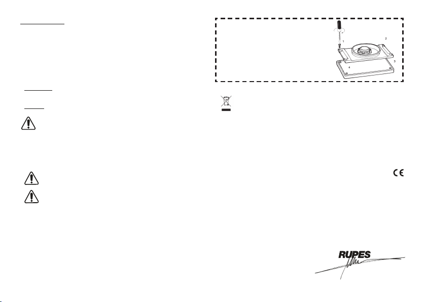
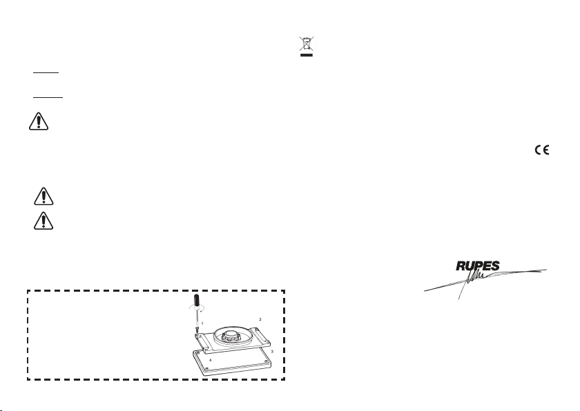
ATTENZIONE!
Per il buon funzionamento della
macchina si raccomanda,
dopo qualche ora di lavoro, di
serrare le 4 viti che stringono
la piastra base con la piastra
gomma.
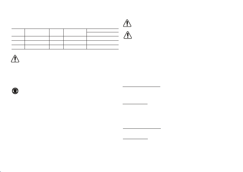
SSPF - SSCA
Livello di Pressione acustica / Potenza sonora Livello di vibrazioni su 3 assi
LPA LWA Incertezza ah Incertezza
dB(A) m/s2
SSCA 84 95 3 3,8 1,5
SSPF 84 95 3 3,8 1
Attenzione! i valori di misura indicati sono validi solo per utensili nuovi.
Nell’impiego quotidiano i valori di rumore e vibrazione cambiano.
2006/42/CE 2014/35/CE 2014/30/CE 2011/65/CE