6
2. Introduction
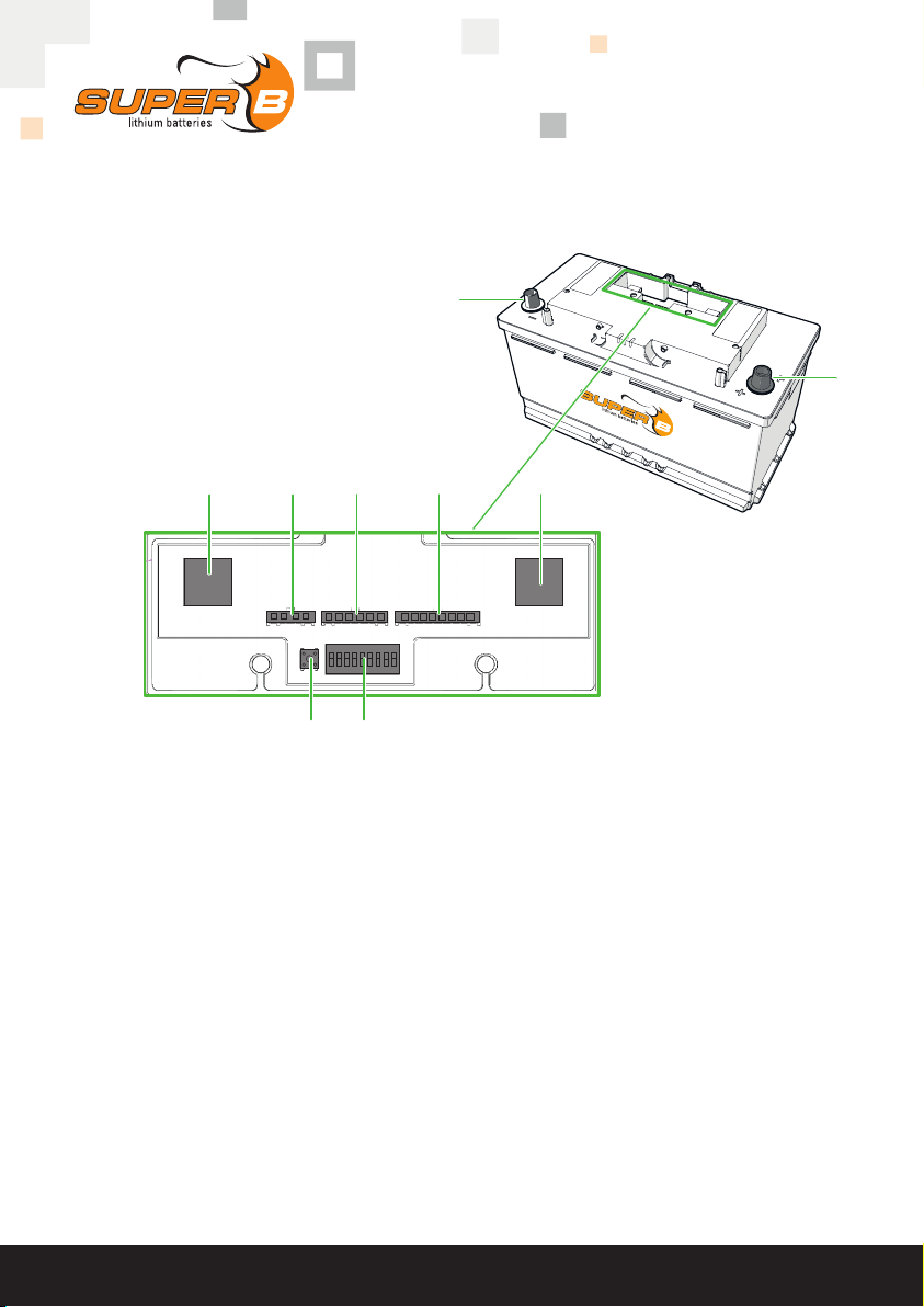
2.1. Product description
The Epsilon 12V90Ah is a Lithium Iron Phosphate rechargeable battery. The unique
combination of state-of-the art technology and smart software makes this Li-ion battery a
robust, safe and easy to use energy storage solution.
The Li-ion battery uses safe Lithium Iron Phosphate (LiFePO4) technology. With its integrated
battery management system (BMS) the Li-ion battery is protected from deep discharging,
overcharging and overheating. Eliminating the need for an external safety relay means the
Li-ion battery is very easy to install.
The Epsilon 12V90Ah Li-ion battery also has integrated battery monitoring which provides
details about its status such as voltage, current, temperature, state of charge and time
remaining. Hands-on monitoring is possible via Bluetooth, external monitoring devices and
LED indicators inform you about the actual status of your Li-ion battery.
2.2. Intended use
The Epsilon 12V90Ah Li-ion battery serves as a energy source of 12V in power systems
for recreational vehicles, commercial vehicles, leisure boats, commercial vessels and
stationary applications. Potential applications of this Li-ion battery include: off grid power
supply, marine power supply, medium for (renewable) energy storage and (traction) battery
for vehicles.Use as a starter battery is not possible. Never install multiple Li-ion batteries
in series. Up to 8 batteries can be connected in parallel to increase the total capacity up to
720Ah. For more Li-ion batteries in parallel always consult with Super B.
2.3. Glossary of Terminology
BMS: Battery Management System
Charge cycle: A period of use from fully charged, to fully discharged, and fully
recharged again
Endurance Life-cycle: The products maximum lifespan, achieved by following the guidelines
presented in this manual
LiFeP04 Lithium Iron Phosphate
SoC: State of Charge
CCCV Constant Current - Constant Voltage
DoD Depth of Discharge
Table 1. Glossary of terminology