SKF LAGD 1000 series User manual

SKF LAGD 1000
Instructions for use

2SKF LAGD 1000
Table of contents
EC Declaration of Conformity ..................................................................................4
Safety recommendations ..........................................................................................6
1. Description .....................................................................................................8
1.1 Application ...................................................................................................................... 8
1.2 Identification of parts .................................................................................................... 8
1.3 Designations ................................................................................................................... 9
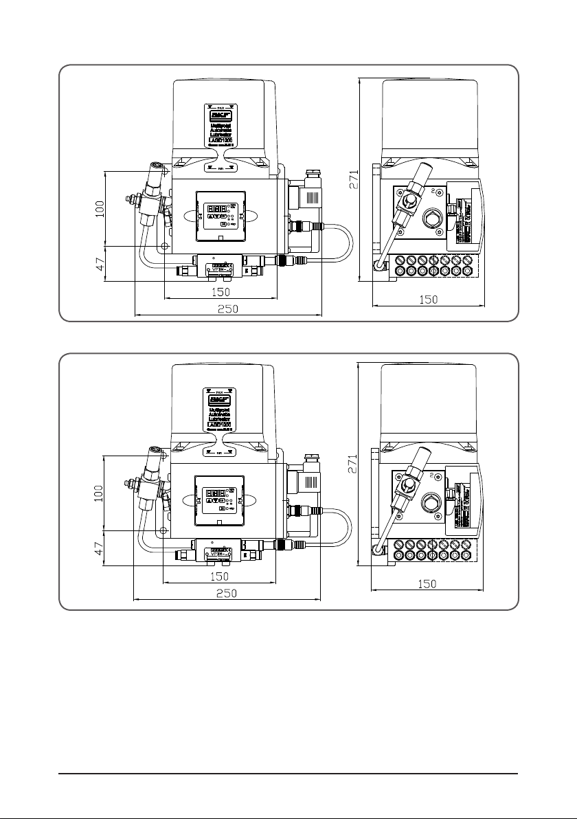
1.4 LAGD 1000 unit dimensions .....................................................................................10
2. Installation ...................................................................................................11
2.1 Preparation of lubrication points ...............................................................................11
2.2 Pump unit preparation................................................................................................12
2.3 Pump unit installation .................................................................................................13
2.4 Electrical connection ...................................................................................................14
2.4.1 Electrical specifications ..................................................................................14
2.4.2 LAGD 1000/DC ...............................................................................................14
2.4.3 LAGD 1000/AC ...............................................................................................15
2.5 Lubricant filling .............................................................................................................16
2.5.1 Suitability of greases .....................................................................................16
2.5.2 Compatibility of greases ................................................................................16
2.5.3 Initial filling of Lubricant ................................................................................16
2.5.4 Bleeding the system ......................................................................................17
2.5.5 Installation of lubrication pipes ....................................................................17
2.6 Level monitoring ..........................................................................................................19
2.6.1 Visual monitoring of level .............................................................................19
2.6.2 Level switch .....................................................................................................19
3. Selection of grease quantity for application ....................................................19
4. Operation of LAGD 1000/AC.. and LAGD 1000/DC.. units .................................20
4.1 LAGD 1000/AC.. & LAGD 1000/DC.. display and control unit ..............................20
4.1.1 Operation via push buttons ..........................................................................20
4.1.2 Three digit LED display .................................................................................21
4.2 Display mode for LAGD 1000/AC.. and LAGD 1000/DC .......................................22
4.2.1 Display of the operating values for LAGD 1000/AC.. & LAGD 1000/DC 22
4.3 Programming the LAGD 1000/AC.. and LAGD 1000/DC ......................................24
4.3.1 Changing the lubrication interval times ......................................................24
4.3.2 Programming sequence LAGD 1000/AC.. and LAGD 1000/DC ..............25
4.3.3 Changing the system monitoring.................................................................27
4.3.4 Changing the operating mode .....................................................................28
Original instructions

3SKF LAGD 1000
5. Faults ............................................................................................................29
5.1 Displaying faults ...........................................................................................................29
5.1.1 LAGD 1000/AC.. and LAGD 1000/DC.. faults ............................................29
5.1.2 Block operation ...............................................................................................30
5.1.3 Clearing the fault message ...........................................................................30
5.1.4 Storing the fault times ..................................................................................30
6. Maintenance and repair ..................................................................................31
7 Spare parts and accessories ...........................................................................31
8. Technical data ................................................................................................32
Original instructions

4SKF LAGD 1000
EC Declaration of conformity
We,
SKF Maintenance Products
Kelvinbaan 16
3439 MT Nieuwegein
The Netherlands
declare that the:
Multipoint automatic lubricators LAGD 1000 series
conforms to the essential protection requirements set out in the Directive(s) of
the Council for harmonization of the member states’ legal regulations.
• Electromagnetic compatibility 89/336/EEC through application of the
following (harmonized) European standards in respect to the Directive(s)
EMC89/336/EEC
61000-6-2
61000-6-3
• Electrical equipment tor use within certain voltage limits (Low-voltage
directive) 73/23/EEC through application of the following (harmonized)
European standards in respect to the Directive(s)
Low voltage 73/23/EEC
EN 60204-1
EN 60034-1
• This declaration certifies conformity with the aforementioned directives,
but does not contain any assurance of properties.
• The safety instructions in the documentation included with the product
must be observed.
• Operation of the products on non-standard mains voltage as well as
nonobservance of installation instructions can affect the EMC properties
and electrical safety.
• The certified products must not be started up until it is assured that the
machine, in which the product was installed, meets the provisions and
requirements of the directives to be applied.
In addition, the Multipoint automatic lubricators LAGD 1000 series
• Is in accordance with EC Machinery Directive 98/37/EC, Appendix 11B
intended for installation in a machine / for assembly with other

5SKF LAGD 1000
machinery to form a machine. Its startup is prohibited until conformity of
the overall machine has been established in accordance with the
appropriate accident prevention regulations, in particular in
implementation of the Use of Work Equipment Directive. The harmonized
standards applied here are, in particular DIN EN 809, DIN EN ISO
12100-1 and DIN EN ISO 12100-2.
• That as regards EC Pressure Equipment Directive 97/23/EC the unit may
only be used for its intended purpose and in accordance with the information
contained in the documentation.
The following must be observed in this connection:
• The products are neither designed nor approved for use in conjunction with
Group I fluids (hazardous fluids), as defined by Article 2, Par. 2 of Directive
67/548/EEC dated 27th June 1967.
• The products are neither designed nor approved for use in conjunction with
gases, liquefied gases, pressurized gases in solution, vapors and fluids with
a vapor pressure exceeding normal atmospheric pressure (1013 mbars) by
more than 0.5 bar at the maximum permissible temperature.
• When used as intended the products supplied by us do not reach the limit
values cited in Article 3, Par. 1, Number 1.1 to 1.3 and Par. 2 of Directive
97/23/EC. They are therefore not subject to the requirements set forth in
Appendix I of the Directive. They are consequently not provided with a CE
mark in respect to Directive 97/23/EC. They are classified by us in keeping
with Article, 3 Par. 3 of the directive.
Nieuwegein, the Netherlands,
December 2006
SKF Maintenance Products
Sébastien David
Manager Product Development and Quality

6SKF LAGD 1000
Safety recommendations
This symbol appears in the manual whenever it is necessary to
draw your attention to special dangers or important actions.
General
The components are designed and manufactured in conformity with the
generally accepted engineering standards as well as applicable industrial
safety and accident prevention regulations. Though constructed to meet
all relevant safety requirements, their use may still entail dangers leading
to personal injury of the user or third parties or damage to property.
Therefore, the components shall only be used when they are in a
technically perfect condition, the operating instructions having to be duly
observed. Any faults, in particular faults, which may affect safety, shall be
rectified without delay.
Use in conformity with intended purpose
The SKF Multipoint automatic lubricators LAGD 1000 are designed for
plant and machine lubrication. They are capable of delivering greases up
to NLGI grade 2. Any other use is not in conformity with the intended
purpose. They must not be used for vehicle lubrication applications.
Approved personnel
The components described in this manual may be installed, operated,
maintained and repaired only by competent personnel in accordance with
local statutory requirements.
Disclaimer of liability
SKF cannot be held liable for any damage caused by;
• Lack of lubricant,
• Contaminated or unsuited lubricants, installation of components or
spare parts other than genuine SKF components or spare parts,
• Any use which is not in conformity with the intended purpose,
• Inappropriate installation and filling, wrong electrical connection,
• Erroneous programming, improper reactions to malfunctioning,
• and non-observance of the instructions for use.

7SKF LAGD 1000
Installation work
When installing the LAGD 1000, the local accident prevention regulations
and the applicable operating and maintenance instructions must be
observed.
Danger caused by electrical current
The units must only be connected to the power supply by competent
personnel, in conformity with the local connection conditions and
regulations. Improperly connected equipment may lead to serious personal
injury and damage to property.
Danger caused by system pressure
The units may be pressurized. Therefore, they must be made pressure-less
before any extension work, modifications or repairs are carried out.
Grease reservoir
Take care when opening the grease reservoir cover. There is a strong
spring inside. The cover maybe ejected with force.
Plastic pipes
Protect all pipes against damage and excessive heat.
No other material shall be used than those permitted for this
type of unit. Any unsuitable material may cause a failure of the
unit and lead to serious injuries or property damage.
Lubricants
In general, the following lubricants can be used in LAGD 1000 series:
• Greases up to an NLGI grade of 2 with a maximum effective flow
pressure of ≤750 mbar (10.8 psi)
• Base oils of mineral ,synthetic and rapidly biodegradable type.
• Consistency adjustment and additives depend on the individual case.
However there are lubricants that have properties that make them
unsuitable for use in central lubrication units.
Synthetic lubricants, for example, may be incompatible with elastomers.
SKF provides the possibility to check the lubricants for their suitability for
central lubrication units. Consult the SKF specialists.
Transport and storage
In general, there are no limitations with respect to land, air or sea
transport.
Store in a dry place with a storage temperature between -40 °C & +70 °C
(-40 °C & 160 °F). Handle with care!

8SKF LAGD 1000
1. Description
1.1 Application
The SKF Multi-Point Lubricator LAGD 1000 can supply up to 20 lubrication points
(depending on variant) with a metered amount of lubricant (0,2 cm3). The LAGD 1000
can be power by AC or DC. The LAGD 1000 has a large 1 litre grease
reservoir that is supplied to a micro processor controlled pump unit. The pump is
programmed to operate for one or more cycles with a pause time in between. Each cycle
of the pump supplies grease to a progressive distributor that supplies a metered amount
of grease to the application, via pipes.
1.2 Identification of parts
1
2
6
7
8
3
4
5
Fig 1 Scope of delivery of the LAGD 1000

9SKF LAGD 1000
Item Quantity Description
1 1 pump unit
2 1 fitting material for the pump unit:
• 3 x M8 nuts
• 3 x M8 hexagon head screws
• 6 x washers for screws M8
Connection kit LAGD 1000-G
consisting of items 3-7:
1
3 50 m (164 ft) Plastic pipe
4 11 Straight connectors G1/8
5 11 Right angle swivel connectors G1/8
6 1 Connection bar
7 140 Cable tie
8 1 Pipe filling nipple
1.3 Designations
LAGD 1000 / voltage variants number of lube points
generic
designation
DC: 24V DC 10/12/14/16/18/20
AC: 115-240 AC 10/12/14/16/18/20
eg: LAGD 1000/AC16 is a LAGD 1000 with AC power with 16 outlets

10 SKF LAGD 1000
1.4 LAGD 1000 unit dimensions
Fig 2 LAGD 1000/DC.. dimensions
Fig 3 LAGD 1000/AC.. dimensions

11SKF LAGD 1000
2. Installation
General
The SKF Multipoint automatic lubricators LAGD 1000 are designed to lubricate plant and
machines. They must not be used for vehicle lubrication. They are capable of delivering
greases up to NLGI grade 2. The pump units differ in the way they can be electrically
connected as well as in number of lubrication points they can supply.
2.1 Preparation of lubrication points
Initially, check all lubricating points for possible damage and test the permeability by
means of a grease gun or a different lubrication device.
When operating new machines, fill any existing cavities in bearing points with a respective
lubricant. Otherwise, bearing damage may occur as a result of insufficient lubrication.
Remove the grease nipples at the lubricating points.
Screw in the supplied connectors (G1/8) to the lubricating points.
Ensure cleanness. Even minor contamination may result in system errors
or bearing damage.
Fig 4 Check the permeability of the lubricating points and fill any cavities in the bearing points.

12 SKF LAGD 1000
Fig 5 Remove the grease nipples.
Fig 6 Screw in the connector fittings.
2.2 Pump unit preparation
Connection with uneven number of lubricating points If the number of lubricating points
to be supplied is uneven, two of the outputs located at the distributor of the pump unit
have to be connected by means of the enclosed connection bar (Fig 7). This is necessary
for a proper distributor operation. To be able to screw in the connection bar, you first have
to remove two adjacent fittings on the distributor.
Then, screw in the connection bar.
No distributor output must be closed, as this would block the distributor.
When two outlets are connected by means of the connection bar, the
output flow from the connection bar is twice the volume of a single outlet.
Ensure cleanness. Even minor contamination may result in system errors
or bearing damage.

13SKF LAGD 1000
Fig 7 Connection bar for progressive distributors
2.3 Pump unit installation
The pump unit should be installed in a way which ensures protection against dirt, splash
water and vibration but also provides for easy access to make sure that all further
installation works can be carried out without difficulty and the unit can be easily refilled
later. The liquid level of the reservoir should be clearly visible. The unit must be installed in
vertical position.
For installation, the unit is equipped with a connection flange with three fixing points.
Mount the SKF Multipoint automatic lubricators LAGD 1000 to the machine with the three
supplied M8 bolts, washers and self-locking nuts (Tightening torque: 16 Nm, 11.8 ft.lbs).
The unit should be mounted in a position that is protected to the greatest possible extent.
Where holes have to be drilled for installation, position these holes as shown below, using
the template in Appendix 1.
When drilling the mounting holes, be aware of possible sources of danger,
such as available supply pipes, other units, non-stationary parts and heat
sources. Ask the machine manufacturer to confirm the position of the
mounting holes
Fitting with less than three screws is not allowed and may result in
breakage of the assembly flange.
The installation surface must be even. Otherwise the assembly flange may
be overloaded when tightening the screws and break.
Mount the unit at a safe distance from other items and conform to local
installation and accident prevention regulations.

14 SKF LAGD 1000
2.4 Electrical connection
Follow the information and instructions contained in this document and
the functional description of the respective control unit. Refer to the
safety recommendations (see section 1).
If the protective conductor connection is not properly made or damaged,
dangerous live voltages may occur on the unit!
The units must only be connected to the power supply by competent
personnel, in conformance with the local connection conditions and
regulations. Improperly connected equipment may lead to serious
personal injury and damage to property.
2.4.1 Electrical specifications
Item Rated
voltage
Typical power input
(load dependent)
Starting
current
(ca. 20 ms)
Back-up
fuse
LAGD 1000A/DC. 24 V DC 0,5 A ca. 1,4 A 3,0 A1
LAGD 1000A/AC. 230 V/50 Hz
230 V/60 Hz
115 V/50 Hz
115 V/60 Hz
0,45 A
0,66 A
1,0 A
1,3 A
-
-
-
-
2,5 A2
2,5 A
2,5 A
2,5 A
1 Fuse according to DIN 72581 T.3
2 Lead: Cross-section 1,5 mm2, length ≤12 m (39.4 ft)
2.4.2 LAGD 1000/DC
The LAGD 1000/DC is supplied with level monitoring as standard. One electrical power
connection is required.

15SKF LAGD 1000
Power connection to DIN EN 175 301-803 Plug supplied
Fig 8/9 LAGD 1000/DC Electrical connector position / LAGD 1000/DC Electrical connection diagram.
2.4.3 LAGD 1000/AC
The LAGD 1000/AC is supplied with level monitoring as standard. One electrical
connection is required.
Power connection to DIN EN 175 301-803 Plug supplied
Fig 10/11
LAGD 1000/AC Electrical connector position / LAGD 1000/AC Electrical connection diagram.

16 SKF LAGD 1000
2.5 Lubricant filling
All LAGD 1000 units are supplied unfilled.
2.5.1 Suitability of greases
The grease reservoir can hold up to 1 litre (33.8 US fl. oz) of grease, and the lubricator is
supplied empty. SKF greases LGFP 2, LGGB 2, LGWA 2 and LGHB 2 are recommended to
be used in LAGD 1000 lubricators at temperatures down to -10 °C (14 °F).
For temperatures down to -25 °C (-13 °F), SKF greases LGWA 2 and LGGB 2 are suitable.
Greases with graphite such as LGEM 2 aren’t suitable for the LAGD 1000. For all other
SKF greases please contact SKF.
2.5.2 Compatibility of greases
Check for grease compatibility. If filling with a different grease to that already used in
application, it is always best to remove as much of the old grease from the units and pipes
as possible.
2.5.3 Initial filling of Lubricant
The lubricator reservoir is filled in via the conical head lubrication nipple shown as A in
Fig. 12. This can be done using a filler pump or a grease gun. However, an air driven,
battery driven or electrical driven filler pump or grease gun is recommended for ease of use.
Fig 12 Position of grease nipples for filling and purging.

17SKF LAGD 1000
When the unit is filled for the first time, the lubricant forces the follower (rubber ring plate)
upward until the overfill outlet hole is reached. As filling continues, the air escapes until
the entire reservoir is filled with lubricant. When excess lubricant starts to emerge from
the overfill outlet, stop filling completely. When topping up, take care not to let lubricant
emerge from the overfill outlet hole. The levels (minimum and maximum) of the grease in
the container are shown by the rubber ring below the metal plate. Figure 13 clearly shows
the minimum, maximum and overfill details.
Fig 13 Position of grease filling marks
2.5.4 Bleeding the system
Connect the grease gun to the nipple shown as B in figure 12, and pump until the
lubricant emerging from the distribution block is free of air. The pressure relief valve is
used to protect the entire lubrication system against excessive internal pressures. The
valve is set to open at a pressure of 150 bars. If the operating pressure increases beyond
150 bars due to a blocked progressive feeder or lubricating point, the valve opens, and
grease visibly emerges from the valve.
2.5.5 Installation of lubrication pipes
Carefully cut the lubrication pipe to the correct lengths for the application.
1. Minimum level of grease
2. Grease
3. Maximum level of grease
4. Follower plate
5. Overfill outlet hole

18 SKF LAGD 1000
Fig 14 Shorten the plastic pipe
Use a grease gun to pre-fill the cut pipes. Firmly push the pipe into the open end of the
pipe filling nipple included with the lubricator. Connect the grease gun to the other end of
the filling nipple. Operate the grease gun to fill the pipe with grease. To remove the grease
filled pipe, push on the collar and at the same time pull out the pipe.
If the end of the pipe is damaged by the filling nipple, cut off the damaged end before you
connect the lubrication pipe to the divider block.
Push the pipes into the outlet of divider block. Lightly pull on each lubrication pipe to
ensure that a firm connection is made. The lubrication pipes can be routed.
Fix the lubrication pipes to suitable positions on the machine by means of the enclosed
cable ties. Cut the protruding ends of the cable tapes with scissors or a similar tool.
When routing the lubrication pipes, make sure that the pipes cannot be
bent, squeezed, sheared off nor rubbed through during operation.
Insert the pipes into the connectors fitted to the application. Lightly pull on each
lubrication pipe to ensure that a firm connection made.
Fig 15 Insert the plastic pipe into the fitting.
To detach the pipe, press the plastic pipe forcefully into the fitting and pull it out.

19SKF LAGD 1000
The lubrication pipes are made from black nylon that has a high bursting
strength. Genuine SKF pipes must be used. The grease can be pumped,
through the pipes, to a recommended distance of 6 meters depending on
environmental temperature (recommended ambient temperature
20 °C, 68°F)
2.6 Level monitoring
2.6.1 Visual monitoring of level
The transparent reservoir enables you to visually monitor the level. The level should be
checked at regular intervals for safety reasons. The current level can be precisely seen
from the position of the follower.
When the grease level in the reservoir drops below the “min” marking,
you must bleed the entire system. (see section 2.5.4)
TIP. If the grease level does not go below the “min” level, you do not need
to bleed the entire system.
2.6.2 Level switch
The SKF Multipoint automatic lubricators LAGD 1000 series are delivered with an
automatic level control function. When the level drops below the “min” marking, the
sequence of operations is stopped, and a fault message “FLL” appears in the display.
3. Selection of grease quantity for application
The SKF Dial Set CD ROM (MP3506) or LubeSelect for SKF greases
http://www.skf.com/portal/skf/home/aptitudexchange can be used to calculate the amount
of grease required over a given time period.
Example:
LubeSelect calculates the following grease requirement for a bearing over the relubrication
interval.
Grease L1 life (SKF re-lubrication interval), hrs 3800
Grease quantity replenish through lubrication holes, grams 155
Assuming that the grease has a specific density of around 0,9, the total amount of grease
required over the lubrication interval is 155/0,9 = 172 cm3
A complete internal cycle of the LAGD 1000 dispenses 0,2cm3 per outlet.
Therefore the number of cycles required is 172/0,2 =860 cycles
Over a period of 3800 hours, 860 cycles are required, that is: one cycle every 4,4 hours
(or two cycles every 8,8 hours and so on).
The LAGD 1000 can now be programmed accordingly, see section 4.3.2.

20 SKF LAGD 1000
4. Operation of LAGD 1000/AC.. and LAGD 1000/DC.. units
4.1 LAGD 1000/AC.. & LAGD 1000/DC.. display and control unit
A transparent plastic cover, to protect against water splashes and mechanical damage,
protects the display and control unit. To program or to display the current functions,
the cover has to be removed using a screwdriver. Replace the cover after use to protect
the unit.
Led display LAGD 1000/AC..
LAGD 1000/DC..
• Seven-segment display: Values and operating state
PAUSE
h/lmp
• Pause time
CONTACT
min/lmp
• Pump operation
CS • CMonitoring of system function by means of an external
cycle switch CS = Cycle Switch
PS • NOT USED FOR LAGD 1000. This LED must not light
FAULT • Fault message
Push buttons
• Turn on display
• Display values and parameters
• Call up the last parameter in the programming mode
• Set values and parameters
• Change between programming and display mode
• Confirm values
• Activate intermediate lubrication
• Clear fault message
Table of contents
Other SKF Test Equipment manuals