FAAC 565 User manual

ist umweltfreundlich
100% Altpapier
pour la nature
papier recyclé 100%
for nature
recycled paper 100%
per la natura
carta riciclata 100% para la naturaleza
100% papel reciclado
C
E
R
M
E
T
A
Z
I
E
N
D
A
C
E
R
T
I
F
I
C
A
T
A
UNI EN ISO 9001
-
085
565-570
575
565-570
575

13
ENGLISH ENGLISH
1) IMPORTANT! FAAC strongly recommends to follow these instructions
carefully for the safety of persons. Improper installation or misuse of
the product will cause very serious damages to persons.
2) Readtheinstructionscarefully beforeinstallingtheproduct.
3) Packagingmaterials(plastic,polystyreneetc.)areapotentialhazard
andmustbekeptoutofreachofchildren.
4) Keeptheseinstructionsforfuturereference.
5) This product has been designed and manufactured only for the use
statedinthismanual.Anyotherusenotexpresslysetforthwillaffectthe
reliabilityoftheproductand/orcouldbesourceofhazard.
6) FAAC S.p.A.cannot beheld responsiblefor anydamage caused by
improperuseordifferentfromtheuseforwhichtheautomationsystemis
destinedto.
7) Do not use this device in areas subject to explosion: the presence of
flammablegasorfumesisaserioushazard.
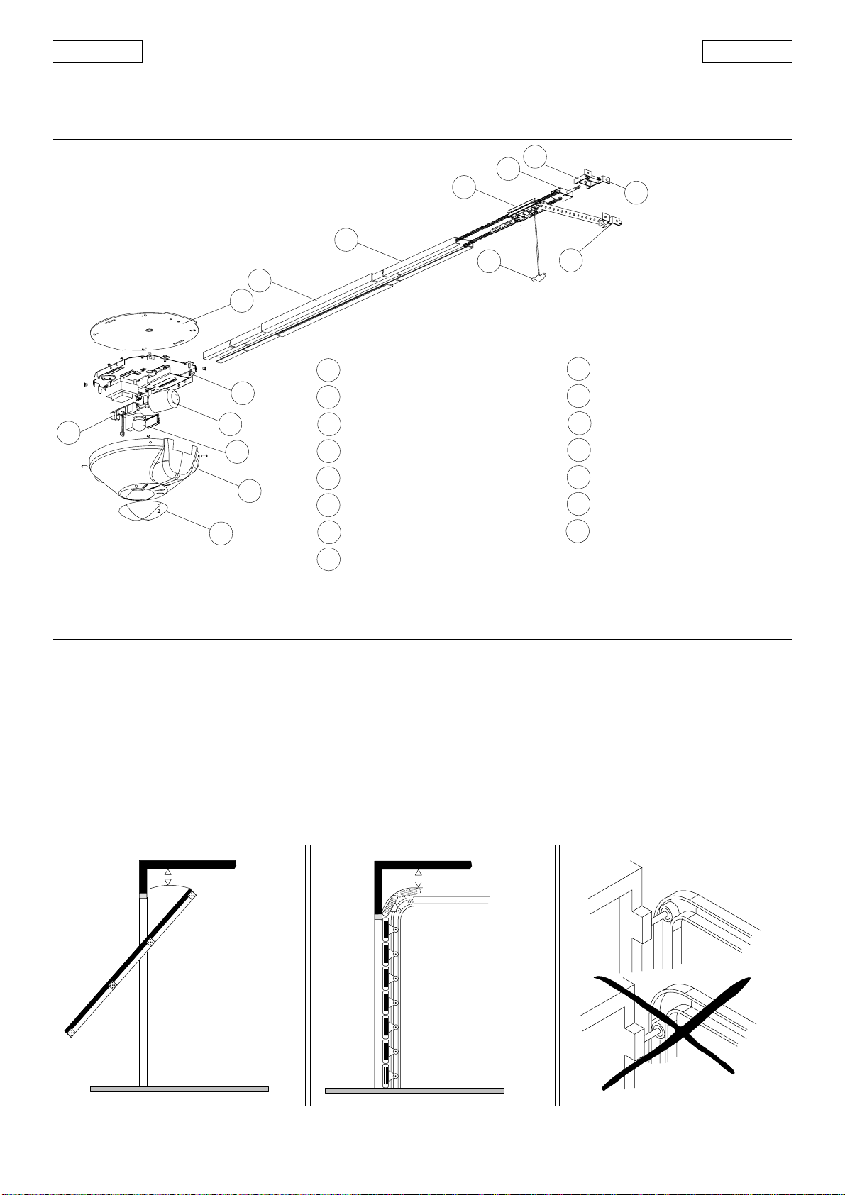
8) MechanicalconstructiveelementsmustcomplywithUNI8612,CENprEN
12604andCENprEN12605standards.
CountriesoutsidetheECshallfollowtheregulationsabovebesidestheir
nationalnormativereferencesinordertooffertheutmostsafety.
9) Faaccannotbeheldresponsibleforfailuretoobservetechnicalstan-
dardsintheconstructionofgatesanddoors,orforanydeformationof
thegateswhichmayoccurduringuse.
10) InstallationmustcomplywithUNI8612,CENprEN12453andCENprEN
12635.
ThedegreeofsafetyoftheautomationmustbeC+D.
10A) IEC335-2-95
11) Beforeattemptinganyjobonthesystemoroperator,cutoutelectric
poweranddisconnectthebatteries,ifinstalled.
12) Anomnipowerswitchshallbeprovidedfortheinstallationwithanopen-
ingdistance of thecontacts of 3 mm ofmore. Alternatively, usea 6A
EC MACHINE DIRECTIVE COMPLIANCE DECLARATION
(DIRECTIVE 89/392 EEC, APPENDIX II, PART B)
Manufacturer: FAAC S.p.A.
Address: Via Benini, 1 - 40069 Zola Predosa BOLOGNA - ITALY
Hereby declares that: the 565/570/575 automation system
• is intended to be incorporated into machinery, or to be assembled with other machinery to constitute
machinery in compliance with the requirements of Directive 89/392 EEC, and subsequent amendments 91/
368 EEC, 93/44 EEC and 93/68 EEC;
• complies with the essential safety requirements in the following EEC Directives:
73/23 EEC and subsequent amendment 93/68 EEC.
89/336 EEC and subsequent amendments 92/31 EEC and 93/68 EEC.
and furthermore declares that unit must not be put into service until the machinery into which it is incorporated
or of which it is a component has been identified and declared to be in conformity with the provisions of
Directive 89/392 EEC and subsequent amendments enacted by the national implementing legislation.
Bologna, 1 January 1999 Managing Director
A.Bassi
thermomagneticbreakerwithmulti-poleswitching.
13) Ensurethatthereisadifferentialswitchup-lineoftheelectricalsystem,
withatripthresholdof0.03A.
14) Checkthattheearthingplantisinperfectconditionandconnectitto
themetallicparts.Alsoearththeyellow/greenwireoftheoperator.
15) Theautomationisfittedwithananti-crushsafetysystemthatisatorque
controldevice.Inanycase,furthersafetydevicesshallbeinstalled.
16) Thesafetydevices(e.g.photocells,safetyedges,etc.)protectareas
wherethereisa mechanicalmovementhazard,e.g.crushing,entrap-
mentandcutting.
17) Eachinstallationmustbefittedwithatleastoneflashinglight(e.g.FAAC
LAMP,MINILAMP,etc.)aswellasawarningplatesuitablyfixedtothe
gate,besidesthesafetydevicesasperpoint16above.
18) Faaccannotbeheldresponsibleregardingsafetyandcorrectfunction-
ingoftheautomationintheeventthatpartsotherthanFaacoriginal
partsareused.
19) UseonlyFaacoriginalsparepartsformaintenanceoperations.
20) Donotcarryoutanymodificationstoautomationcomponents.
21) Theinstallermustsupplyallinformationregardingmanualoperationof
thesystemintheeventofanemergencyandprovidetheend-userwith
the”End-userGuide”attachedtotheproduct.
22) Donotallowchildrenoradultstostandneartheproductduringopera-
tion.
23) Keepoutofreachofchildrentheremoteradiocontrolsandanycontrol
devices.Theautomationcouldbeoperatedunintentionally.
24) Theend-usermustavoidanyattempttorepairoradjusttheautomation
personally.Theseoperationsmustbecarriedoutexclusivelybyqualified
personnel.
25) What is not explicitly stated in these instructions is not permitted.
IMPORTANT NOTICE FOR THE INSTALLER
GENERAL SAFETY REGULATIONS

14
ENGLISH ENGLISH
AUTOMATIC SYSTEM 565/570/575
Theseinstructionsapplytothefollowingmodels:
565 - 570 - 575
Automaticsystems565-570-575aredesignedtoautomateover-
headspring-balanced,sectional,andcounterbalanced(with
specialGDA3000accessory) doorsforresidentialgarages.
Theyconsistofanelectro-mechanicaloperator,electroniccon-
trolapplianceandcourtesylampbuiltintoasingleunit. Theunit
is fitted to the ceiling and opens the door by means of a
transmissionchain.
The system is non-reversing and, therefore, the door locks me-
chanicallywhenthemotorisnotoperatingand,consequently,
nootherlockisnecessary;twomanualreleasesontheinsideand
outside(optional)makeitpossibletomovethedoormanuallyin
case of a power cut or fault.
Any obstacles are certain to be detected by a controlling
electronicdevicewhichcomesintoactionwhiletheautomatic
systemisinoperation.
The565-570and575automatedsystemsweredesignedandbuilt
forindooruseandforcontrollingvehicleaccess.Avoidanyother
use.
2.DIMENSIONS
Fig.1
Fig.2
Power pipe (230V)
Cable 4 x 0,5 (RX photocell)
Cable 3x0.5 (Radio receiver)
Cable 2 x 0,5 (TX photocell)
Low voltage pipe
Cable 2 x 1.5 + earth (power supply)
3. ANCILLARY ELECTRICAL EQUIPMENT
1. DESCRIPTION AND TECHNICAL SPECIFICATIONS
328 157
415
2738(565)/3338(570)/3938(575)
Dimensionsinmm
MODEL 565 570 575
Power supply 230V ac 50Hz
Electric motor 24V dc
Maximum absorbed power 220W
Maximum cycles per hour 20 (with load of 56Kg at 20°C)
Maximum consecutive cycles 6 (at 20°C)
Minimum distance from ceiling 35mm (Fig.4 and 5 )
Maximum available travel 1900mm 2500mm 3100mm
Pulling/thrust power 1200N (~120Kg)
Courtesy light 230V ac 40W max
Courtesy light timer 2 minutes
Carriage speed (load free) 12 cm/sec.
Deceleration speed 6 cm/sec.
Deceleration travel Varies according to setup
Internal safety device Type 2
Response time of built-in safety 150msec
device
Door max width 3000 mm (5000mm sectional)
Door max height See max available travel
Protection class IP20
Ambient temperature -20 / +55°C
12
3
4
5
6

15
ENGLISH ENGLISH
3.DESCRIPTION
4. PRELIMINARYCHECKS
Thestructureofthedoormustbesuitableforaccommodatingautomation.Inparticular,checkthatthedoordimensionsconform
tothose indicatedin thetechnical specifications,and thatthe dooris sufficientlysturdy.
Checktheefficiencyofthedoorbearings and joints.
Makesurethedoorisfreeofanyfriction;ifnecessary,cleantheguidesandoilthemwithsiliconelubricant,butdonotuse grease.
Removethedoor’sexistingclosingmechanismtoensurethedoorisclosedbytheautomaticsystem.
Checkifan efficientearth plateisavailablefor electricalconnectiontothe operator.
Makesure there isa clearanceof atleast 35 mmbetween theceiling andthe highest sliding point ofthe door(fig.4 and5).
Fig.4 Fig.5 Fig.6
Inthecaseof sectionaldoors,checkthattheupperguiderollerisinthehorizontalpartoftheguidewhenthedoorisclosed(fig.6).
Fig.3
1
10
9
8
7
6
53
2
13
12
11
3
4
14
15
1
2
3
4
5
6
7
9
10
11
12
13
14
815
CEILINGFIXTURE
MOTORUNIT
ELECTRONICEQUIPMENT
COURTESYLIGHT
PROTECTIVEHOUSING
SLIDINGGUIDE
DUST-GUARD RELEASEKNOB
DRIVEBRACKET
FRONTSECURINGBRACKET
FRONTFLANGE
TRANSMISSIONPULLEY
DRIVECARRIAGE
MOTOR UNIT SUPPORT
CENTRALSLIDE
min. 35 mm
min. 35 mm

16
ENGLISH ENGLISH
Fig.10 Fig.11
5.OPERATORASSEMBLY
N.B.: Screws and expansion plugs for securing the operator to the infrastructure are not supplied.
5.1Ifusingtheoutsidereleasedevice(optionalitem),withdrawthecarriagefromtheguide,andfitthecableintheappropriateseat
on the carriage, as shown in figure 7.
5.2 Fittheguide(Fig.8ref.B)intheslide(Fig.8ref.C),centrallywithrespecttotheslide.Pre-formthebracketsandsecurethemtothe
guidewith thenut (Fig.8).
5.3Insertthelongitudinalmember withchaininthe centralslide(fig.9) untilitmeetsthe metalprojection(fig.8 ref.D).
5.4Fitanewlongitudinalmember(fig.10)inthealreadyinstalledunit,makingsurethatthemetalprojectionshowninFig.8ref.Acomes
intocontact withthecentral slide.
5.5Removethehousing,unscrewthelampand,usingasuitablewrench,removethenutssecuringthemotorunittotheoperator
(fig.11).
Fig.9
Fig.8
Fig.7
A
D
B
C

17
ENGLISH ENGLISH
5.10Fitthe flangeintotheslidingguide,securingitwiththetwo
suppliedM5Allenscrews(fig.14),andapplytensiontothechain
withthenut(fig.14).
5.11Positiontheoperatorontheground,verticallyrespecttofloor
(fig.15ref.A).
5.12Checkchaintension,makingsurethatthesedistancesare
equal(asshowninfig.15ref.B):lowerchain-upperchain;upper
chain - upper rail joint.
5.13Adjustchaintensionifnecessary,usingthenutasindicated
infig.15ref.C.
N.B. : To apply tension to the chain, turn the nut clock - wise.
To slacken the chain, turn the nut anti clock - wise
Warning:toomuchchaintensioncoulddamagethemotorunit.
5.6Offertheassembledguidetotheoperator.
5.7 Lift up the motor unit, taking care not to damage the control board, couple the chain to the pinion gear (fig.12).
5.8Locatethedriveunitonthesupport,securingitwithappropriateself-tappingscrews(Fig.13ref.A).Fitthelongitudinal member
asin figure 13(ref.A)to itsstoppoint.
5.9Tightenthe driveunitwith theappropriate wrench(fig.13 ref.B).
Fig.12 Fig.13
Fig.14
B
C
A
Fig.15
A
B

18
ENGLISH ENGLISH
6.INSTALLATION
6.1 Find the mid-point of door and ceiling and mark the two lines with a highlighter.
6.2 Find the highest movement point of the door and mark this on the lintel.
6.3Positionthesecuringbracket5mmabovethelineyouhadmarked,whichmustbe centered with respecttothedoor(fig.16).
6.4Mark thetwo bracketsecuring pointsand drill thenecessary holes.
6.5Next,usingscrewsandwashers, screw thebracket on theexpansion plugs (fig.16).
Fig.19
6.6Place theoperatoron theground,lift upthe slidinglongitu-
dinalmember andsteptoward thebracket– fitthe screwand
tightenthenut(fig.17).
6.7Lift upthe operator, makingsure itis horizontalwithrespect
to the door – use a spirit level.
6.8Whenyouhave reachedthe correctposition, measurethe
distancebetweenceilingandoperatorsothatyoucanshape
thesecuring brackets inadvance.
6.9Fitthesuppliedbracketsintheslotsandsecuretheoperator
withthe nut(fig. 18).
6.10Bend the securing brackets inline withthe measurements
you had taken (fig. 19).
6.11Liftuptheoperator,placeitinitscorrectposition,andmark
thesecuringholes.
6.12 Drill, insert the expansion plugs and, using screws and
washers,securethemotorunittotheceiling(fig.20ref.A).
6.13Firstestablishtheheightofthereleaseknob,cutoffexcess
cord, and make a knot on the cord end.
Fig.16
Fig.17
6.14 Place the knot inside the knob – as shown in fig. 20 ref. B –
andclose it.
6.15Ifusingthecentralsupportguide,shapethebrackets,lock
them with a nut and secure them to the ceiling (fig. 21).
Fig.18
Fig.20
5 mm
A
B

19
ENGLISH ENGLISH
6.16Forsectionaldoors,seepoint6.25.
6.17 Secure the attachment to the drive shaft, using a suitable screw and nut (fig. 22).
6.18Releasetheoperator,bypullingthereleaseleverdownward(fig.23).
6.19Closetheoverheaddoor.
6.20Takethereleased carriageto theclosingpoint.
6.21 Rest the attachment on the door, in a central position with respect to the mid-line you had marked out.
N.B.:Thedistancebetweendrivebracketandslidingrailbracketmustnotexceed20cm(max30°)(fig.24).
6.22Checktheposition,drillandsecurewithsuitablescrews(fig.24).
Fig.25 Fig.26
6.23Re-locktheautomaticsystembypullingthehandlesideways(fig.25)N.B.:onrelease,makesureyoucanseethered“LOCK”
indicationwindowunderthe carriage– thismeans itwas correctlyreset.
6.24 Important: slide the door along the rail to re-locate the hook-up point.
6.25For sectionaldoors thatrequire it, fitthe armshown infigure 26 ref.A onthe attachmentand carryonfrom point6.18.
Fig.21 Fig.22
Fig.23 Fig.24
20 cm
LOCK
A

20
ENGLISH ENGLISH
7.CONNECTION OF565MPS ELECTRONICCARD
IMPORTANT:Beforeattemptinganyworkonthecard(connections,programming,maintenance),alwaysturnoffpower.
Observepoints 10, 11,12,13 and14ofthe GENERALSAFETYRULES.
Observingtheindicationsinfig.2,installtheracewaysandmaketheelectricalconnectionsfromthe565MPSelectronicappliance
totheselectedaccessories(fig.28).
Alwaysseparatepowercablesfromcontrolandsafetycables(push-button receiver,photocells,etc.). Topreventanyelectricnoise
whatever,useseparatesheaths.
TECHNICALSPECIFICATIONS
565MPSCARDCOMPONENTS
F1 Fuse for transf. primary winding, 1A
F2 Motor fuse, 10A
F3 Fuse for 0,5A accessories output
J1 Low voltage terminal board for inputs /accessories
J2 Rapid connector for decoding/RP receivers cards
J3 230V power supply input terminal board
J4 Connector for transformer primary winding
J5 Courtesy light connector
J6 Flashlight output terminal board
J7 Connector for transformer secondary winding
J8 Motor output connector
P1 Open push-button
P2 Set-up push-button
LK1 Enable/disable fail-safe
LK2 Varies sensitivity of reversing device Fig.27
fail-safe enabled fail-safe disabledLK1=
reversing sensitivity
150N (~15Kg)
LK2= reversing sensitivity
300N (~30Kg)
DESCRIPTION
TERMINALBOARDJ1(lowvoltage)
OPEN=OpenCommand(N.O.)
Anydevice(push-button, detector,…)which,byclosing acontact,suppliesan opening(orclosing) pulse tothedoor.
Toinstall several Opendevices,connect N.O.contactsin parallel.
STOP=Stopcommand(N.C.)
Anydevice (e.g.a push-button)which, byopening acontact, stopsdoor movement.
Toinstallseveralstopdevices,connecttheN.C.contactsinseries.
N.B.:ifstopdevicesarenotused,jumper connect STOP to the inputs common contact.
=input/negativeaccessoriessupplycommoncontact.
=Accessories supplypositivepole(24Vdc200mAmax)
FSW=Closingsafety-devicescontact(N.C.)
Safetydevicesarealldevices(photocells,sensitiveedges,…)withN.C.contact,which,ifthereisanobstacleintheareathey
protect,operatetoreversedoorclosingmovement.
Ifthe safety devicesare activated whenthe door islockedor open,theyprevent itfromclosing.
Toinstallseveralsafetydevices,connecttheN.C.contactsinseries.
N.B.:if safety devices are notconnected,jumperconnectFSW to the inputscommoncontact.
-FSWTX=Terminalforconnectionofthe negative pole (-)ofthephotocellstransmitter(TX).
CONNECTORJ2(lowvoltage)
ConnectorJ2isused for rapidconnection ofMINIDEC, DECODER,and RPRECEIVER cards.
Insertandremovethecardsaftercuttingpower.
+
-
R
565 MPS
J1
J2
J7
J8
J6
J5
J4
J3
P2
P1
F2
LK1
LK2
F1
F3
Power supply voltage 230V ac 50Hz
Power supply for accessories 24Vdc
Accessories max. load 200 mA
Ambient temperature -20°/+55°C
Fuses transf./motor primary
winding
Quick-fit connector for decoding cards and
RPreceivers
Function logics Automatic/Semi-
automatic
Terminal board connections Open/Stop/Safety
devices/Fail-
safe/
Flashlight

21
ENGLISH ENGLISH
TERMINALBOARDJ3(highvoltage)
Terminalboard forpower supplyof 230V ~50Hz(F=phase N=neutral)
Connectthesystem’s earthwiretothededicatedterminal(seeIDsticker–fig.31ref.A).
TERMINALBOARDJ6(highvoltage)
230V~Terminalboardforconnectionofflashlight.
LK1 JUMPER (enable/disable fail-safe)
The565MPScardhasanothersafetydevice–theFAIL-SAFE–which,priortoanyactivation,controlsiftheN.C.contactonthe
photocellreceiver(fig.27)isoperatingefficiently.
JUMPERLK2(150N/300N)
Servestovarythesensitivityofthereversingdevice(fig.27).
Fig.28
8.ANTENNAINSTALLATION(OPTIONAL)
8.1IfyouareusinganRPreceiver,andwishtoincreaseitsrange,youcanuseanexternal433MHZantenna(antennaconnection
instructionsareon the rearoftheRP receiverblister-pack).
8.2 Pick up the housing and, using an appropriate bit, drill from the inside outward in the guided area (fig. 29).
8.3 Turn the housing toward the front, fit the antenna and secure it from the inside with a suitable nut (fig. 30).
Fig30Fig.29
Ø10
J1
J2
RP - DECODER
LK2
LK1
FAIL SAFE
OPEN STOP TX
FSW
FSW
C3
J7
J8
P1
OPEN
P2
SETUP
J3 J4 J6
J5
PRIM.TF. LIGHT
R
565 MPS
230V ac 50Hz FAAC LAMP
••
••
1
2
••
2
1
3
4
5
•
•
•
RX
TX
OPEN
STOP
OTHERSAFETYDEVICES

22
ENGLISH ENGLISH
9.CONNECTIONS
9.1 Connect the power cable, as shown in figure 31, securing it with a clamp in the indicated area.
9.2Fitthescrewintheappropriateseatandtightenwithwasher
andnut(fig.31ref.A).
9.3 Position the earth eyelet on the screw, add a washer and
tightenwitthe nut(fig.32ref.A).
9.4Ifyouareusingtubesleevestosecurethecables,makeaslot
asshowninfigure32.
9.5Screw thelamp inthe appropriatelamp-holder.
9.6 Securetheoperatorhousingusingappropriatescrews(fig.33).
Fig.31
Fig.32
Fig.33
To accesstheprogramming push-button, dismantlethecour-
tesylightceilingfixture,unscrewingtheappropriatescrew.
Slidetheceilingfixtureinthedirectionshownbythearrow(fig.34).
SET-UP CYCLE
During this procedure, the obstacle detection and Fail-safe
deviceareNOToperating.
Theset-upcycledefines:
-anti-crushingsafetylevelsduringopeningandclosing
-decelerationpoints
-doorcompleteopeningand closing point
- pause time
Thisprocedurecanbecarriedoutatanytime,withtheoperator
inanyposition,bymeansoftheset-uppush-button(seedifferent
set-upmodes).
Set-upoccurswithamax.forceof800N.Iftheforceisnotsufficient
to complete the learning, it can be increased to 1200N by
activating,duringthe800Ncycle,a second set-upprocedure
(by pressing the set-up push-button again as indicated in the
differentmodes).
Twofunctionlogics areavailableon thisappliance:
AUTOMATIC(TABLE1)
SEMI-AUTOMATIC(TABLE2)
10.PROGRAMMING
Fig.34
A
A
A

23
ENGLISH ENGLISH
FUNCTIONLOGICS
* Prevents closing if pulse is maintained
* Prevents closing and/or opening if pulse is maintained
Table1AUTOMATICLogic
CLOSED
OPEN
CLOSING
LOCKED
OPENING
Closes
Open
Reversesmotion
Locks
Closes
STOPOPEN SAFETY DEVICES
Noeffect**
Locks **
Locks **
Noeffect**
Noeffect
Reversesmotion
Noeffect *
Noeffect *
OVERHEAD
DOOR
Noeffect** Noeffect*
Table2SEMI-AUTOMATICLogic
CLOSED
OPEN FOR
PAUSE
CLOSING
OPENING
Opensand
closes afterthe
pausetime
Closes
STOPOPEN SAFETY DEVICES
Noeffect**
Locks*
Locks **
Locks **
Noeffect**
Noeffect
Restartspause
timecount*
Reversesmotion
Noeffect *
Noeffect *
OVERHEAD
DOOR
LOCKED
Reversesmotion
Restartspause
timecount*
Noeffect
AUTOMATICSET-UP
Theset-upprocedureisexecutedautomaticallyjustwithapulse.
MANUALSET-UP
Thisprocedureenablesyoutoselectthedecelerationpoints,the
fully open point, and pause time.
AUTOMATICSET-UPWITHLOGIC“E”(SEMI-AUTOMATIC)
Pressand release theSET-UP push-buttonto selectthe logic.
After8secondstheoperatoreffectsaclosingoperationuntila
stop is detected.
Theoperatornowopensthedoor,andtheopeningmovement
finisheswhenthemechanicalstopisrecognised.
Thedoorisimmediatelyclosed.
Theelectronicapplianceestablishesthedecelerationpoints.
IftheSETUPprocedurewassuccessful,thecourtesylampstays
lightedfor5seconds.Duringthistime,inordertoreducetheload
onthereleasesystem,openpulsescanbesentwithin2seconds
of each other to reverse the release carriage. A pulse equals
travelof5millimetres.
N.B.: the carriage can be seen to reverse only when the auto-
matedsystemisoperatingnormally.
MANUALSET-UPWITHLOGIC“E”(SEMI-AUTOMATIC)
PressandreleasetheSET-UPpush-buttontoselectthelogic.Carry
outthefollowingprocedurewithin8secondsafterpressingthe
SETUP push-button, otherwise the oprator will execute auto-
maticSETUP.
1st OPEN:theoperatoreffectsaclosingoperationuntilastopis
detected.
2ndOPEN:theoperatorcontinueswithanopeningmovement.
3rd OPEN: defines the point at which start of deceleration is
required.
4thOPEN: definestheend oftheopening** movement.
5thOPEN: startsclosingmovement.
6th OPEN: defines the point at which start of deceleration is
required.
Allowthe operatorto reachthe stop.
IftheSETUPprocedurewassuccessful,thecourtesylampstays
lightedfor5seconds.Duringthistime,inordertoreducetheload
onthereleasesystem,openpulsescanbesentwithin2seconds
of each other to reverse the release carriage. A pulse equals
travelof5millimetres.
N.B.: the carriage can be seen to reverse only when the auto-
matedsystemisoperatingnormally.
AUTOMATICSET-UPWITHLOGIC“A”(AUTOMATIC)
Hold down the SET-UP push-button to select the logic until the
courtesylightgoeson(about5seconds).
After8secondstheoperatoreffectsaclosingoperationuntila
stop is detected.
Theoperatornowopensthedoor,andtheopeningmovement
finisheswhenthemechanicalstopisrecognised.*
Thedoorisimmediatelyclosed.
The electronic appliance establishes the deceleration points,
and pause time is fixed at 3 minutes.
IftheSETUPprocedurewassuccessful,thecourtesylampstays
lightedfor5seconds.Duringthistime,inordertoreducetheload
onthereleasesystem,openpulsescanbesentwithin2seconds
of each other to reverse the release carriage. A pulse equals
travelof5millimetres.
N.B.: the carriage can be seen to reverse only when the auto-
matedsystemisoperatingnormally.
MANUALSET-UPWITHLOGIC“A”(AUTOMATIC)
Hold down the SET-UP push-button to select the logic until the
courtesylightgoeson(about5seconds).Carryoutthefollowing
procedurewithin8secondsafterpressingtheSETUPpush-button,
otherwisetheopratorwillexecuteautomaticSETUP.
1st OPEN:the operatoreffects aclosing operationuntil a stopis
detected.
2ndOPEN:theoperatorcontinueswithanopeningmovement.
3rd OPEN: defines the point at which start of deceleration is
required.
4thOPEN:definestheendoftheopeningmovementandstarts
thepause time count**(3 minutesmax.).
5thOPEN:interruptsthepausetimecountandstartstheclosing
movement.
6th OPEN: defines the point at which start of deceleration is
required.
Allowthe operatorto reachthe stop.
Ifthe SETUPprocedure wassuccessful, thecourtesy lampstays
lightedfor5seconds.Duringthistime,inordertoreducetheload
onthereleasesystem,openpulsescanbesentwithin2seconds
ofeachothertoreversethereleasecarriage.Apulseequalstravel
of5millimetres.
N.B.: the carriage can be seen to reverse only when the auto-
matedsystemisoperatingnormally.
* Otherwise, an OPEN pulse may replace the stop.
** Otherwise, the stop can be used during opening.
IMPORTANT:Atset-up,iftheoperatordoesnoteffectanymove-
ment when the OPEN push-button (see fig.34 ref. A) is pressed,
check that the housing is in correct position.

24
ENGLISH ENGLISH
Fig.37Fig.36
Fig.39Fig.38
•Twoexternalreleasesystemscanbefitted:
-withhandle(fig.38ref.A)
-withwrench(fig.38ref.B)
•Counterbalanced doors can be automated byusing theaccessory shownin fig.39 (GDA 3000).
RELEASE
DEBLOQUER
ENTRIEGELN
DESBLOQUEAR
SBLOCCARE
LOCK
RE-LOCK
BLOQUER A NOUVEAU
WIEDER BLOKIEREN
BLOQUEAR DE NUEVO
RIBLOCCARE
WARNING
Fig.35
Wheninstallationhasbeencompleted,check the efficiency
of the automated system and safety devices, and then
applythe “danger”warning sticker(fig.35) onthe panel of
the up-and-over door to make it easy to see.
Applythesticker, whichindicatesthe releasedevice ofthe
automatedsystem(fig.35).
11.OPTIONALACCESSORIES
• If you are using the card for the CN60-E Sensitive Edge, a
compartmentisprovidedforitinsidetheoperatorhousinginthe
positionshowninfigure36.
•Floatingbatteriesinstallationprocedure:fitthemontheopera-
torwith the appropriate bracket, andsecure themwith screw
and nut in the position shown in figure 37.
ATTENTION!Ifreplacingbatteries,cutoutelectricalpower
beforeattemptinganyoperation.
A
B

USER’S GUIDE
AUTOMATIC SYSTEMS 565-570-575
Readthe instructions carefullybefore using theproduct andstore them forfuture use.
GENERALSAFETYREGULATIONS
Ifcorrectlyinstalledandused,565-570-575automaticsystemsensureahighdegreeof
safety.
Somesimplerulesonbehaviourcanpreventaccidentaltrouble:
- Do not, under any circumstances, stand under the overhead door.
-Donotallowchildren,personsorthingsneartheautomaticsystems,especiallywhile
theyareoperating.
-Keepremote-controls,orotherpulsegeneratorsthatcouldopenthedoor,wellaway
fromchildren.
- Do not allow children to play with the automatic system.
-Donotwillinglyobstructdoormovement.
-Preventanybranchesorshrubsfrominterferingwithdoormovement.
-Keep theindicator-lights efficientand easyto see.
- Do not attempt to activate the door by hand unless you have released it.
- In the event of malfunctions, release the door to allow access and wait for qualified
technicalpersonneltodothenecessarywork.
-Whenyouhavesetmanualoperationmode,cutpowertothesystembeforerestoring
normaloperation.
- Do not in any way modify the components of the automation system.
- Do not attempt any kind of repair or direct action whatever and contact qualified
FAACpersonnelonly.
- At least every six months: arrange a check by qualified personnel of the automatic
system,safetydevicesandearthconnection.
DESCRIPTION
Automaticsystems565-570-575aredesignedtoautomateoverheadspring-balanced,
sectional,counterbalanced(withspecialGDA3000accessory)doorsforresidential
garages.
Theautomaticsystemsconsistofanelectro-mechanicaloperator,electroniccontrol
appliance, courtesy lamp and protection housing built into a single unit.
Thesystemisnon-reversingand,therefore,thedoorlocksmechanicallywhenthemotor
isnotoperatingand,consequently,nootherlockisnecessary;amanualreleasemakes
it possible to move the door in case of a power cut or fault.
Anelectronicdeviceensuresthatany obstacles aredetected.
The door is normally closed; when the electronic control unit receives an opening
commandfromtheremotecontrol,orfromanyothertypeofpulsegenerator(fig.1),it
activatesthe electric motorwhich, by meansof a transmissionchain, pullsthe door
opentoallowaccess.
-If the automatic mode was set, the door closes automatically after pause time has
elapsed.
Anopeningpulsesuppliedduring opening hasno effect.
-If the semi-automatic mode was set, a second pulse must be sent to close the door
again.
Anopeningpulsesuppliedduringopeningstopsmovement.
Anopeningpulsesuppliedduringre-closing,alwayscausesmovementtobereversed.
Astoppulse(ifsupplied)always stops movement.
Forfulldetailsofdooractivityinthedifferentlogics,consulttheinstallationengineer.
Automaticsystemsmayincludesafetydevices(photocells)thatpreventthedoorfrom
closing when there is an obstacle in the area they protect.
Emergencymanualopeningispossiblebyusingthereleasesystem.
Thewarning-lightindicatesthatthedooriscurrentlymoving.
Thecourtesylightisactivatedwhenthemotor startsandcontinuesforabout2minutes
afteritstops.
MANUALOPERATION
The565-570-575operatorsareequippedwithanemergencysystemactivatedfromthe
inside–however,alockcanbefittedonrequest,foractivatingreleasefromtheoutside.
If the door has to be moved manually due to a power cut or a fault of the automatic
system,usethereleasedeviceasfollows:
-Releasetheoperator,bypullingthereleaseleverdownward(fig.22ref.A).
RESTORINGAUTOMATIC OPERATIONMODE
Re-locktheautomaticsystembypullingthehandlesideways(fig.2ref.B):
N.B.:onrelease, make sureyoucansee thered “LOCK”indicationwindowunder the
carriage–thismeansitwascorrectlyreset.
Important: slide the door along the rail to re-locate the hook-up point.
LAMPREPLACEMENT (fig.3)
Toreplacethelamp,unscrewandremovetheceilingfixturesupportscrew.
Slidetheceilingfixtureinthedirectionshownbythearrow(fig.33).
Replace the lamp (220Vac , 40W max.).
Fig.2
Fig.3
Fig.1
A
B
LOCK
RELEASE
RE-LOCK


Timbro del Rivenditore:/Distributor’s Stamp:/Timbre de l’Agent:/ Fachhändlerstempel:/Sello del Revendedor:
Le descrizioni e le illustrazioni del presente manuale non sono impegnative. La FAAC si riserva il diritto,
lasciando inalterate le caratteristiche essenziali dell’apparecchiatura, di apportare in qualunque
momento e senza impegnarsi ad aggiornare la presente pubblicazione, le modifiche che essa ritiene
convenienti per miglioramenti tecnici o per qualsiasi altra esigenza di carattere costruttivo o
commerciale.
The descriptions and illustrations contained in the present manual are not binding. FAAC reserves the
right, whilst leaving the main features of the equipments unaltered, to undertake any modifications
it holds necessary for either technical or commercial reasons, at any time and without revising the
present publication.
Les descriptions et les illustrations du présent manuel sont fournies à titre indicatif. FAAC se réserve le
droitd’apporteràtoutmomentlesmodificationsqu’ellejugerautilessurceproduittoutenconservant
les caractéristiques essentielles, sans devoir pour autant mettre à jour cette publication.
Die Beschreibungen und Abbildungen in vorliegendem Handbuch sind unverbindlich. FAAC behält
sich das Recht vor, ohne die wesentlichen Eigenschaften dieses Gerätes zu verändern und ohne
Verbindlichkeiten in Bezug auf die Neufassung der vorliegenden Anleitungen, technisch bzw.
konstruktiv/kommerziell bedingte Verbesserungen vorzunehmen.
Las descripciones y las ilustraciones de este manual no comportan compromiso alguno. FAAC se
reserva el derecho, dejando inmutadas las características esenciales de los aparatos, de aportar, en
cualquier momento y sin comprometerse a poner al día la presente publicación, todas las
modificaciones que considere oportunas para el perfeccionamiento técnico o para cualquier otro
tipo de exigencia de carácter constructivo o comercial.
FAACS.p.A.
Via Benini, 1
40069 Zola Predosa (BO) - ITALIA
Tel.:051/6172411-Tlx.:521087
Fax:051/758518
FAAC per la natura
• La presente istruzione è realizzata al 100% in carta riciclata.
• Non disperdete nell'ambiente gli imballaggi dei componenti dell'automazione bensì selezionate
i vari materiali (es. cartone, polistirolo) secondo prescrizioni locali per lo smaltimento rifiuti e le
norme vigenti.
FAAC for the environment
• The present manual is produced in 100% recycled paper
• Respecttheenvironment.Disposeofeachtypeofproductpackagingmaterial(card,polystyrene)
in accordance with the provisions for waste disposal as specified in the country of installation.
FAAC der Umwelt zuliebe
• Vorliegende Anleitungen sind auf 100% Altpapier gedruckt.
• Verpackungsstoffe der Antriebskomponenten (z.B. Pappe, Styropor) nach den einschlägigen
Normen der Abfallwirtschaft sortenrein sammeln.
FAAC écologique
• La présente notice a été réalisée 100% avec du papier recyclé.
• Ne pas jeter dans la nature les emballages des composants de l’automatisme, mais sélectionner
les différents matériaux (ex.: carton, polystyrène) selon la législation locale pour l’élimination des
déchets et les normes en vigueur.
FAAC por la naturaleza.
• El presente manual de instrucciones se ha realizado, al 100%, en papel reciclado.
• Los materiales utilizados para el embalaje de las distintas partes del sistema automático (cartón,
poliestireno)nodebentirarsealmedioambiente,sinoseleccionarseconformealasprescripciones
locales y las normas vigentes para el desecho de residuos sólidos.
para la naturaleza
100% papel reciclado
ist umweltfreundlich
100% Altpapier
pour la nature
papier recyclé 100%
for nature
recycled paper 100%
carta riciclata 100%
per la natura
732985 - Rev. A
This manual suits for next models
2
Table of contents
Other FAAC Garage Door Opener manuals
Popular Garage Door Opener manuals by other brands

Chamberlain
Chamberlain LiftMaster CSL24V quick start guide

Genie
Genie SC 1500 Operation & maintenance manual

SOMFY
SOMFY DEXXO SMART io user manual

tbs electronics
tbs electronics TBS 500 Installation, operating and maintenance instructions

Chamberlain
Chamberlain 041B8861 instructions

Chamberlain
Chamberlain K1A6837 Installation

Automatic Technology
Automatic Technology GDO-9v2 SecuraLift installation instructions

Genie
Genie GCL-MT manual

Serai
Serai MT/C4 installation manual

Chamberlain
Chamberlain LiftMaster Professional Security+ 3245M owner's manual

Craftsman
Craftsman 139.18405D owner's manual

eclisse
eclisse E-MOTION Operating, use and maintenance manual