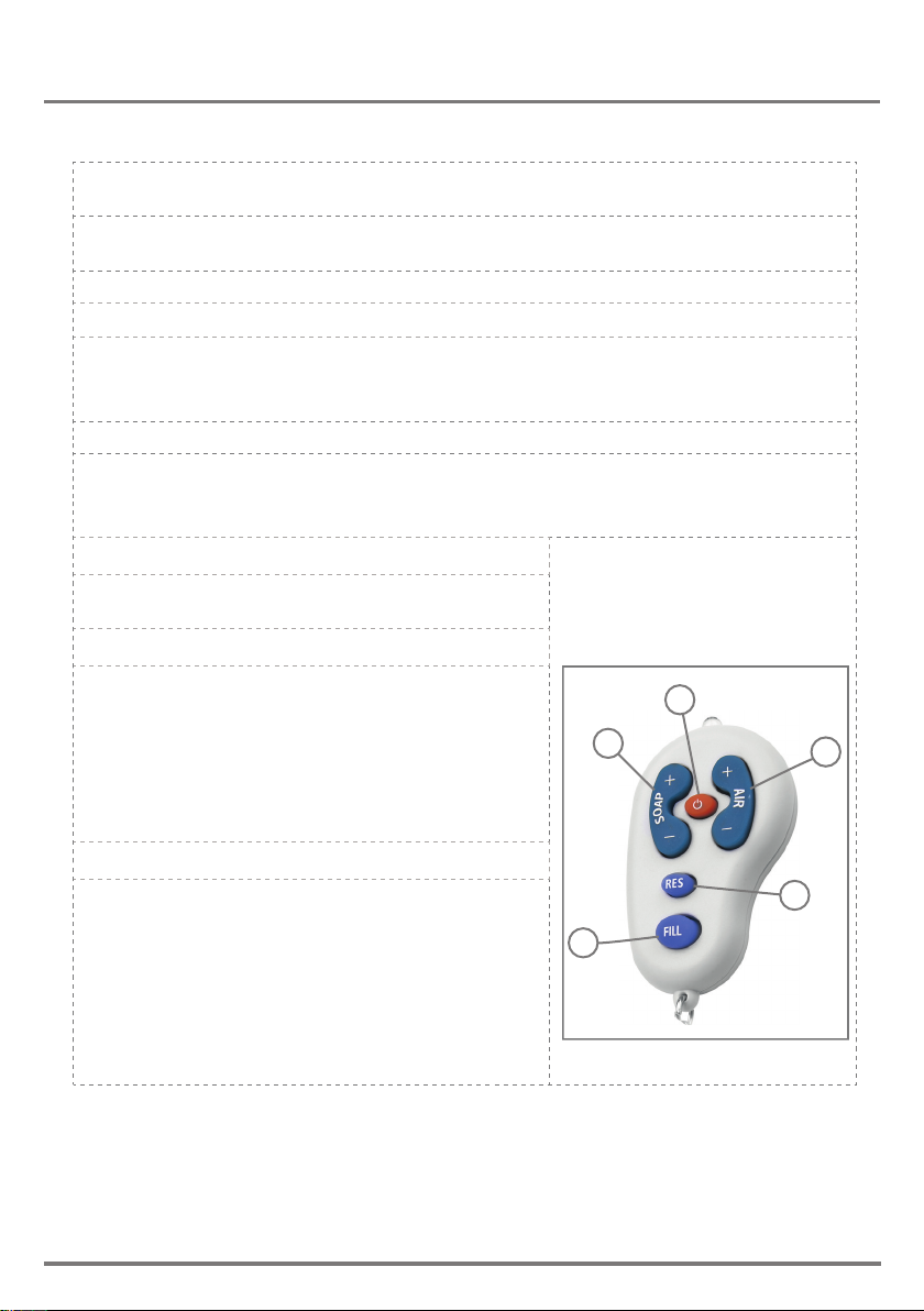
REMOTE CONTROL FUNCTIONS
If available, the foam dispenser remote control can adjust the dispenser’s settings. To
use the remote control hold it in front of the sensor at a distance of 10-15cm (4-6”).
Attention: The remote control will not operate out of the recommended range (too close
or too far).
The remote control can be used to adjust the following functions :
1-SOAP QUANTITY
Press the + sign on the SOAP button to increase the soap quantity by increasing the
dispensing time. Press the - button to decrease it.
Indication: continuous blinking blue light in the sensor eye.
2-AIR QUANTITY
To improve soap consistency (“foamability) change the amount air to be mixed. Press
the + sign on the AIR button to increase the air quantity and the - to
decrease it.
Indication: 2 blinks of the blue light in the sensor eye.
3-RESET
This function resets the sensor back to its factory
settings.
4-TEMPORARY OFF FUNCTION
This function temporary disables the dispenser. Use
this function to preform maintenance in front of the
sensor without activating the system (for example:
cleaning). The soap dispenser will shut o for one
minute after this button is pressed once.
To return to normal operation before the minute is
over, press the On/O button again
5-FILL THE SOAP TANK
Once the soap tank has been lled \ relled, press
the FILL button. The pump will run for one minute,
priming the piping with soap.
Once soap begins dispensing from the spout,
priming is complete. press the FILL button again to
stop the priming before the minute is over.
Indication: continuous solid blue light in the sensor
eye.
4
1
5
3
2
10