SureKap SK6000-BF6 User manual

INSTRUCTION MANUAL
MODEL SK6000-BF6 CAPPER
SUREKAP, INC.
579 BARROW PARK DR.
WINDER, GA 30680
770-867-5793
FAX: 770-867-5799

TABLE OF CONTENTS FOR SUREKAP SK6000-BF6
CAPPER INSTRUCTION MANUAL
Pages 1 –2 Instructions for Uncrating Your Capper
Pages 3 -5 Capper Preparation
Page 5 Set-Up & Changeover
Page 6 Blank Application Set-Up Data Sheet
Pages 7 –8 Floating Shoe Height
Page 8 Suggested Contact Patches (for most caps)
Pages 9 –10 Floating Shoe
Page 10 Chute Height
Page 11 Gripper Belt Height
Page 12 Gripper Belts In/Out
Page 13 Spindle Disc In/Out
Pages 13 - 14 Clutched Disc In/Out
Page 14 Chute In/Out
Page 15 Fingers In/Out
Pages 15 - 16 Floating Shoe In/Out
Page 16 Spindle Height
Pages 16 - 17 Spring Set Collar Height
Page 17 Cap Guides
Page 17 Container Separation
Page 17 Spindle Speed Dial Setting
Page 17 Gripper Belt Speed Dial Setting
Pages 18 –21 Instructions for BF6 Cap Feeder
Page 22 Pneumatic Parts Reject Circuit for BF6
Pages 23 –25 Clutch Option
Page 26 Silicone Belt Disclaimer
Page 26 Tightening Discs & Gripper Belts
Pages 27 –36 “A” through “E” Assembly Schematics
Page 37 –41 Chute & Chute Bracket Assembly Schematics
Page 42 Upper C-Chute Assembly Schematic
Page 43 Floating Shoe Assembly Schematic
Page 44 BF6 Cap Belt Conveyor Schematic
Pages 45 –47 SK04/06 Elevator Assembly Schematics
Page 48 Maintenance Schedule Outline
Pages 49 –53 Maintenance Guide
Pages 55 –55 Maintenance Schedule Checklist
Page 56 Dart DC Motor Control Schematic
Page 57 Fiber Optic Amplifier Instructions
Page 58 Electrical Schematic
Pages 59 –63 Gearbox Information
Page 64 Finalized Application Set-Up Data Sheet
Page 65 Hopper Low Level Assist (OPTIONAL; If Equipped)
Additional Pages Optional Equipment

Carla / My Documents 1Rev. Date: 24 August 2018
“SK6000-BF6 Capper Manual-word document (master)”
In the event of damage, please write down a complete description of the damage on the freight
bill and notify the claims department of the delivering carrier. They will inspect and handle your
claim.
The instructions herein are vital for the proper installation, operation and maintenance of this
equipment. Please see that these instructions are read carefully by the persons who will operate
and maintain the SUREKAP equipment.
UNCRATING CAPPER
1. Position the crate on three pieces of 4x4 lumber or equivalent (one under and parallel
with each skid runner). This will raise the crate approximately 3½" to allow access to the
four 1" bolts under the skid. Do not remove the bolts at this time.
2. Remove the wafer board skin from the top and all four sides of the crate. Use a pry bar
or claw hammer to remove the nails. CAUTION: Wear proper eye protection and gloves
when removing the wafer board and framed walls.
3. Remove the 2x4 framed walls from the skid. Use a pry bar or claw hammer to pry off the
framed walls.
4. Remove the box that contains the manual, leveling pads, and any accessories, if
applicable.
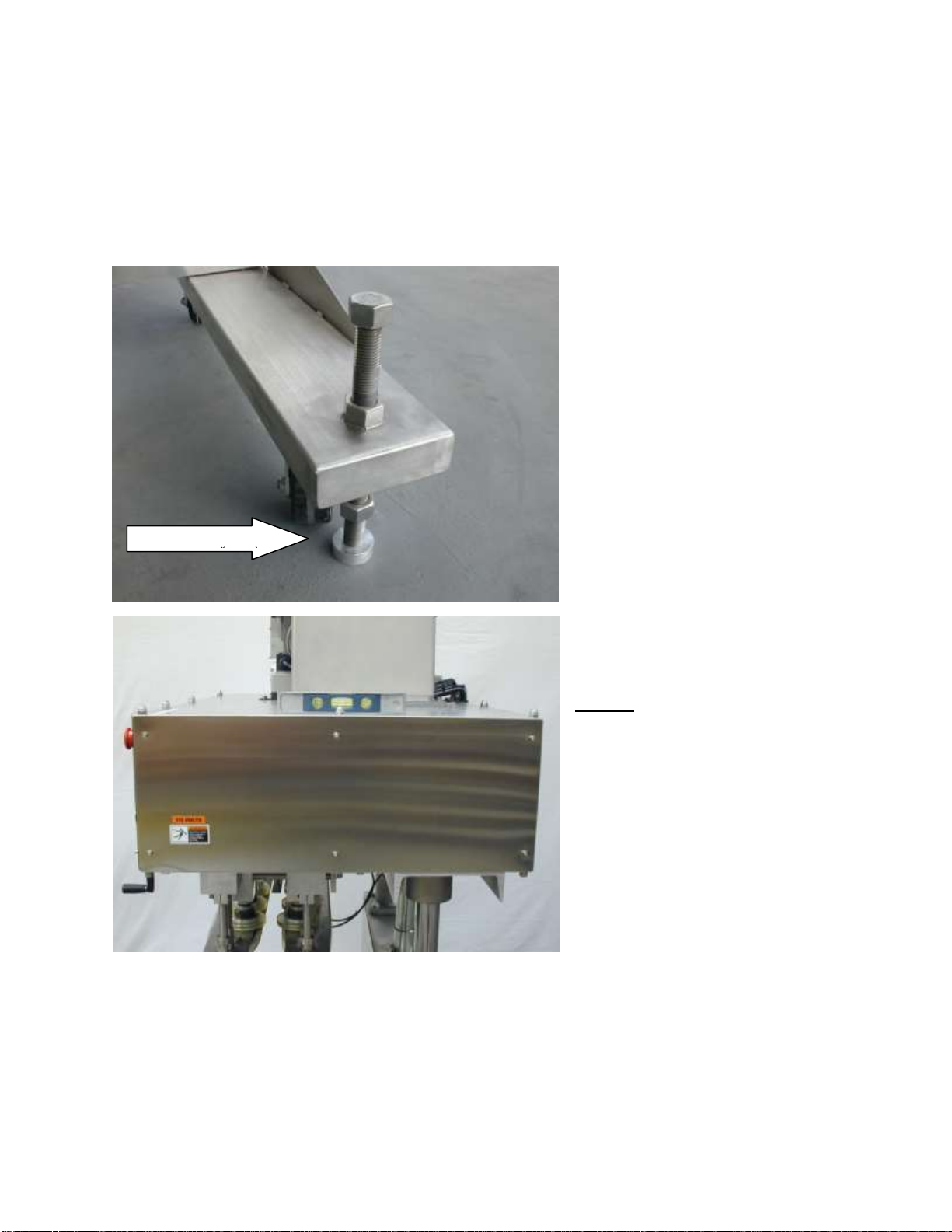
5. The machine is secured to the skid with four 1" bolts threaded from the bottom.. Use a
1½" wrench to loosen the retaining hex nuts on the top of the skid and then loosen the
four 1" bolts that are under the skid. Do not remove the 1" bolts at this time, just have
them loose.
Figure 0.1B
Figure 0.1 A
Welded Hex Mounting Nut
1” Mounting Bolt
1 ½” Retaining Hex Nut & Washers

Carla / My Documents 2Rev. Date: 24 August 2018
“SK6000-BF6 Capper Manual-word document (master)”
Figure 0.1
1. Remove the four 1" bolts and hex nuts from the machine legs. Note: the bolts will still be
sticking up thru the skid at this time. Important: Save these bolts and the hex nuts, they
are used as the machine leveling bolts. The four large washers are used for crating
purposes only. CAUTION: Do not allow the machine to roll off of the skid.
2. Using a forklift with a minimum capacity of 3,000 lbs, slowly and carefully pick the
machine up off of the skid and place it on the floor.
For cappers and tighteners, it is recommended to approach the machine from the side and
position the forks below the legs of the frame and in between the casters. For cappers,
pick up from the side that does not have the cap feeding chute. CAUTION: Do not
damage the cap feeding chute or allow the machine roll off of the skid.
For tables with a feeder bowl and/or hopper, position the forks under the top of the table
and lift the table off of the skid. CAUTION: The feeder bowl is much heavier than the
hopper. Position the forks so that the table is properly balanced. CAUTION: Do not let
the machine roll off of the skid.
3. Install the four 1" leveling bolts down into the top of each leg. Install the hex nut on each
1" bolt from the underside of the leg. The aluminum leveling pads should be installed
below the 1" bolts after the machine is positioned over the conveyor. Refer to the
manual for detailed instructions on initial setup of machine.

Carla / My Documents 3Rev. Date: 24 August 2018
“SK6000-BF6 Capper Manual-word document (master)”
CAPPER PREPARATION
The purpose of this section is to familiarize you with the capper and to prepare it for set-up and
operation.
Step 1: Familiarize yourself with all on/off switches, speed adjustments, and the red emergency
stop button.
Step 2: Make sure all capper and related equipment switches are off. Check the color coded
plugs to the following: Bowl, Hopper, Air Jet Manifold Solenoid, Bowl/Hopper Limit Switch
(Red = Bowl; Blue = Hopper; Yellow = Limit Switch; Green = Air Jet Manifold). If you have a
BF6 Model, they will be Red = Cap Belt; Blue = Elevator.
Step 3: Plug in the power source (115/60 unless ordered differently). TWIST the
EMERGENCY STOP on/off button. Press the START button. Energize the gripper belts and
the spindles by turning on their individual control buttons. After viewing their operation, test the
EMERGENCY STOP by pushing the red button.
Step 4: Put some caps into the hopper, power up the machine and turn on the Bowl and Hopper
through their individual controls and view their operations. If you have a BF6 Model, turn on
the Cap Belt and Elevator. Hook up the air to the air jet manifold and familiarize yourself with
its function in relation to the bowl. If you have a BF6 Model, hook up the air and test the cap
reject system. Once you have become familiar with these functions, push all buttons off and
unplug the power cord and compressed air.
Step 5: Level your conveyor, front to back and side to side, in the area in which the capper is to
be installed. This step is important to achieve container stability and proper capper operation.
Step 6: Raise the capper head high enough so the gripper belts will clear your conveyor by
approximately 6 inches. The head of the machine can be raised or lowered using the jack built
onto the machine. Depending on machine orientation, the jack will either have its crank handle
1” Leveling Bolt
Hex Nut
Carla / My Documents 4Rev. Date: 24 August 2018
“SK6000-BF6 Capper Manual-word document (master)”
attached in the rear or will have a loop shaft attached in the front, which will require use of the
jack handle held to the side of the machine by a magnetic strip.
Step 7: Roll your capper over your leveled conveyor. The center line of your conveyor should
line up with the center of the two gripper belts, the chute, floating shoe, fixed hold-down, etc.
Step 8: For proper operation, the capper must be level front to rear and side to side. To level the
machine, there are (4) round
aluminum pads that are shipped
with the machine (there will be (8)
pads for a SK6000-SP model).
These pads are usually in the box
with your manual.
Place (1) pad under each leveling
bolt.
Place your level on the large top
plate of the capper. If your capper
is not level, screw one or more
levelers down to lift the necessary
corner or entire side. When
turning levelers, use a 1-1/2 inch
socket or open-end wrench and
make gradual adjustments. When
leveling, the casters should be off
the floor, but keep the capper as
low to the floor as possible.
NOTE: If your capper is far
enough out of level, front to rear,
when screwing the levelers you
might end up with the capper off
center of your conveyor.
Compensate for this by first rolling
the capper one or two inches
forward or backwards before
leveling. After the capper is level
and centered, raise the container
entry end of the capper by turning
the (2) leveler bolts (on the entry
side) one complete turn. This will
create a downward pressure on the container against the conveyor. If you have an SP Model,
move the Bowl and Hopper table into position so that the Bowl discharge and cap chute are in
alignment with each other. This will require the SP table to be raised or lowered accordingly to
the height of the capper and chute. There should be a gap (approximately 1/16" to 1/8") between
the bowl discharge and cap chute that will not allow the two to rub each other during operation,
but as close as possible. Use the leveling bolts and pads just as described in the leveling of the
Leveling Pad
©~PjQ»‰õtŽ ÿZà̦

Carla / My Documents 5Rev. Date: 24 August 2018
“SK6000-BF6 Capper Manual-word document (master)”
capper. CAUTION: Be careful not to crank the chute into the feeder discharge or the
feeder discharge into the chute.
SET-UP AND CHANGEOVER
Using the Application and Set-Up Data Sheet:
As parts of SUREKAP’s final testing and documentation procedure, your capper has been
performance tested with container and cap combinations provided to us. From each container
and cap combination tested and approved, a series of measurements are documented onto the
SUREKAP Application and Set-Up Data Sheet to allow you, the customer, to duplicate the set-
up with an established baseline for set-ups and changeovers to other caps and containers. With a
proper understanding of each measurement’s reference points, it is possible to duplicate the
factory recommended specifications that yield the highest operating performance. The following
information briefly defines the theories behind each adjustment and also defines from where
each measurement is scaled.
To begin using the SUREKAP Application and Set-Up Data Sheet, it is assumed that the capper
has been correctly and exactly placed over a container transport conveyor. The correct
relationship between the capper and conveyor is crucial for trouble-free operation. Do not
assume the capper will operate with any degree of success if the initial capper set-up procedures
have been neglected.
To begin, you will need the following:
1. The capper system correctly placed over the container transport conveyor.
2. A six and a twelve inch flexible steel rule, scaled in one thirty seconds of an inch. In
some cases, an eighteen or twenty-four inch scale is required. A metal scale provides a
much more accurate measurement than a ruler or a tape measure.
3. A set of hex keys (sometimes referred to as Allen or “L” wrenches). The set should
range from 1/8 to 5/16 of an inch.
4. The SUREKAP Application and Set-Up Data Sheet. Take a moment to get familiar with
the format of the sheet. The top of the Set-Up Data Sheet contains information such as:
customer, machine type and serial number of the tested machine. At the far left of the
page are the reference points (A through R), which run vertically (up and down). Notice
the first and second horizontal (left to right) row list the cap and container combinations
tested. Locate the vertical column that has the cap and container combination you wish
to adjust the capper to run. Following the column downward, adjust the capper to the
measurement specified in each window. It is recommended to follow the order as they
are listed; this is most important for the first three windows, as they are related to each
other. Once the first three measurements have been set, the order of the rest can be
varied to suit, in some cases they will have to be in an order to make room for the scale,
the tool or the hand.

Carla / My Documents 6Rev. Date: 24 August 2018
“SK6000-BF6 Capper Manual-word document (master)”
APPLICATION SET-UP DATA SHEET
Customer: ________________________________________
Date: ______________________________
Machine Type / Serial No: ___________________________
Prepared By: ________________________
Cap Size / Type: __________________________________
Bottle / Size / Type: __________________
A
Floating shoe block height
S
Conveyor speed (FPM)
B
Front floating shoe height (Locked)
□
T
Fixed hold down
C
Chute height
Y
Finger number
D
Gripper belt height (drop)
V
Floating Shoe number
E
Gripper belts in - out
W
Cap Alignment Cylinder
F
Spindle discs in - out *
X
Fiber Optic Trigger Level
G
Clutched discs in - out *
Y
Fiber Optic ON Delay
H
Chute in - out
Z
Fiber Optic OFF Delay
I
Fingers in - out
AA
2nd Floating Shoe height
J
Floating shoe in - out
BB
Flipper number
K
Spindle height - 1st set
QUICK CHANGE PACKAGE ONLY
L
Spring set collar height
Gripper belts in - out
M
Cap guides
Spindle discs in - out *
N
Bottle separation
Clutched discs in - out *
O
Spindle speed dial setting
Chute in - out
P
Gripper belt speed dial setting **
Capper Height Gauge
Q
Cap Belt / Bowl speed dial setting
Chute Bracket Scale
R
Elevator / Hopper speed dial setting
* The purpose of these measurements is to give you a starting point when setting up the machine. As your discs wear, these
measurements will change.
In most cases, the first set of discs should touch the cap just enough to start it onto the bottle. Any clutched sets should hit the cap just
hard enough to "kick out" the clutches.
** This is the speed dial setting that was used during in plant testing. The gripper belt speed should match your conveyor speed.
*** Please note that all measurements given are in inches (unless otherwise specified).

Carla / My Documents 7Rev. Date: 24 August 2018
“SK6000-BF6 Capper Manual-word document (master)”
CAPPER HEIGHT
Adjusting the height of the capper is important in order to achieve proper cap placement and cap
torque. The first dimension on the Application Set-Up Data Sheet is:
A. FLOATING SHOE BLOCK HEIGHT
Measure from the bottom of the aluminum block to the top of the conveyor belt. The
Floating Shoe Block Height is simply a reference point in which to define the capper’s height
over the bottle transport conveyor. The distance between the floating shoe block and the
conveyor is easily measured and in actuality is just a reference point in determining where
the spindle discs are in relationship to a cap installed on a bottle that is placed on the
conveyor. The floating shoe block height could technically be called the spindle disc height
because this is what you are actually setting. The spindle discs move up and down with the
entire capping head and are not adjustable in height from the conveyor except by moving the
entire capper head as a unit. The first set of spindle discs are the exception which is defined
later in the chapter. The floating shoe, the chute and the gripper belts are able to move
independently up and down, away or closer, to the capper head so it is imperative to set the
floating shoe block height first. In determining the proper relationship of the spindle discs to
a bottle cap (or floating shoe block height) one must examine the type of cap processed.
Different caps behave in different ways. For example, is it a flat cap or a deep skirted cap?
Is there a butterfly hinge protruding from the cap’s sidewall? These are the type of points
that have to be taken into consideration when determining the optimum location where the
spindle disc may properly contact a particular cap.
Before comparing the spindle disc contact patch to the bottle cap, it is recommended to fill
the bottle with product because with some types of containers the height of the cap could
slightly be different.
The cap should be seated and slightly torqued to the bottle. The last set of discs or 3rd set on
a SK6000, 4th set on an SK8000, should be referenced from when adjusting the floating shoe
block height.
1. To adjust the floating shoe block height.
2. Remove the crank handle from its storage magnet located on the discharge side of the
capper's C frame. Engage the loop end of the crank handle to the loop end of the jack
shaft.
3. Rotate the crank handle counterclockwise to increase the floating shoe block height
(or raise the capper). Rotating the jack handle clockwise will decrease the floating
shoe block height (or lower the capper).
GENERAL GUIDE LINES
1. Set the disc contact in relationship to the cap as high up on a cap as possible.
Typically, continuous threaded caps are stronger and more rigid towards the top than
the lower skirt side of the cap. Setting the disc to cap contact patch towards the lower
skirt end will tend to oval the cap, increasing the friction between the cap and bottle
threads resulting in lost cap torque.
2. Use as much of the spindle disc as practical. More contact between cap and disc
equals more friction which means more torque.
3. Avoid contacting areas on caps like “thumbnail catches”, “turret spouts”, “and sport
cap hoods”.

Carla / My Documents 8Rev. Date: 24 August 2018
“SK6000-BF6 Capper Manual-word document (master)”
4. Setting the disc height is only part of the picture in getting properly torqued cap on a
bottle. See also sections entitled “Spindle Disc Clutches”, “Spindle Disc Height, 1st
set”, “Spindle Disc In/Out”.
SUGGESTED CONTACT PATCHES FOR MOST CAPS
Typical 400 Style Flat Caps, Typical CRC In most cases, a flat cap is about the
same thickness as a spindle disc so
setting the disc evenly with the cap is the
best way. Some caps have a slight ring
at the cap’s skirt that will scuff easily. In
this case, it may be better to set the disc’s
bottom corner slightly above the cap’s
skirt.
Typical 410 Style Caps The 410 cap has a longer skirt or deeper
sidewall than a 400 series cap. In most
cases, a 410 style cap will be thicker than
a tightening disc thickness. It is
recommended to try and keep the disc’s
contact patch towards the top of this cap.
The cap is stronger towards its top than it
is towards its skirt.

Carla / My Documents 9Rev. Date: 24 August 2018
“SK6000-BF6 Capper Manual-word document (master)”
CONVEYOR
A
B
C
B. FLOATING SHOE Measure from the bottom of the front shoe to
the top of the conveyor belt. The purpose of
the floating shoe is to keep a light but constant
pressure on the cap until the first set of
spindles can start the cap and container
threads. The floating shoe is adjustable in
height by adjusting the set collar on the shaft
of the front shoe. It is also spring loaded and
spring tension can be increased or decreased
by raising or lowering the set collar
underneath the spring. You can also move the
floating shoe block (the block that holds the
floating shoe shafts) by loosening the socket
head cap screw at the bottom of the mount shaft.
STEP 1: Place a cap on top of the container
threads. Do not screw the cap down onto the
container. Place the container and cap on the
conveyor underneath the rear floating shoe,
turn the cap backwards on its threads until it
snaps down. Your cap will now be at its
lowest point. Adjust the set collar on the front
shoe shaft until there is about 1/16" to 1/8"
gap between the front and rear horseshoe
blocks on the floating shoe shaft. This will
give a light amount of pressure on the cap.
Carla / My Documents 10 Rev. Date: 24 August 2018
“SK6000-BF6 Capper Manual-word document (master)”
Setting the shoe too high will allow the cap to fall off before it gets to the spindles or will
allow the first set of spindles to spin the cap off of the container. Setting the shoe too high
can also result in a cross-threaded cap. Setting the shoe too low will allow the shoe to knock
the cap off of the container upon impact.
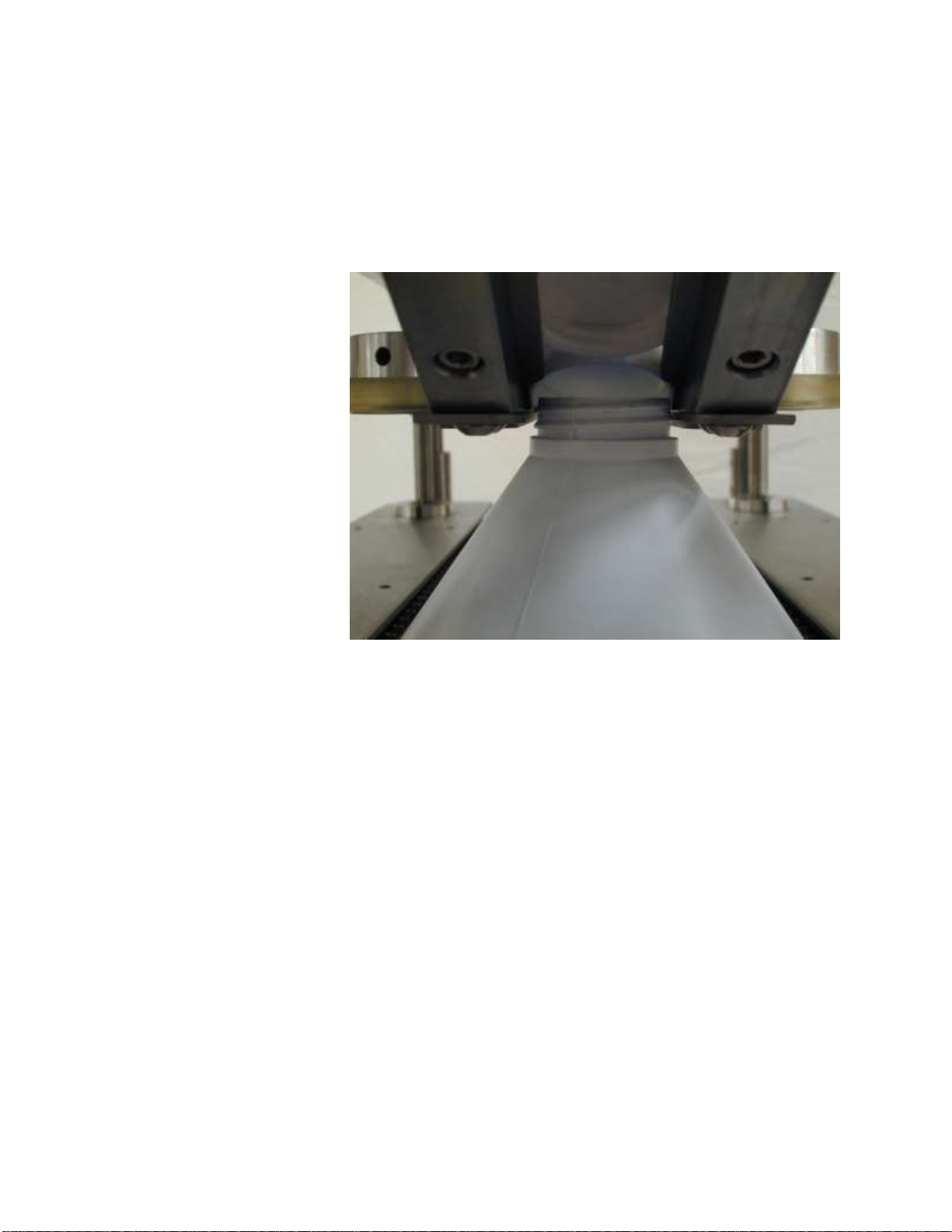
C. CHUTE HEIGHT
Measure from the bottom
edge of the chute exit
block (or the top of the
cap guide if installed) to
the top of the conveyor
belt. In order for the
container to consistently
pull the cap out of the
chute (straight chute or
C-chute type), the chute
must be adjusted to the
proper height. Too high
or too low, or off-center,
will result in missed
and/or cross threaded
caps. To adjust the
height of the chute, first
open the gripper belts so
that a container can be passed underneath the chute by hand on top of the conveyor. There
are (2) bolts, (1) on each side of the slotted bracket that supports the chute. Loosen these
bolts. You can now raise or lower the chute by turning the knob on the chute bracket. The
neck, or threaded section of the container, should be able to pass through the notched section
of the chute rails at the bottom of the chute. Adjust the chute so that there is approximately
1/16" of clearance between the container and the chute.
Carla / My Documents 11 Rev. Date: 24 August 2018
“SK6000-BF6 Capper Manual-word document (master)”
D D
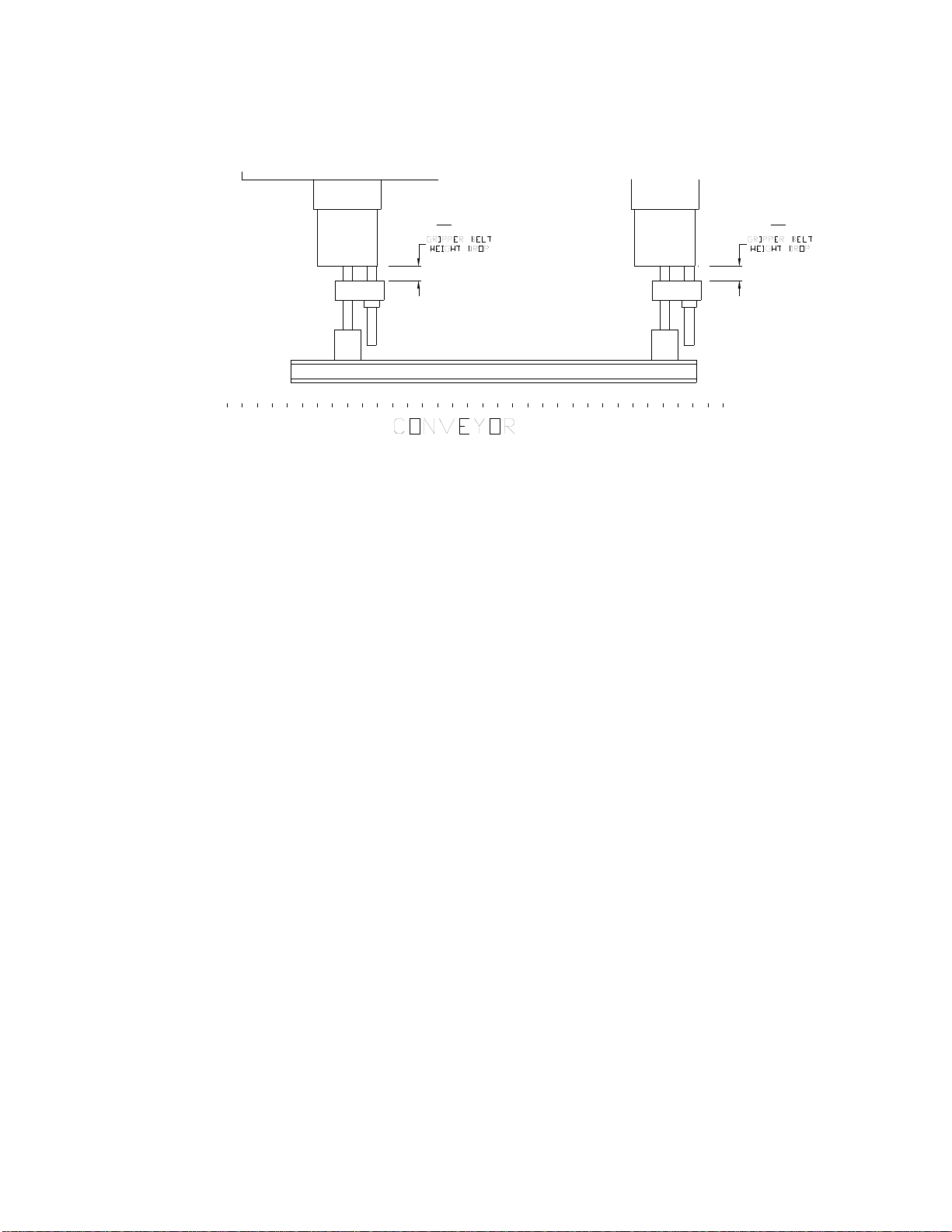
D. GRIPPER BELT HEIGHT (Drop)
Measure from the top of the aluminum knuckle (cross block) to the bottom of the aluminum
slide block. The purpose of the gripper belts is to grab and stabilize the containers securely
while traveling through the capper. The belts should grab the container at the highest
position possible below the container threads for optimum container stability. If you are not
able to grab the container up high close to the threads (due to the shape/contour of the
container), than select the section of the container that is the most rigid, provides stability and
is as high as possible. When the gripper belts are near the center of the container, the
container may become unstable because this is close to the pivot point of the container.
Moving the gripper belts up or down is necessary, at times, due the various shapes and sizes
of containers.
Step 1: To raise or lower your belts, loosen the set collar and knuckle socket head cap
screws on both ends of one assembly. Slide the assembly up or down to the desired height.
Retighten the socket head cap screws on the knuckles and retighten the shaft set collar.
Step 2: Do the same for the other assembly. IMPORTANT: DO NOT loosen the tamper
proof torx fasteners. Also DO NOT allow the top end of the gripper belt drive SHAFT
to slide out of the tolomatic slide rite. There should be a snap ring on the top end of the
shaft to prevent this. Before lowering, inspect to make sure the snap rings are in place.
The front and rear gripper belt assemblies should be equal in distance from the measuring
points. Do not have one assembly lower than the other. The front and rear gripper belt
assemblies must be set to the same height.

Carla / My Documents 12 Rev. Date: 24 August 2018
“SK6000-BF6 Capper Manual-word document (master)”
E
E. GRIPPER BELTS IN/OUT
Measure the distance between the top plates of the gripper belt assemblies on the infeed end
only. The gripper belts move in and out on center (to accommodate different container
diameters) with a crank handle on the front (or rear) of the machine. There is also a lock
knob that keeps the handle from being moved once it is set. Do not turn the crank handle if it
is locked. This can cause the flexible shaft coupling to rupture.
Step 1: Place your container on the conveyor.
Step 2: Adjust the (3) sets of spindles out enough so that your container can pass through
unrestricted.
Step 3: Open your gripper belt assemblies by turning the crank hndle clockwise. Slide your
container into the center of the assemblies. Now tighten the assemblies until they have a
firm, but not crushing, grip on the container.
Step 4: Turn the belts and conveyor on and run the container through a couple of times to
verify proper grip. You should not be collapsing the side of the container and the container
should not be slipping in the belts. Check the gripper belt tightness later on when you have
the spindles set at the proper torque levels, to check for container slippage. IMPORTANT:
The conveyor must run at a speed equal to the gripper belt speed. Check to make sure
the container stays in the same position on the conveyor while the gripper belts are in
contact with the container.
Carla / My Documents 13 Rev. Date: 24 August 2018
“SK6000-BF6 Capper Manual-word document (master)”
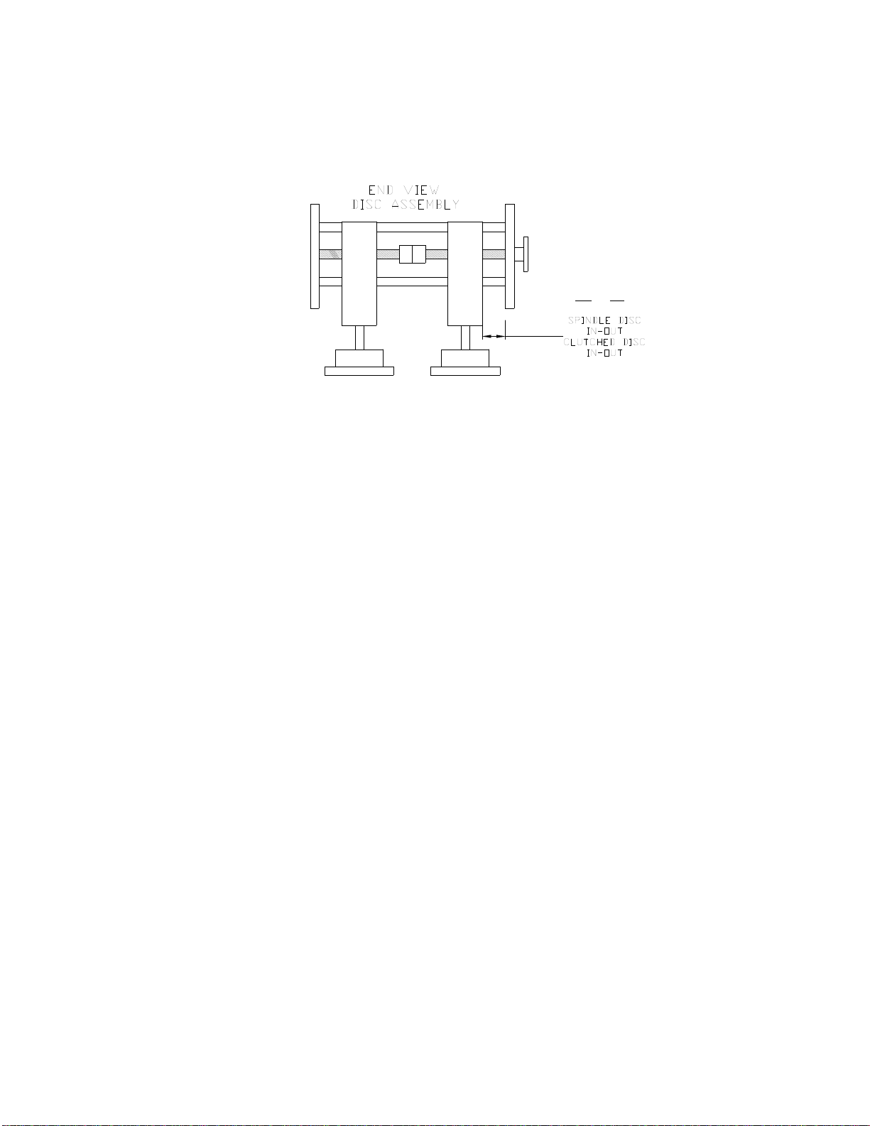
F & G
F. SPINDLE DISC IN/OUT (1st Set)
Measure the distance between the inside of the cage face plate and the cage block on the
operator’s side. The purpose of the 1st spindle set is to start the cap onto the container
threads. The spindle moves in and out, on center, by turning the appropriate knob. The
tightening discs only need to lightly touch the sides of the cap. If there is too much pressure,
you may not be able to start the cap on the threads. The spindle speed will need to be
adjusted so that the tightening disc spins the cap down completely until the cap is fully
seated.
Step 1: Adjust the 1st set of spindles (by turning the spindle knob) until the 1st set of
tightening discs lightly touch the sides of the cap.
Step 2: Turn on the conveyor and gripper belts. Turn on the spindles.
Step 3: Place your container on the conveyor and run it through the capper. The 1st set of
spindles should screw the cap down on the container (not tighten the cap). Adjust
accordingly, if needed. Secure the spindle knob with the lock knob.
G. CLUTCHED DISC IN/OUT
Measure the distance between the inside of the cage face plate and the cage block on the
operator’s side. Clutches have been installed on the 2nd and 3rd set of spindles. When
adjusted properly, the clutches will stop the spindle and tightening disc from spinning after
applying the desired amount of torque to the cap. Increased cap torque can be achieved by
adjusting the mechanical clutches (with the machine turned off) by turning the knurled ring
(with your fingers) clockwise to increase torque; counter-clockwise to decrease torque. A
small adjustment makes a big difference in performance. When turning the knurled ring, you
can feel it “click”. Count the “clicks” so you can set each side equally. CAUTION: Do not
attempt to adjust the clutch with the machine and/or spindles on.
Carla / My Documents 14 Rev. Date: 24 August 2018
“SK6000-BF6 Capper Manual-word document (master)”
Step 1: Place the container on the conveyor and run it through the capper.
Step 2: Adjust the clutched spindles until the tightening disc touch the sides of the cap. The
2nd set should tighten the cap. The 3rd set should apply the final amount of torque to assure
the cap is tight. The 2nd set should appear to do most of the work.
Step 3: Adjust accordingly, if needed. Secure spindle knob with the lock knob.
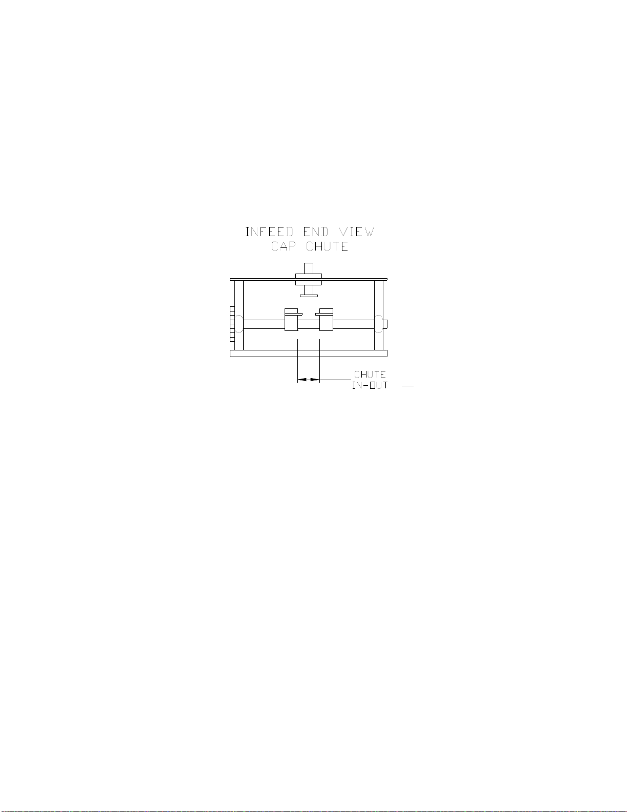
H
H. CHUTE IN/OUT
Measure between the inside edges of the 3/4" x 3/4" stainless steel cross blocks on the entry
end of the chute. SUREKAP manufactures two types of chutes: a straight chute and a “C”
chute. The purpose of both is to feed caps from your bowl to your container. The side rails
that confine the cap move in and out from center for different diameters of caps with a single
turn knob. The top confinement is adjustable up and down for different height caps.
Step 1: Adjust the chute for your cap diameter by turning the knob to open or close the side
rails, allowing the caps to slide from the entering end of the chute to the exit end unrestricted
all the way down to the chute fingers. There should be enough space to keep the caps from
jamming in the chute; approximately 1/32" to 1/16" on each side of the cap normally works
well.
Step 2: The top confinement rail should be adjusted up or down so there is approximately
1/16" clearance from the top of the cap to the rail. A cap should now slide freely from the
bowl discharge to the chute guide fingers. If not, make the necessary adjustments to free the
binding cap.
Carla / My Documents 15 Rev. Date: 24 August 2018
“SK6000-BF6 Capper Manual-word document (master)”
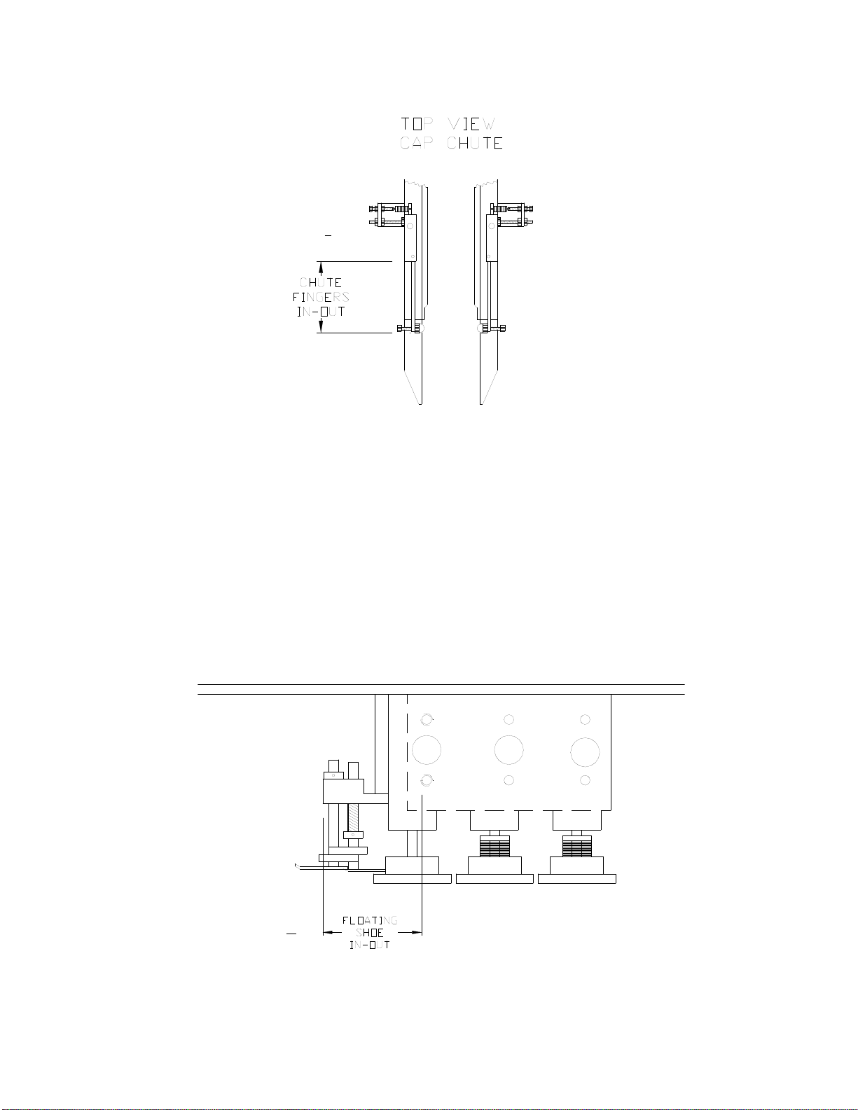
I
I. FINGERS IN/OUT
Distance that the rod fingers extend from the mounting block. Measure from the end of the
chute finger blocks to the end of the chute fingers (1/4" dia. stainless steel rod). The chute
fingers are located on the lower end (discharge) of the chute. The fingers are designed to
hold the caps in the chute. They are spring loaded so that the container can pull the cap out
of the chute when it passes and then springs back into place to continue holding the caps.
The nylon nut on the end of the fingers is sized to work with a wide range of cap diameters
and styles, therefore it is adjustable. At times, certain caps may require that the nylon nut is
not used because it wraps too far around a cap and preventing the cap from being pulled out
correctly (usually causes taller caps to tilt). The chute finger wrap is then changed by
rotating the finger 180º to the modified finger wrap. If non-standard chute finger wrap is
required, it will be indicated on the set-up sheet.
J
J. FLOATING SHOE IN/OUT
Carla / My Documents 16 Rev. Date: 24 August 2018
“SK6000-BF6 Capper Manual-word document (master)”
Measure the distance from the front of the aluminum block to the leading edge of the 1st
horizontal cage shaft (3/4" stainless steel shaft). Different cap heights and diameters require
that the floating shoe be adjusted horizontally over the top of the cap as it exits the chute, so
that is lays down over the container threads correctly. The floating shoe is mounted in a
block that can be moved either closer to the cap and chute flipper, or further away. The
floating shoe height always affects this adjustment.
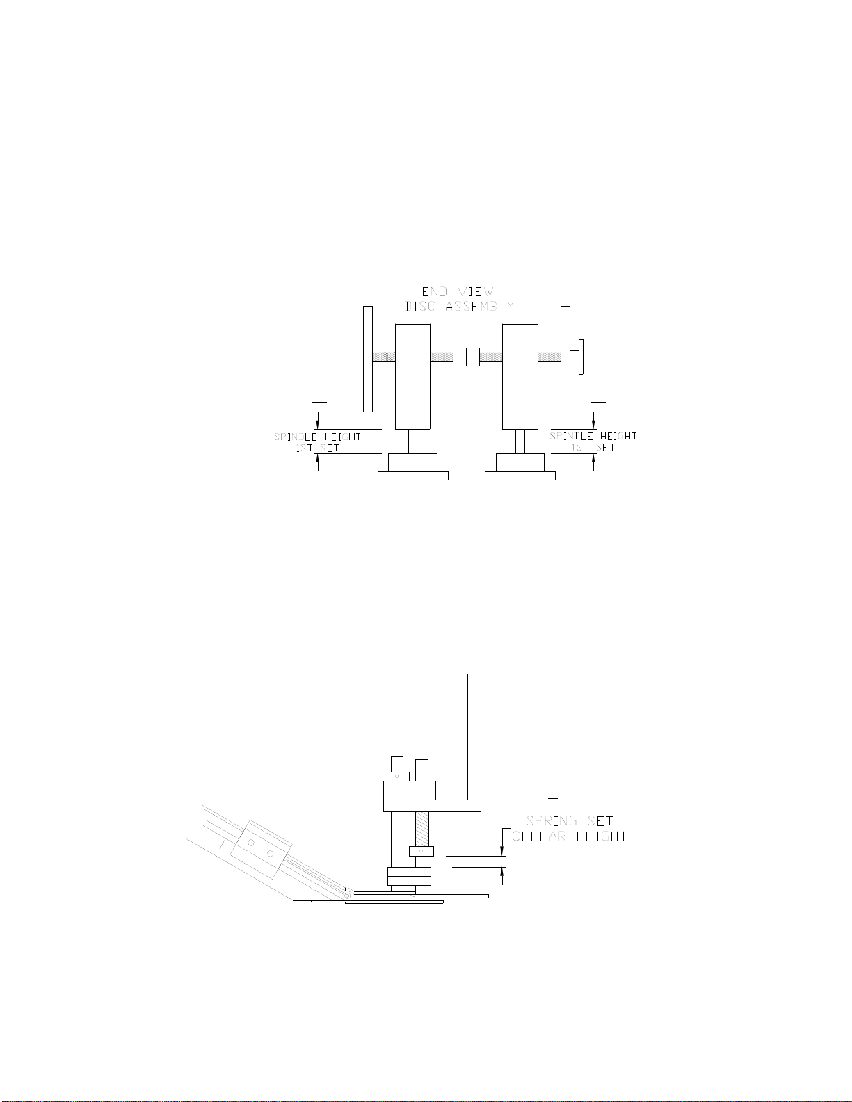
K K
K. SPINDLE HEIGHT
Measure the distance from the top of the disc hub to the bottom of the cage block. 1st Set:
The 1st set of spindle discs are used to spin and start the caps on the container threads.
Because the cap is at its highest position before starting on the threads, the tightening disc
must make contact with the cap properly at this point. Too low and they may squeeze the
bottom of the cap and not allow it to go on. Too high and it may not spin the cap on
completely.
L

Carla / My Documents 17 Rev. Date: 24 August 2018
“SK6000-BF6 Capper Manual-word document (master)”
L. SPRING SET COLLAR HEIGHT
Measure from the top of the tie bar to the bottom of the shaft collar. This set collar is used to
adjust spring pressure for the floating shoes. It is located on the rear floating shoe shaft, just
above the horseshoe guide.
M
M. CAP GUIDES
Cap Guides are attached to the bottom of the chute and are used to guide caps in their
forward motion, so that they will seat properly on the container threads without cross-
threading. They are normally used on Flat caps (400’s), CRC’s or metal caps. If your cap
and container combination has been tested by SUREKAP, we will indicate whether or not
they are used. If you have a style of cap that may require them, please contact SUREKAP
for the correct application. Cap Guide Installation is covered in another section of this
manual.
N. CONTAINER SEPARATION
During testing, it is determined if containers can run touching, or if they require separation in
order to properly pull caps out of the chute, and for proper floating shoe movement. The
minimum distance between containers is indicated.
P. SPINDLE SPEED DIAL SETTING
Spindle speed can vary with cap diameter and cap torque requirements. Normally, the speed
is set so that the 1st set of discs (non-clutched) spins the cap completely onto the threads of
the container.
Q. GRIPPER BELT SPEED DIAL SETTING
The gripper belts are set to match the speed of the conveyor. Too fast, and containers will
lean or tilt forward and the base of the container will slide forward on the conveyor faster
than it is moving. Too slow, and the container will lean or tilt backward and the base of the
container will slide backward on the conveyor slower than the conveyor is moving.
Carla / My Documents 18 Rev. Date: 24 August 2018
“SK6000-BF6 Capper Manual-word document (master)”
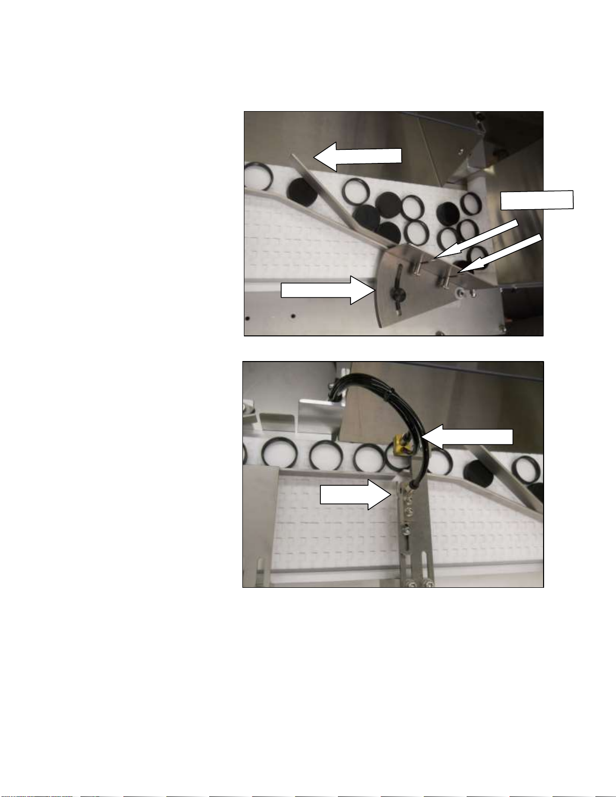
INSTRUCTIONS FOR BF6 CAP FEEDER:
1. Wiper Height: Set height
of the wiper blade (using
the thumbscrews) so that it
wipes off the layer of
double stacked caps into
the return chute.
2. 1st Deflector: Set the
deflector so that the single
layer of caps forms a single
line. The outside edge of
the cap should run as close
to the edge of the conveyor
as possible, without
bumping into the edge of
the return chute with the
belt running.
3. Sensor Tooling: Consists
of the following parts:
Cap Sensor and Cap Reject
Air Jet. Also consists of
the following adjustments:
Sensor Tooling Location,
Cap Sensor Height, Cap
Sensor Centering, Cap
Sensor Advance/Retard
and Cap Reject Air Jet
Positioning.
4. Sensor Tooling Location:
Generally the tooling will
be positioned so that the
sensor will be centered
between the edge of the 1st
deflector and the edge of
the return chute.
5. Cap Sensor Height: Adjust the tooling up or down so that caps will pass underneath the
sensor, without being obstructed. Sensor Height will also affect how sensitive the sensor
becomes. Best results are obtained by setting it close to the cap. The further it is from the
cap decreases the sensitivity. (see also Cap Sensor Regulator PSI)
Air Jet
1st Deflector
Wiper Blade
BladBlade
Thumbscrews
¡
Air Gap
Sen•h•è
Table of contents


