Surelight NE-MI User manual
ARTIST OF LIGHT
LED NEON FLEX RIBBON
NE-MI
USER MANUAL
PLEASE READ THESE INSTRUCTIONS CAREFULLY BEFORE
INSTALLATION. LEAVE A COPY FOR THE END USER/MAINTENANCE
ENGINEER FOR FUTURE REFERENCE.
Version No. : V2.0
Table
Of
Contents
02
USER MANUAL www.surelight.com
Unpacking
Basic Parameters
Cautions
Instructions for Cutting Light
Clasp Front Connector
Clasp End Cap
Snap Front Connector
Snap End Cap
Swivel Front Connector
Swivel End Cap
Diagram of Light Wiring
Mounting Profile Options
Troubleshooting
Limited Warranty
Appendix
03
06
07
08
09
13
16
20
24
27
28
30
40
41
42
1 2
3
5 6
78
Unpacking
03
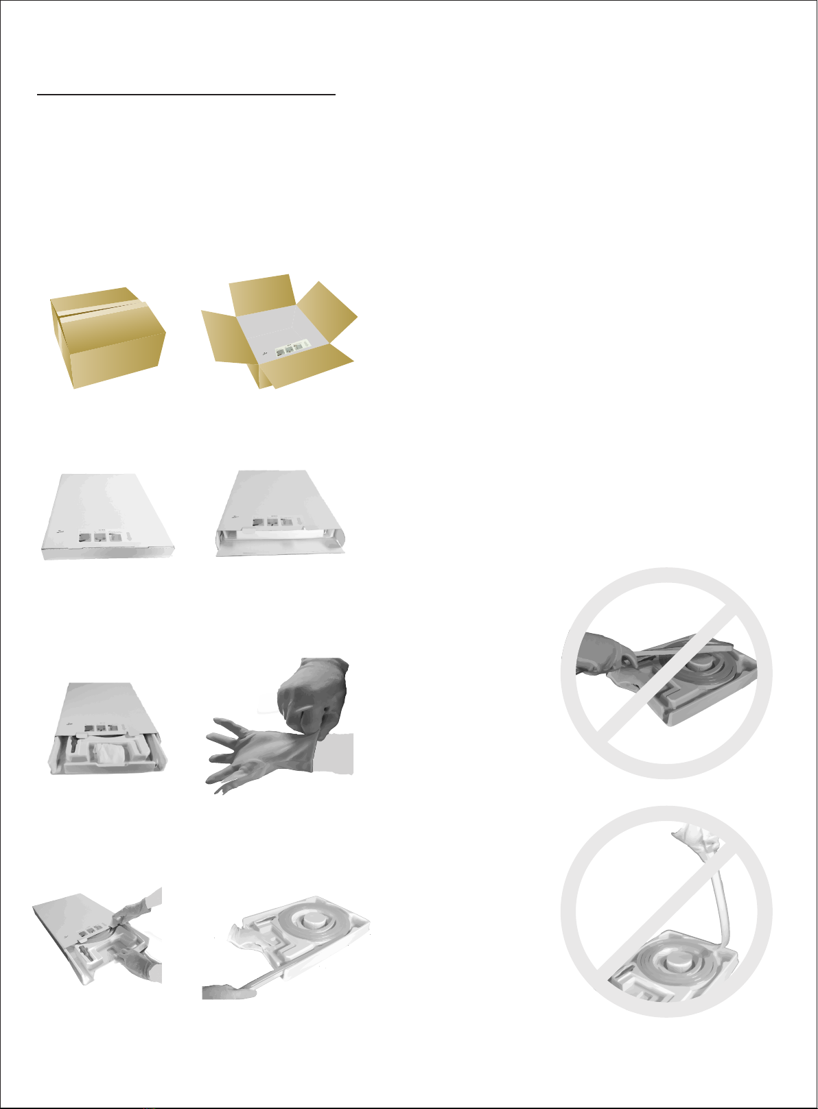
White Box Packaging
USER MANUAL www.surelight.com
Note: Two people are needed to uncoil the light.
Unpacking
04
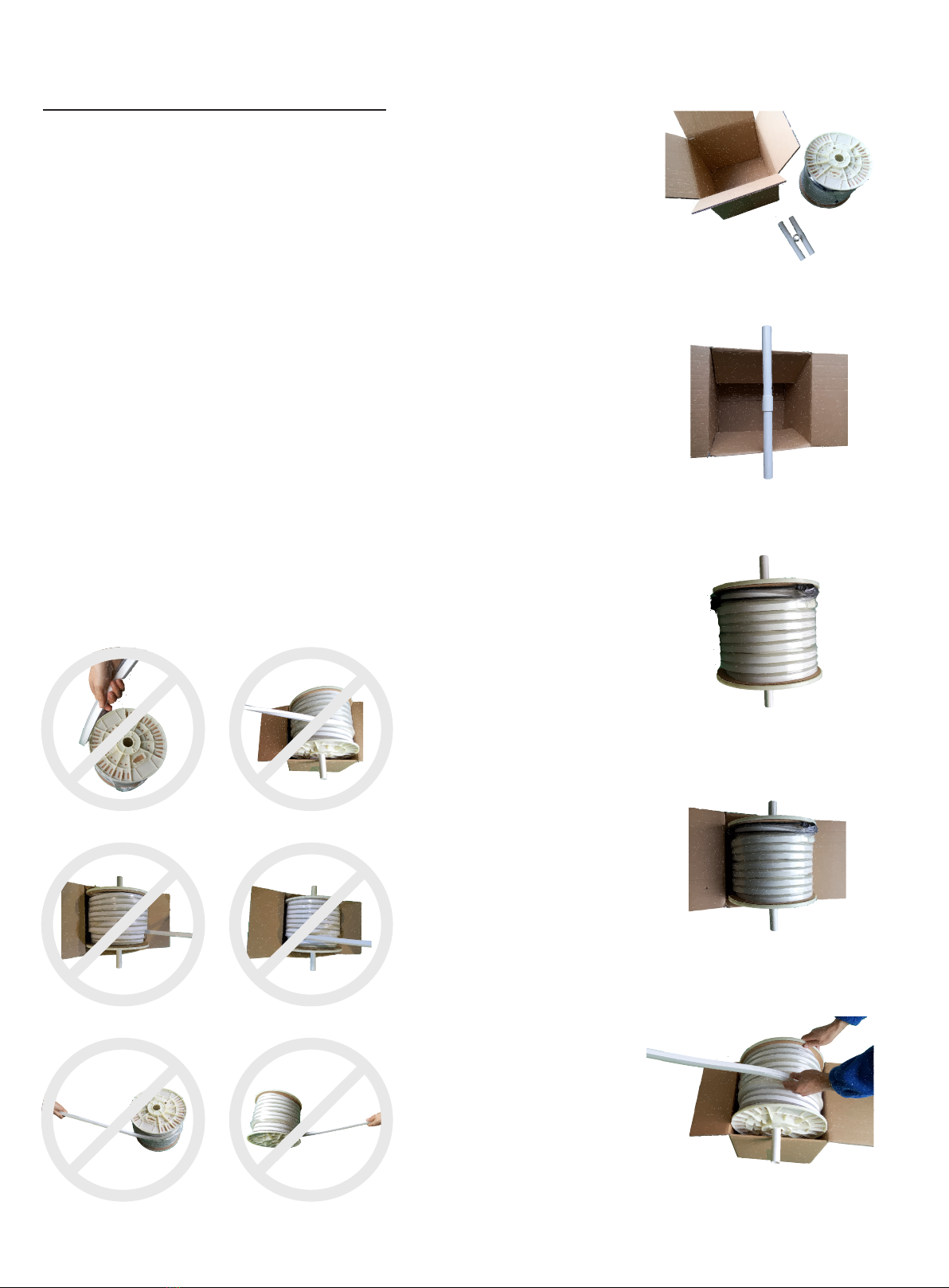
Reel Packaging
1
2
3
4
5
USER MANUAL www.surelight.com

Unpacking
05
Uncoiling Roller
Uncoiling Roller (Optional Device)
USER MANUAL www.surelight.com
Roll up the rest of the light
Protect the light end and fix it
Use recommended cutter to cut
the light vertically
Rotate the roller edge to uncoil the
light with another hand
Put the light on the middle of
uncoiling roller
Basic
Parameters
06
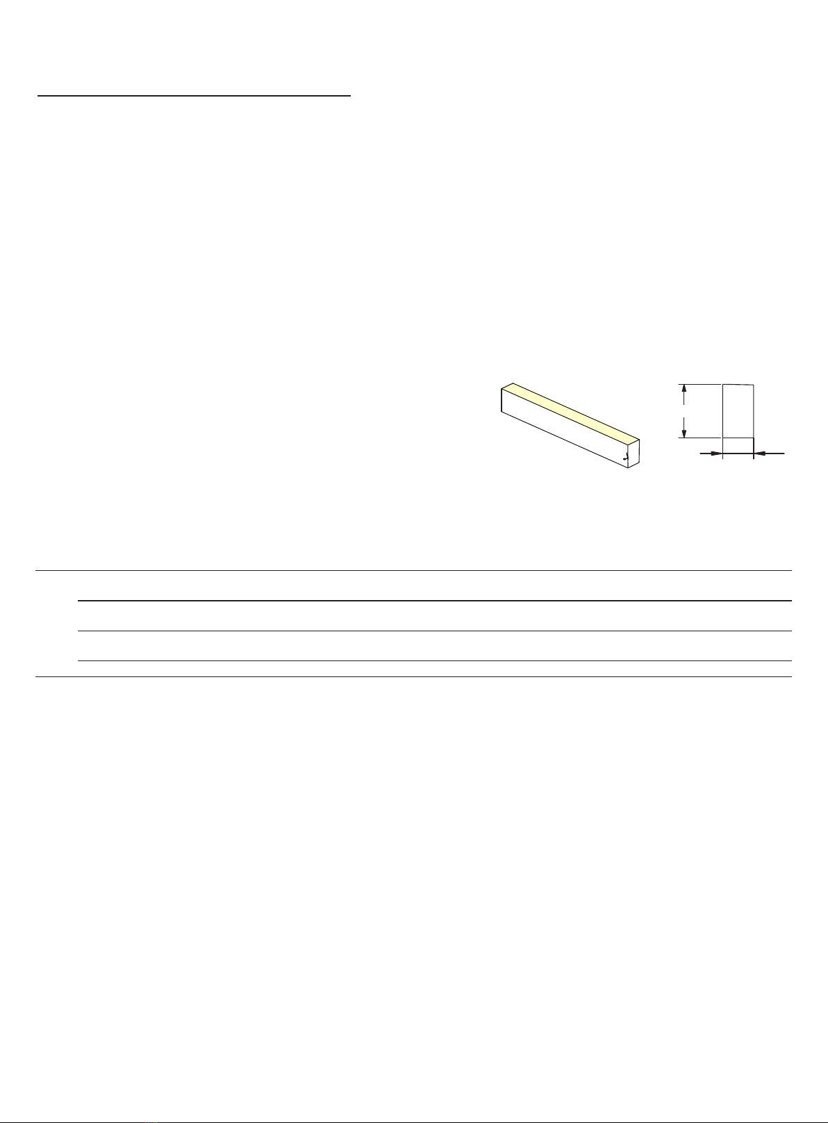
1. Dimension: 9*18mm
2. Min. bend diameter: 90mm
3. Protection rate: IP68/IP67/IP65/IP20
4. IP68 protection rate: Protected against dust and submersion in water (1 meter above).
5.The product IP rate is ultimately in line with properly applied IP rated connectors.
Connector termination required after cutting to achieve appropriate IP Rating.
6. Easy to use, with a range of accessories for joining, terminating, mounting&powering.
7. Long Iifetime: 5 years.
8. Working ambient temperature: -20°C~45°C (High Voltage: -20°C~35°C ) .
9. Environmental Installation Tempeature: 0°C~45°C (High Voltage: -0°C~35°C ).
USER MANUAL www.surelight.com
01
9mm
18mm
Max.Running Length
20m for single end feed
40m for double ends feed
15m for single end feed
30m for double ends feed
7.5m for single end feed
15m for double ends feed
80m for single end feed
Min.Cutting Length
125mm(9LEDs)
83.3mm(6LEDs)
41.7mm(3LEDs)
1000mm(72LEDs)
LED Spacing
13.89mm
13.89mm
13.89mm
13.89mm
Rated Power/m
3.5W
4.5W
4.5W
5W
Working Voltage
D24CV
D24CV
D12CV
Ac230
LED Qty/mtr
72LEDs
72LEDs
72LEDs
72LEDs
Appearance of Cover*
WM
WM
WM
WM
Light Color
R/A
G/B/W
R/A/G/B/W
R/A/G/B/W
B
Light Type: NE-MI
Note: Unless otherwise stated, the tolerance of the light is ±0.3mm.
*
NOTE: Appearance of Cover
1 2
WM=White PVC Housing +Milky Light-emitting Surface
Note 1: Housing color is the light color except from the light-emitting surface.
Note 2: Light-emitting surface color is the color without light up.
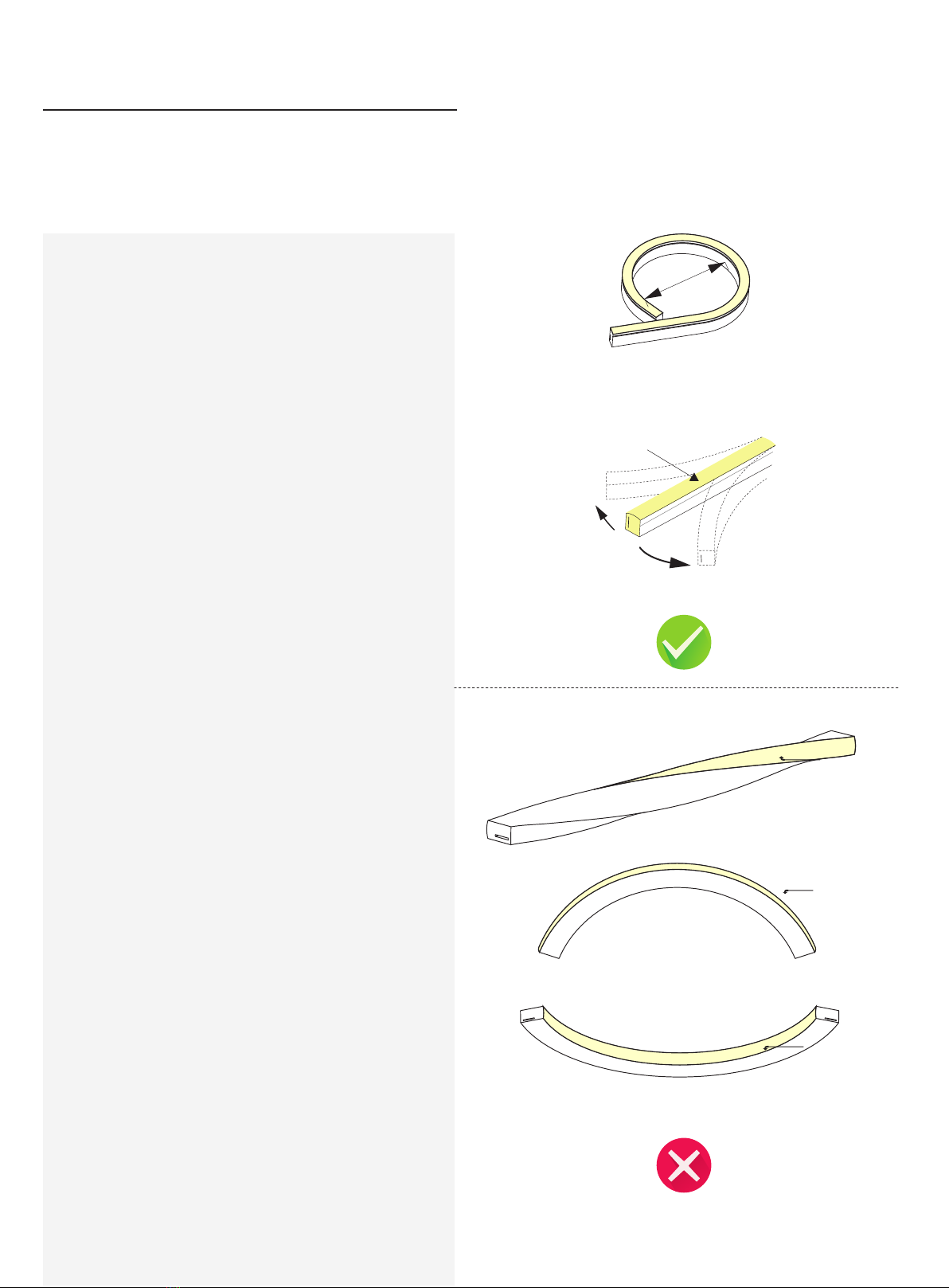
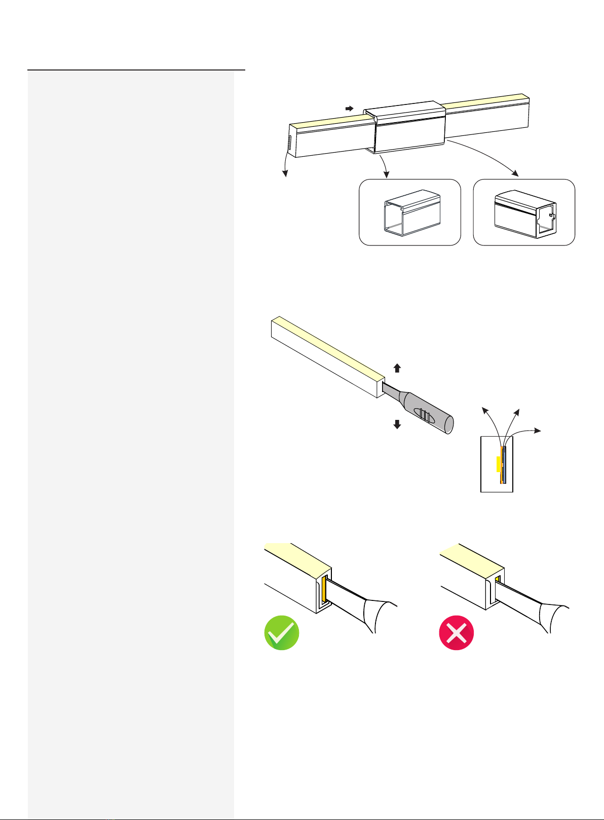
Twist the light
Light Surface
WARNING: The above wrong approaches will damage the light.
Light Surface
Light Surface
Do not bend smaller than allowed minimum bend diameter 90mm.
Cautions
07
USER MANUAL www.surelight.com
1. Before making any cuts, installation, maintenance or
connection, be sure the mains is disconnected!
2. Note: All connectors should be properly installed to achieve
the appropriate level of IP, IP rating can NOT be achieved
without connector termination.
3. Please operate this flex light by instructions, and confirm the
work voltage, it must be matched with product requirements.
4. Please confirm the polarity of connector before insertion front
connection cable.
5. Connect and cut this product correctly. Any wrong operation
will damage this product.
6. Using qualified DC power supply.
7. Please correctly use and bend this flex ribbon light, see the
figures on the right.
8.Do not operate light when ambient temperature exceeds the
range of specified temperature in User Manual.
9.Do not energize the light over 30 minutes in coil packaging.
90 mm
01 |0 2
(HB)Horizontal Bending
Light Surface
Instructions
for
light
cutting
08
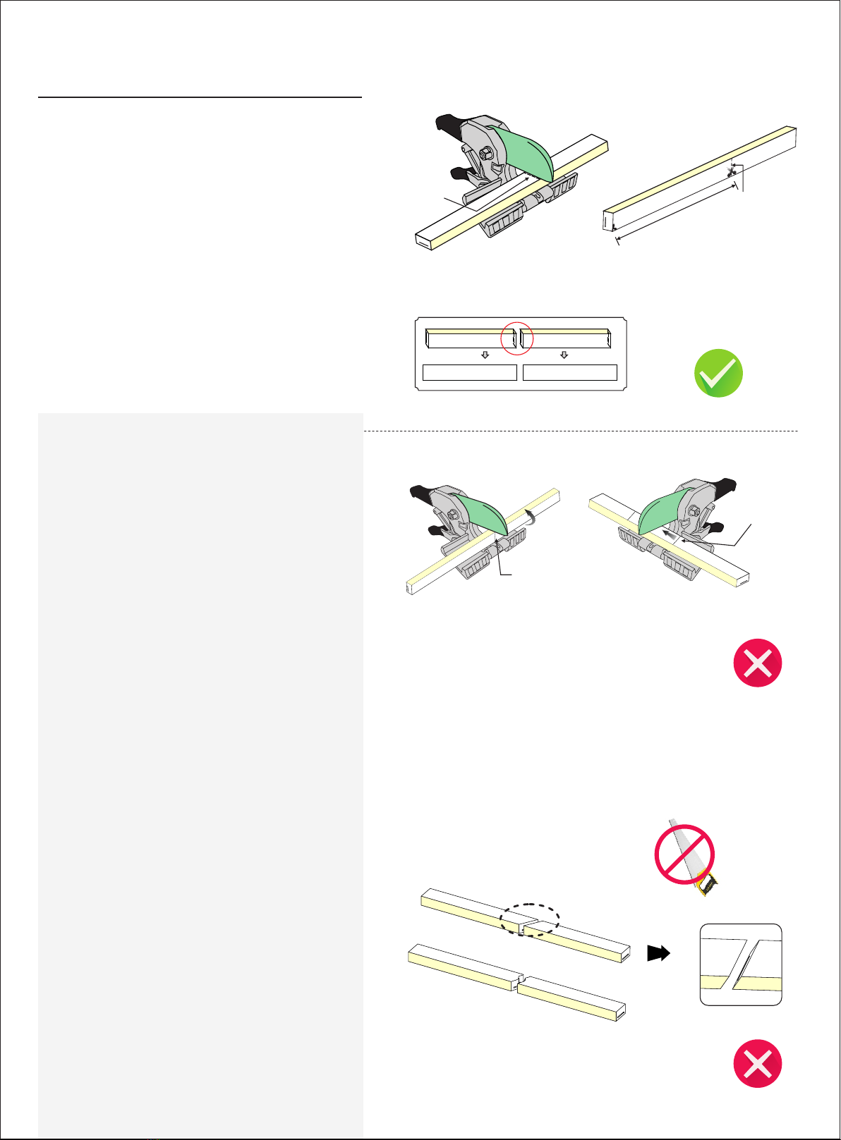
The Min. cutting length
(see as the feature)
Cutting line
Don't cut slantingly
Note:
1. Place the light horizontally when cutting it.
2.Use only factory-recommended cutter.
3.Cut the light according to the following instructions.
Incorrect operation will damage the light
USER MANUAL www.surelight.com
Cutting line
02
01 02
02
Cut the light only at printed cutting line with
printing mark face upwards
The cutting surface must be flush
and smooth.
Printing mark should be faced
upwards
Cutting can only be made at the
printed cutting line
01 0 2
01 0 2
Cutting line
01
Cutting Line
Printing Mark
Please use a smooth and sharp cutter for cutting when the dedicated cutter is not
available, any rusty or jagged cutter is prohibited.
Note: Waterproof may not achieved with the following situations.
09
USER MANUAL www.surelight.com
Clasp Front
Connector
Please ignore these steps if the front
connector has been assembled before
delivery.
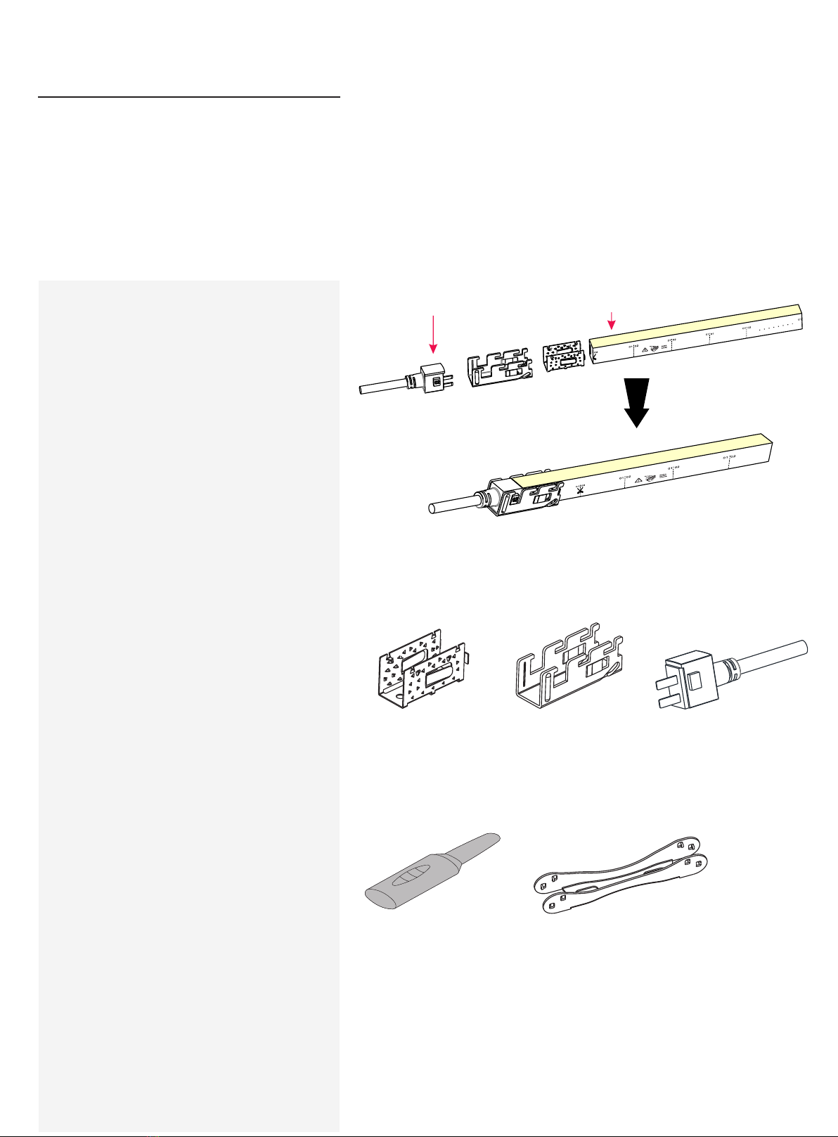
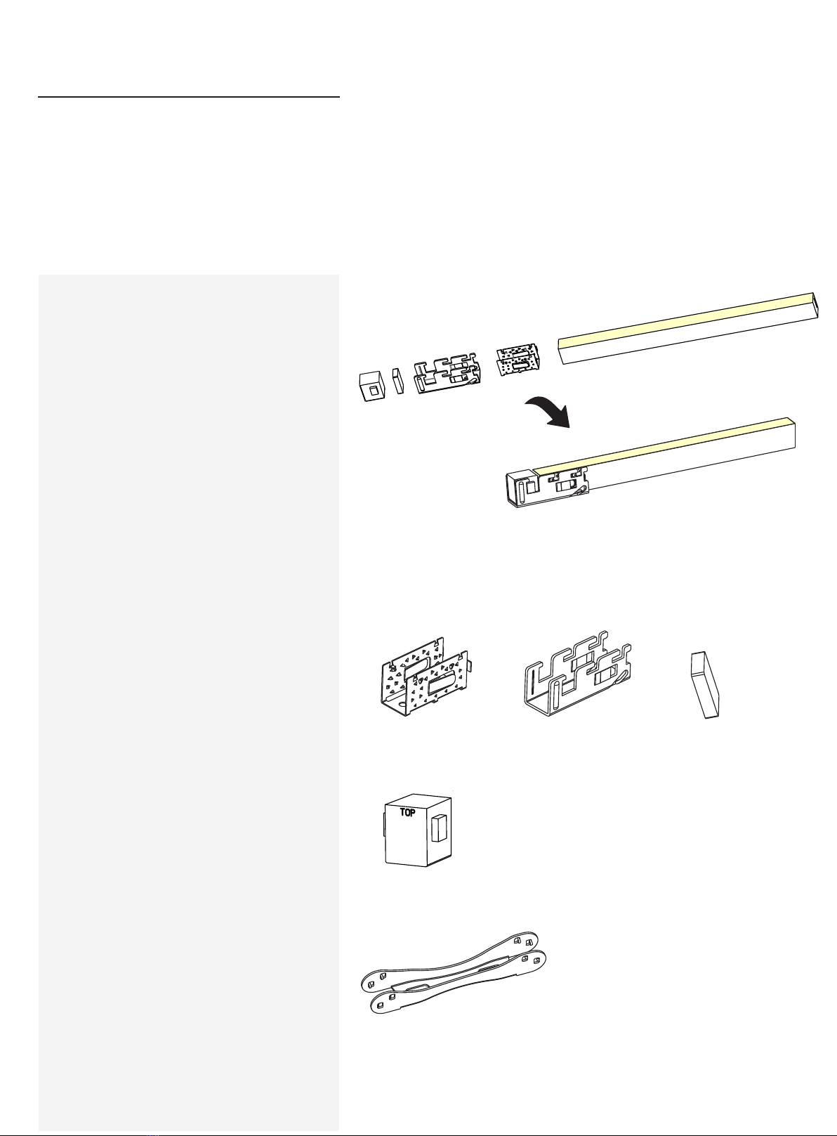
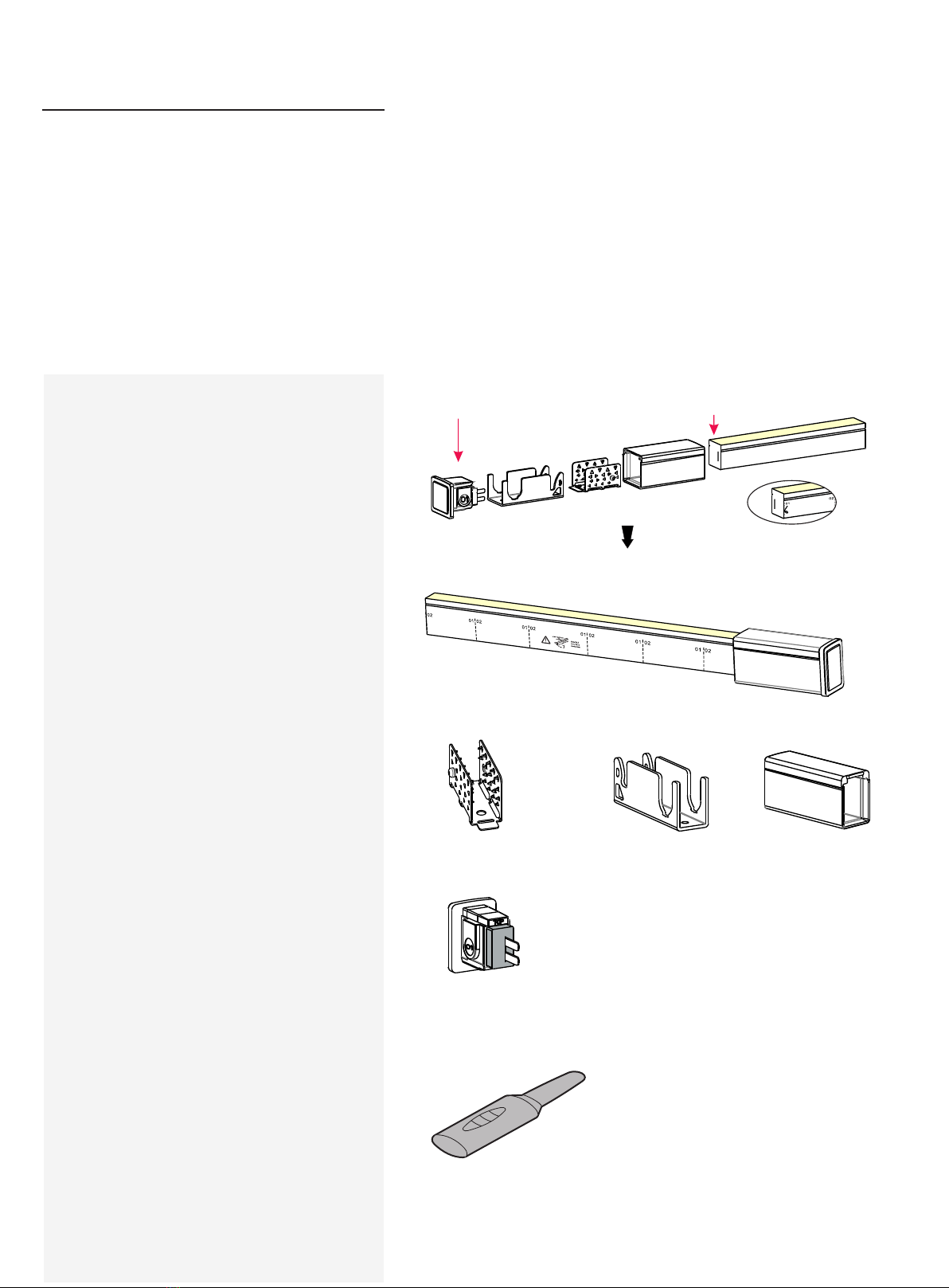
Finished Assembly View
1.Components of Front
Connector
2.Tools
Feed Connector (1pc)
[Contain Silicone Gasket(1pc)]
Anti-skidding Clip (1pc) U Steel Plate (1pc)
Inducer Gripper
Explosive View
02
Note:
1. Never wet the assembly units or assemble with
wet hands.
2. Please use the tools correctly.
3. Please pay attention to personal security when
using tools.
4.Repeated assembly or reuse of the connector may
result in waterproof failure.
Note:
The light ends are marked with either an 01 or an 02. Always
make sure to use an identically labeled connector for the
appropriate direction.
02 Feed Connector 02 End of light
PCB Insertion Placement
PVC Tape
10
USER MANUAL www.surelight.com
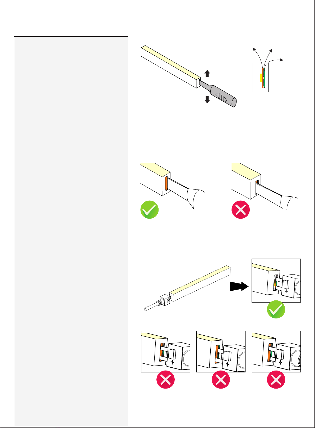
3.Installation Steps
3.1 Inducing a Cavity for Feed Connector
Insert the inducer to the backside of PCB around 10~12mm,
move the inducer up and down 3~5 times gently to create a
small cavity.
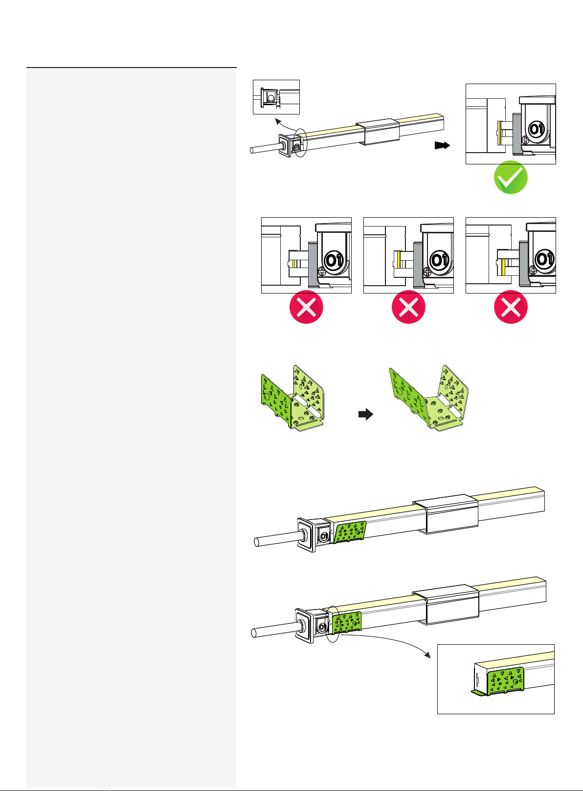
3.2 Insert the Feed Connector
Insert the inducer into the backside of PCB It will damage the light if insert into front
side of PCB
Insert the feed connector pins into the
cavity that you created with the
inducer (backside of PCB)
The following operations are prohibited:
Insert into the front side of the PCB
Insert crosswise into the PCB Insert crosswise into the PCB
NEVER insert into the front side
(LED side) of the PCB
11
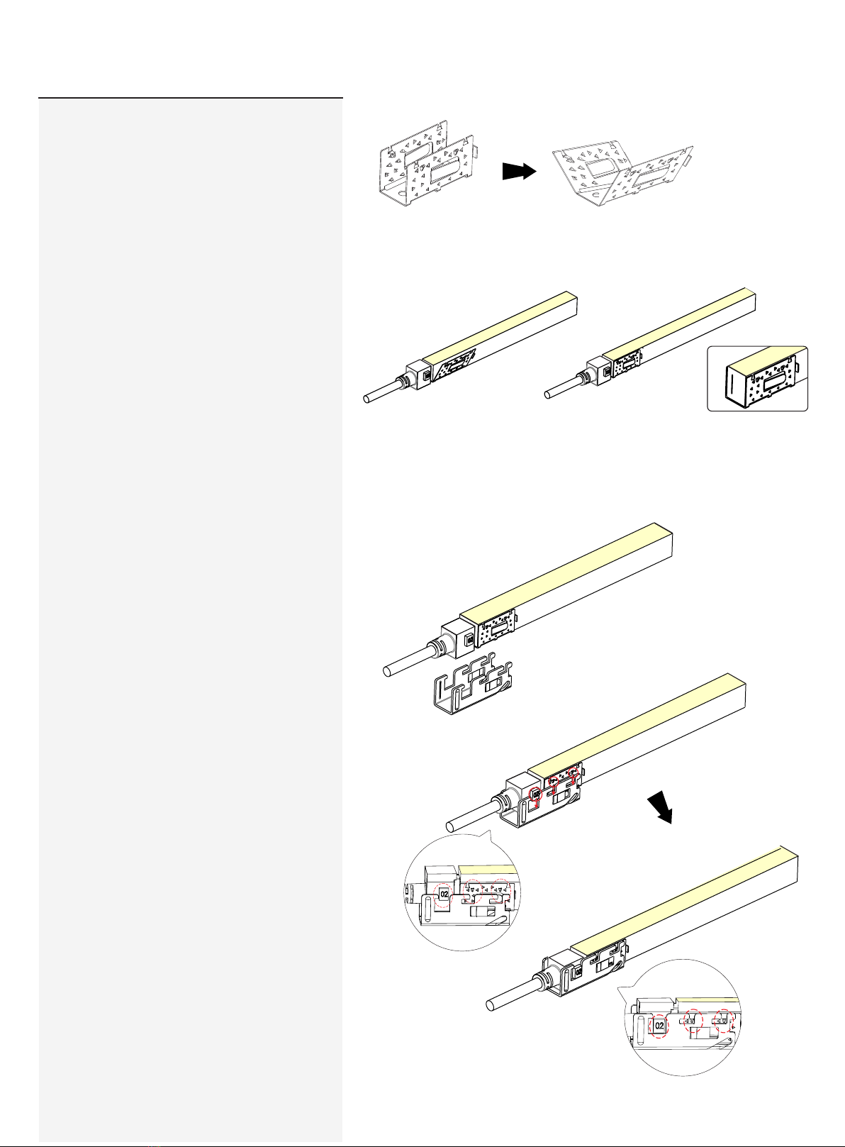
3.3 Treatment of Anti-skidding Clip
Unfold the anti-skidding clip about 20 degrees on both sides.
Fit the anti-skidding clip to the end of the light
tightly and align with the light end edge.
Place the anti-skidding clip
onto the end of the light. Notice
its installation direction.
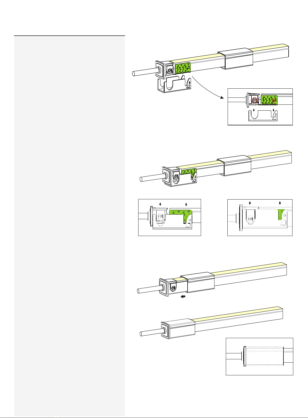
3.4 Installation fo U Steel Plate
USER MANUAL www.surelight.com
Push the bulging points on the anti-skidding
clip into th slots on the U steel plate.
12
USER MANUAL www.surelight.com
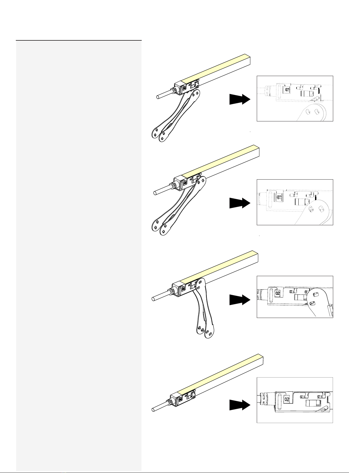
3.5 Push the anti-skidding clip to the end
until the two hook splinters on each side pop
out to lock the U steel plate. Use the gripper
to help tighten the piece.
Please energize the light to check its
functionality and do waterproof
reliablity testing (refer to "waterproof
reliability testing instruction" video)
after connector assembly.
13
USER MANUAL www.surelight.com
Clasp
End Cap
Please ignore these steps if the end cap
has been assembled before delivery.
1.Components of End Cap
2.Tools
Tail Plug (1pc)
Silicone Gasket(1pc)
Anti-skidding Clip (1pc) U Steel Plate (1pc)
Gripper
Explosive View
Finished Assembly View
Note:
1. Never wet the assembly units or assemble with
wet hands.
2. Please use the tools correctly.
3. Please pay attention to personal security when
using tools.
4.Repeated assembly or reuse of the connector may
result in waterproof failure.

14
3.Installation Steps
3.1 Place the tail plug into the U steel plate
USER MANUAL www.surelight.com
3.2 Treatment of Anti-Skidding Clip
Unfold the anti-skidding clip about 20 degrees on both sides.
Place the anti-skidding clip onto the end of the light.
Notice its installation direction.
Fit the anti-skidding clip to the end of the light tightly
and align with the light end edge.
The silicone gasket is attached on the tail plug.

15
USER MANUAL www.surelight.com
3.3. Installation of Tail Plug
Push the bulging points on the anti-skidding
clip into the slots on the U steel plate.
3.4 Push the anti-skidding clip to the end
until the two hook splinters on each side pop
out to lock the U steel plate. Use the gripper
to help tighten the piece.
Please energize the light to check its
functionality and do waterproof
reliablity testing (refer to "waterproof
reliability testing instruction" video)
after connector assembly.

16
USER MANUAL www.surelight.com
Please ignore these steps if the front
connector has been assembled before
delivery.
Snap
Front
Connector
Finished Assembly View
Explosive View
1.Components of Front Connector
Anti-skidding Clip (1pc) PC Cover (1pc)U Steel Plate (1pc)
2. Tools
Inducer
Note:
1. Never wet the assembly units or assemble with
wet hands.
2. Please use the tools correctly.
3. Please pay attention to personal security when
using tools.
4.Repeated assembly or reuse of the connector may
result in waterproof failure.
Note:
The light ends are marked with either an 01 or an
02. Always make sure to use an identically abeled
connector for the appropriate direction.
Feed Connector-top end (1pc) Feed Connector-side (1pc)
[Contain Silicone Gasket (1pc)] [Contain Silicone Gasket (1pc)]
Feed Connector-bottom (1pc)
[Contain Silicone Gasket (1pc)]
02 Feed Connector 02 End of light
Pay attention to the direction marked on the
bottom of PC cover.
17
3.2 Inducing a Cavity for Feed Connector
Insert the inducer to the backside of PCB around 10~12mm,
move the inducer up and down 3~5 times gently to create a
small cavity.
Insert the inducer into the backside of PCB It will damage the light if insert into front
side of PCB
NEVER insert into the front side
(LED side) of the PCB
3.1 Placing PC Cover
3.Installation Steps
Snap end of PC Cover Rear end of PC Cover
The assembly end
USER MANUAL www.surelight.com
PCB Insertion Placement
PVC Tape
18
The following operations are prohibited:
Insert into the front side of the PCB
Insert crosswise into the PCB Insert crosswise into the PCB
It will be a 2~5mm gap.
Unfold the anti-skidding clip about 20
degrees on both sides.
Place the anti-skidding clip onto the assembly end of the light.
Pay attention to its direction
Fit the anti-skidding clip to the end of the light so that it wraps
tightly and its brim is aligned with the cut edge on both sides.
3.3 Inserting the Feed Connector
3.4 Treatment of Anti-skidding Clip
3.5 Installation of Anti-Skidding Clip
USER MANUAL www.surelight.com
W=2~5mm
19
Slide back the PC cover till it snaps
in the feed connector.
Press the feed connector and light
downwards at the same time till
bottom.
Align the feed connector and anti-
skidding clip with the U steel
plate.
3.6 Installation of U Steel Plate and PC
Cover
Please energize the light to check its
functionality and do waterproof
reliablity testing (refer to "waterproof
reliability testing instruction" video)
after connector assembly.
USER MANUAL www.surelight.com
20
Please ignore these steps if the End Cap
has been assembled before delivery.
Snap
End Cap
Finished Assembly View
Explosive View Printing on opposite side of light
1.Components of End Cap
2. Tools
Tail Plug (1pc)
[Contain Silicone Gasket (1pc)]
Anti-skidding Clip (1pc) U Steel Plate (1pc) PC Cover (1pc)
Inducer
USER MANUAL www.surelight.com
Note:
1.Repeated assembly or reuse of the connector may
result in waterproof failure.
01 End Cap 01 End of light
Table of contents
Popular Outdoor Light manuals by other brands

B-K lighting
B-K lighting TENAYA2 Series Housing Installation

Livoo
Livoo TEA247 user manual

Coopers of Stortford
Coopers of Stortford Solar Bird Welcome Stone Instructions for use

Pro-Elec
Pro-Elec PEL00589 instructions

Zafferano
Zafferano poldina XXL quick start guide

Renkforce
Renkforce 1005226 operating instructions

GLUCKSTEIN ELEMENTS
GLUCKSTEIN ELEMENTS 39643-HBCLED Use and care guide

SLV Elektronik
SLV Elektronik KALU FLOOR 1 operating manual

Panlux
Panlux GARD NOO-E14 instructions

Hubbardton Forge
Hubbardton Forge Erlenmeyer Dark Sky Assembly/installation instructions

Lucci decor
Lucci decor Ava LD-F59469S-SI installation instructions

Maxim Lighting
Maxim Lighting Clyde VX manual


