4
lci1.com 574-537-8900 Rev: 01.05.21
SureShade®
Power Bimini
Sport Arm Kit
Installation and Owner’s Manual
(For Aftermarket Applications)
CCD-0003954
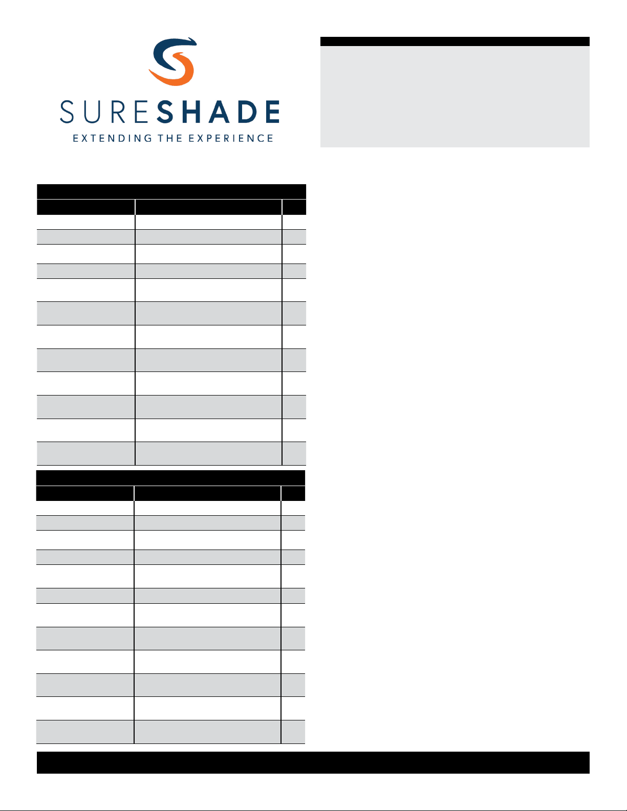
32” Bimini Front Support Kit PN 2020134626 - Blk32” Bimini Front Support Kit PN 2020134626 - Blk
LetterLetter PNPN DescriptionDescription QtyQty
A 853947 1/4” - 20 x 1 1/2” PHIL TRUSS MS SS 2
B 853950 Barrel Nut with Loctite®,1/4” - 20 x 1/2” 2
C 853970 H-Bracket Plastic Pivot Bushings 4
D 853966 End Cap - 1.25” SQ 2
E 854135 Bracket,1.25” (h) x 1.490” (w), Blk
Anodized (Type II)
2
F 2020000071 EZ Install SQ Tubing Clip (1.25”), Blk 2
G 2020102622 SQ Eye End Fitting, Stainless
Anodized (Type II)
2
H 2020104192 Tube, 1.25” x 1.25” x 0.063”, 32” (lng),
Blk Anodize
2
I 2020104413 Quick Release Bimini Top Hinge
Assembly
2
J 853943 Screw, #10 - 32 x 1/4” TRH PSV PH
FT SST
4
K 853953 Screw, #10 x 3/4”, Zn RD HD,
Self-drilling
6
L 853954 Screw, 1/4” - 14 x 3/4”, HWH PSV
Hex SLFDR SST
2
32” Bimini Front Support Kit PN 2020134625 - Clr32” Bimini Front Support Kit PN 2020134625 - Clr
LetterLetter PNPN DescriptionDescription QtyQty
A 853947 1/4” - 20 x 1 1/2” PHIL TRUSS MS SS 2
B 853950 Barrel Nut with Loctite®,1/4” - 20 x 1/2” 2
C 853970 H-Bracket Plastic Pivot Bushings 4
D 853966 End Cap - 1.25” SQ 2
E 854136 Bracket,1.25” (h) x 1.490” (w), Clr
Anodized (Type II)
2
F 861714 EZ Install SQ Tubing Clip (1.25”),
Gray
2
G 2020102622 SQ Eye End Fitting, Stainless
Anodized (Type II)
2
H 2020104193 Tube, 1.25” x 1.25” x 0.063”, 32” (lng),
Clr Anodize
2
I 2020104413 Quick Release Bimini Top Hinge
Assembly
2
J 853943 Screw, #10 - 32 x 1/4” TRH PSV PH
FT SST
4
K 853953 Screw, #10 x 3/4”, Zn RD HD,
Self-drilling
6
L 853954 Screw, 1/4” - 14 x 3/4”, HWH PSV
Hex SLFDR SST
2
Resources Required
• 1 - 2 people, depending on the task
• Electric or cordless drill or screw gun
• Phillips head screwdriver (2)
• Phillips head drive bit
• ⁄” hex drive socket
• Tape measure
• Non-permanent method of marking
Preparation
Prior to ordering the desired kit, determine the proper size
(length) of the support tube required to adequately meet
the pontoon’s structure and floor plan.
1. With the frame assembly in its fully extended position,
take a vertical measurement from the at surface of a
railing to the front strut on the side of the boat that may
have an obstruction, such as a door or seat, that may get
in the way of the front sport arms.
NOTE: The actual position of the sport arm tube may have
to move forward slightly to provide a ⁄” gap between the
tube’s edge and the front strut (Fig.1).
2. If the measurement is 34”-38”, or greater, use 36”
sport arms.
NOTE: For the 36” sport arms, use 38” total as a guide for
the added hardware
3. If the measurement is 32”-34”, or less, use 32”
sport arms.
NOTE: For the 32” sport arms, use 34” total as a guide for
the added hardware
Use 36” sport arms if possible. The longer the sport arms
that are used, the more strength will be added to the front
frame. If not possible, use the 32” sport arms to achieve
the recommended added strength to the front frame.
Make sure to order the color that matches the frame;
• clear (silver) or
• black.