Surgival Genutech CCK User manual

Surgical Technique
Genutech®CCK total knee revision system


SURGICAL TECHNIQUE
1. TIBIAL TIME (I) 2
1.1 Intramedullary fixation 2
1.2 Assembly and fitting of the tibial cutting guide 4
1.3 Tibial resection 7
1.4 Measuring of the tibial tray 8
1.5 Measuring of the interline 9
2. FEMORAL TIME 10
2.1 Measuring of the femoral component 10
2.2 Intramedullary fixation 11
2.3 Distal cut 14
2.4 Femoral cuts 15
2.5 Verification of stability during flexo-extension 20
2.6 Reaming to house the femoral post 21
2.7 Assembly of the trial femoral component 23
3. TIBIAL TIME (II) 24
4. MOBILITY / STABILITY CHECK 29
5. PATELLA TIME 30
6. FINAL IMPLANT 31
ANNEXES 32
IMPLANTS AND INSTRUMENTS 44
Table of contents

2
1. TIBIAL TIME (I)
1.1 Intramedullary fixation
Diaphyseal intramedullary reaming
To ensure good stability on the diaphyseal axis of the reamer, which serves as a guide and support during surgery, intramedullary reaming is performed,
with a depth according to the length of the stem which is going to be used.
Diameter of the reaming: The recommended diameters for this reaming are normally around Ø9-10 or 11mm, although the suitability of the final
diameter for the tibial diaphysis to be used is always at the discretion of the surgeon and, through gradual reaming, it may even be close to that
of the inner cortex diameter fitting. This is the case when a 200 mm stem must be inserted.
Depth: Generally, the diaphyseal reamer is inserted up to the second 70-120-200 mark, because at this depth greater stability, accuracy, tighte-
ning and safety are achieved for the installation of the tibial cutting guide. If it is not possible to penetrate this deeply (short tibia, fracture callus
which closes the medullary cavity…), at a minimum it must penetrate as far as the 70 mark in order to house a stem which is 70 mm long.
The diameter and depth are marked on the axis of the diaphyseal reamer, and as the tibial time is being performed, depths must be adjusted according
to the marks close to the initial T, depending on the length of the tibial stem (70, 120 or 200 mm) which you intend to implant.
Surgical Technique
Set 0. Upper tray

3
Intramedullary reaming guided by cannulated reamers
During this step use the stem of the diaphyseal reamer as a guide.
Depth: In order to install the 70 mm stem, ream until the first 70 mark is level with the tibia surface and if, on the other hand, the stem must be
102 or 200 mm, ream until the second 120-200 mark.
Diameter: Carry out gradual reaming in order to carve the cavity which will house the tibial stem.
Note:
When using a 200 m stem, the diameters of the reamers (diaphyseal and cannulated) will be the same, because in order to reach a reaming depth of
200 mm, you use part of the length of the reaming which has already been completed to secure the diaphyseal reamer.
(See other examples of intramedullary reaming according to the length of the stem being implanted in Annex I)
Cavity reamed
to house
tibial stem
Set 0. Lower tray

4
Insertion of the metaphyseal sleeve
Once the guided cannulated reaming has been completed at the chosen depth, insert a metaphyseal sleeve to ensure that there is the necessary sta-
bility to secure the cutting guides, thus ensuring optimal cutting accuracy and congruency in how the tibial tray is positioned in relation to the stem.
The diameter of the sleeve being used is the same as the diameter of the last cannulated reamer which was used, installing a short metaphyseal sleeve
if the reaming was performed in order to insert a 70 mm stem, or a long one if reaming has reached the second mark (120-200) to insert a 120 or 200
mm stem.
The sleeves must be inserted with the revision sleeve inserter/extractor at a minimum depth, as indicated on the axis of the inserter, according to the
readings which correspond to the surgical time we are performing (tibia or femur) and the type of surgery being carried out (Semi-Constrained Revision
“REV” or Primary Semi-Constrained “PRIM”).
1.2 Assembly and fitting of the tibial cutting guide
Assembly of the tibial cutting guide
After performing intramedullary fixation of the reamer with the help of the metaphyseal sleeve, on the protruding stem assemble the telescopic guide
system with the corresponding tibial cutting guide (right or left), distally clamping it to the patient’s ankle with the help of the distal clamp for the
tibial guide.
Surgical Technique
Set 0. Lower tray
Set 0. Upper tray

5
Tibial cutting
guide
Telescopic
guide system
Tibial clamp
Fixation
screws
Tibial
cutting guide
Graduation for
displacement control
Transverse connector
Fitting of the tibial cutting guide
On the tibial cutting guide there is a threaded displacement measuring system, which allows you to have strict control over the steps we take. This
system must be adjusted into position 0 before it is used.
In order to find reference “0”, insert the probe hook into the standard cutting slot (slot “0”) and the whole system travels on the axis of the reamer, until
the tip of it rests on the most prominent area of the tibia.
In this position tighten the blocking screws or fixation screws of the transverse connector and of the telescopic guide, and then install the revision probe.
Transverse connector
Blocking
screws
Slot “0”
Reference “0”
Probe hook

6
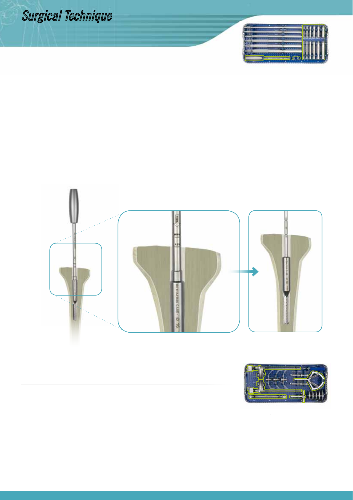
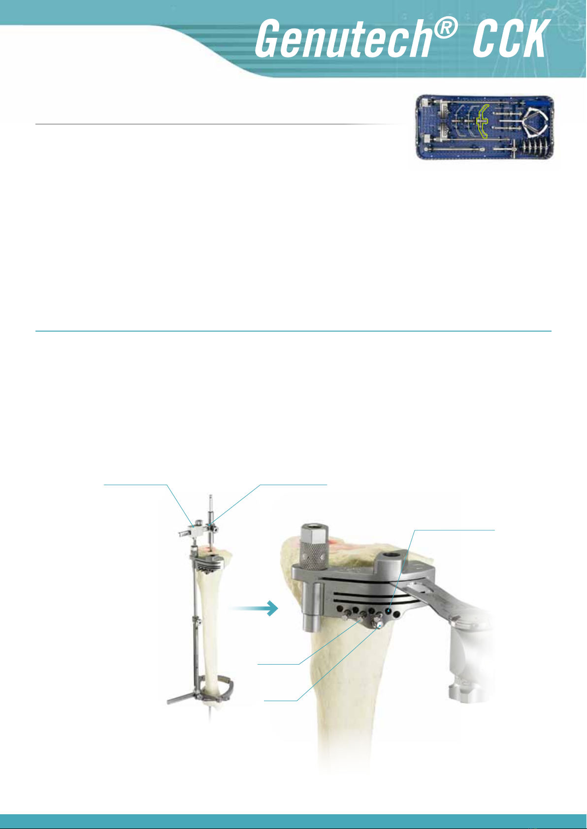
Installation of the revision probe of 0-8 or 0-12 mm
In the most favourable cases, where you only need to make a thin cut to sanitise the tibial
surface, with the “0” end (short arm) of the probe, look for the most depressed area of the
tibial plateau to ensure that the cut being made is always below said point. To do this you
must use the threaded displacement measuring system to move it down until it rests on said
area. Once the most depressed area has been reached, fix the tibial cutting guide and then
make the cut.
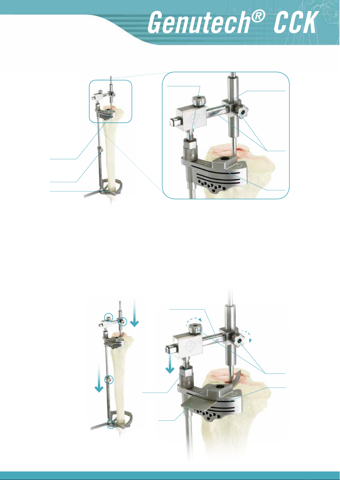
In extreme cases, in which the tibia is extremely damaged, a prosthesis has been replaced
with supplements or it is necessary to sanitise a bone which is significantly (8 mm, 12 mm,
etc.). Using supplements, in the medial, lateral or even the bilateral area, proceed as follows:
The ”0” end (short arm of the tibial probe) must be directed towards the most depressed
area of the most prominent tibial plateau. To do this you must use the threaded displacement
measuring system to move it down until it is rests on said area.
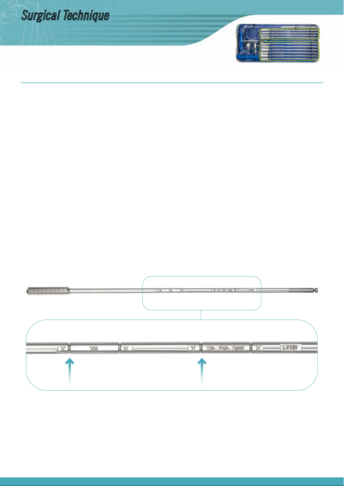
Then note down the amount of millimetres which the system has gone down (see measure-
ment on the graduated marks on the telescopic guide).
With the arm of the rod in position “8” or “12” probe the most depressed area of the plateau
with the most wear, and the following situations may arise:
a) The 8 mm arm of the “0-8” probe does not fit
In this case cut to +8 and install an 8 mm tibial supplement below the tibial tray
on that side.
b) The 8 mm arm is not in contact
In this situation, assemble the “0-12” probe, trying to ensure contact with its
12 mm arm, and the following situations may arise:
b1) The 12 mm arm does not fit, leaving two options:
· Move it down with the sheave of the tibial cutting guide until the 8 mm arm
touches the area with the most wear, making a +8 mm recut in that area. In this
situation there will be additional displacement with the sheave to transfer it to
the thickness of the tibial insert (to maintain the interline), and an 8 mm tibial
supplement will be used in the aforementioned most depressed area.
· Keep the cutting guide in its initial position and recut +12 on the plateau with
most wear, using a 12 mm tibial supplement.
b2) The 12 mm arm is not in contact
Move down the threaded displacement measuring system to the 12 mm arm, ma-
king a +12 recut in the most depressed area to use a 12 mm tibial supplement.
You must also take into account the amount of millimetres which the cutting guide
has moved downwards with the threaded displacement system and add them to
the thickness of the tibial insert and ensure that the interline is maintained. Note:
Move the system down until the probe touches the ti-
bial plateau.
Surgical Technique
Set 1. Upper tray

7
PRIMARY TIBIAL SURGERY
When performing primary tibial surgery by implanting a semi-constrained prosthesis tibial component, install the “0-10” rod on the tibial cutting guide.
Firstly, the “10” end of the probe must be directed towards the most depressed area of the most prominent plateau and then, with the arm of the rod
in position “0”, probe the most depressed area of the plateau with the most wear. If in order to probe on the most depressed plateau it is necessary to
move the system down, this measurement must be noted down.
Note:
For the “0-10” rod, which is only used for primary semi-constrained surgery, the “0” probe coincides with the deepest point of the rod, unlike the “0-8”
and “0-12” rods used for revision surgery.
1.3 Tibial resection
Once the tibial cutting guide is in the correct position, it is fixed to the tibia using pins. Then the telescopic intramedullary system is removed (loose-
ning all of the fixation screws, moving to the end of the stroke of the thread of the tibial cutting guide and pulling up the telescopic system), and the
intramedullary system is removed.
This is when the tibial cut is made.
First line of
parallel pins
Oblique pin
Second line of parallel pins
for “Recut +2”
Extramedullary system Intramedullary system
Set 1. Upper tray

8
Note:
· Should there be any difficulties when removing the intramedullary system because of an obstructing metaphyseal sleeve, this can be reamed with the
tip of the sleeve inserter/extractor and it can be released by tapping it outwards.
· It is recommended to insert the parallel pins on the first line of pins, using at least three pins and one oblique pin to ensure effective fixation.
· It is recommended that you first put in place the pins at both ends, so that the central pins do not impede the removal of the intramedullary compo-
nents and then, once the intramedullary system components have been removed (diaphyseal reamer and metaphyseal sleeve), install the central pins.
· The parallel pins can be kept, by way of a reference point, to make it possible to make the 2 mm recut.
· If after removing the pins we want to recover this reference point, it is recommended to put back the cutting guide by inserting the probe hook through
the corresponding cutting slot, supporting it on the resected surface and making use of the drill holes which have already been made in order to reinsert
the pins and thus fix the cutting guide in the right position. For greater accuracy when putting back the cutting guide it is recommended to perform the
above action by reassembling the extramedullary telescopic system on the intramedullary system.
1.4 Measuring of the tibial tray
After making the cut, when placing the trial templates on the tibial cut, select the size which best suits the bone morphometry of the tibial cut which
has been made.
Trial tibial template
Support handle
Surgical Technique
Set 1. Upper tray

9
In order to measure the interline, fit the lower edge of the interline sizing guide’s flange onto the ATT. As the average interline ranges approximately from
25 mm (Size 1: 23 mm, Size 2: 24 mm… Size 5: 28 mm) it is possible to determine the thickness of the tibial insert to be used in advance in order to
maintain the articular interline.
Note:
When it is necessary to perform an osteotomy of the TTA to make it possible to dislocate the patella, the height of this insertion will be marked on the
front side of the metaphysis so that measurements can be taken from this mark.
It is essential that the interline is located in the right place in order to ensure proper knee function.
Example:
If “a” is the height from the insertion of the patellar ten-
don with the ATT to the tibial osteotomy, and knowing that
the thickness of the tibial tray is approximately 4 mm and
the interline is approximately 25 mm from the insertion of
the patellar tendon with the ATT, we can conclude that the
thickness of tibial insert “I” to be used must be as follows
in order to maintain the interline:
Therefore, a 10 or 12 mm tibial insert would be used to
maintain the interline in its position.
Interline
Tibial Tray
Tibial Cut
1.5 Measuring of the interline
Set 2. Upper tray
Thickness of Insert:
(see image)

10
2. FEMORAL TIME
2.1 Measuring of the femoral component
Revision surgeries: using revision femoral sizing guides.
Let us consider two situations:
a) Implantation of a semi-constrained TKR on a knee with no previous surgery (primary surgery).
b) Implantation of a semi-constrained replacement in a prosthetic replacement (revision surgery).
Primary surgeries: using the primary femoral sizing guide which will indicate the correct size, supporting the posterior condyles and tapping with the
rod on the anterior cortex. In this case the sizing guide is inserted with the diaphyseal reamer through the centring sleeve. So for primary surgeries,
ream with the diaphyseal reamer and then measure the size of the femoral component.
Note:
· At this moment, check and assess the size which was
previously selected for the tibia (see 1.4.)
· When the sizing gauge is positioned between two sizes,
the smaller size must be selected.
Surgical Technique
Set 2. Upper tray

11
2.2 Intramedullary fixation
Diaphyseal intramedullary reaming
In order to ensure good stability for the axis of the diaphyseal reamer, which serves as a guide and support during surgery, gradual intramedullary
reaming is performed with a depth according to the length of the stem which is going to be used.
Diameter of the reaming: The recommended diameters for this reaming are normally around Ø9-10 or 11 mm, although the suitability of the final
diameter for the femoral diaphysis to be used is always at the discretion of the surgeon and, through gradual reaming, it may even be close to that
of the inner cortex diameter fitting. This is the case when a 200 mm stem must be inserted.
Depth: Generally, the diaphyseal reamer is inserted up to the second 70-120-200 mark, because at this depth greater stability, accuracy, tighte-
ning and safety are achieved for the installation of the femoral cutting guide. If it is not possible to penetrate this deeply (short femur, fracture
callus which closes the medullary cavity…), at a minimum it must penetrate as far as the 70 mark in order to house a stem which is 70 mm long.
As the femoral time is being performed, the depths must be adjusted to the marks close to the initial F, as indicated in the image below.
Reaming guides with cannulated reamers
Deciding the length of the stem which is going to be used prior to the operation, ream with a cannulated reamer to the depth which was chosen, reaming
with an incremental diameter.
Depth: To install a 70 mm stem, penetrate as far as the first 70 mark. If, on the other hand, the stem must be 102 or 200 mm, ream until the second
120-200 mark. As this is the femoral time, pay attention to the depth marks closest to the initial F.
Set 0. Upper tray
Set 0. Lower tray

12
F-70 F-70
Diameter: Carry out gradual reaming in order to carve the cavity which will house the femoral stem.
Cavity to house
stem
Note:
When using a 200 m stem, the diameters of the reamers (diaphyseal and cannulated) will be
the same, because in order to reach a reaming depth of 200 mm, you use part of the length of
the reaming which has already been completed to secure the diaphyseal reamer.
(See other examples of intramedullary reaming according to the length of the stem being
implanted in Annex I)
Set 0. Lower tray
Surgical Technique

13
Insertion of the metaphyseal sleeve
Much like for the tibial time, in order to give the system greater possible stability for subsequent assemblies and surgeries, a metaphyseal sleeve is
installed, occupying the position which has been machined with the cannulated reamer and which is subsequently occupied by the femoral stem.
The diameter of the sleeve being used is the same as the diameter of the last cannulated reamer which was used, inserting a short metaphyseal sleeve
if the reaming was performed up to the 70 mark, or a long one if reaming has reached the 120-200 mark.
The sleeves must be inserted with the revision sleeve inserter/extractor, with its threaded cap which protects the extracting thread, at a minimum
depth, as indicated on the axis of the inserter, according to the readings which correspond to the surgical time we are performing (femur) and the type
of surgery being carried out: Semi-Constrained Revision or Primary Semi-Constrained.
Note:
It is recommended to insert the sleeve with its threaded cap (to protect the extracting thread).
When inserting a sleeve of Ø10 mm the inserter must be used without the cap because if this protective cap is used it will exceed the 10 mm
diameter of the sleeve.
Set 0. Lower tray

14
2.3 Distal cut
On the axis of the diaphyseal reamer insert the distal cutting mask, which has been installed on the 5° angular guide which crosses the axis.
Then insert the mask until it comes into contact with the distal part of the femur, supporting the mask’s upper visor on its front and secure with threa-
ded pins of Ø 4.4 mm.
Two options can be seen on the cutting mask, which are marked on the cutting slots. Through these you will take into account the readings on the left
to perform “Primary Semi-Constrained” surgery and those on the right for “Semi-Constrained Revision” surgery.
In the case of “Primary” surgery, cut the support area to 8 mm, and for “Revision” surgery cut to 1 mm. We will also find slots marked for additional
recuts of 4, 8 and 12 mm, to enable sanitising or on condylar cuts. In these cases we will use distal supplements with the same thickness as the distal
cut which has been made.
Note:
Before fitting the mask and making the cuts it is advisable to take into account its degree of rotation, perpendicularly aligning the mask with
the tibial axis. This is performed by inserting the “Alignment Bar” through the hole of the “5° Angular Guide”, aligning it with the “tibial crest”.
Alternatively, the mask can also be guided using the femoral epicondyles.
Set 2. Upper tray
Surgical Technique

15
2.4 Femoral cuts
Positional adjustment of femoral cutting mask
Remove the distal cutting mask and the angular guide and set up the reamer with its sleeve. Place the cutting guide of the previously selected size on
the handle of the reamer (see 2.1) with the insert positioner and the concentric positioner.
A “Revision” or “Primary” rod has been fitted onto the cutting guide, depending on the type of surgery. Then check whether or not the rod is resting on
the anterior cortex.
REVISION
rod
PRIMARY
rod
If it is being supported offsetting is not necessary. If it is not being supported remove the concentric positioner and put the eccentric positioner in its
place, rotating it to the left or right until the rod is resting on the frontal area of the femur.

16
Once the rod is touching it, externally rotate the cutting mask by 3°.
Note I:
The medial-lateral displacement resulting from this off-
setting must be carried out as deemed appropriate by
the physician, seeking to centre the femoral component,
although it must be noted that rotating towards the ex-
ternal part has the advantage of reducing the tension on
the patella and is conducive to it being centred on the
femoral component.
Note II:
The cutting mask has housings for 4, 8 and 12 mm dis-
tal supplements, which must be installed to provide pro-
per distal support to the cutting mask, mainly in those
cases where recuts have been necessary on the distal
condyles.
3° of external rotation
With the knee at 90° flexion, and the posterior condyles resting on the surface of the tibia which has previously been cut, insert the 3° external rotation
system into the posterior cutting slots of the cutting guide.
Fit the alignment bar into the hole 3° to the left or right. When this bar is aligned with the axis of the tibia, externally rotate the cutting guide by 3°.
This support also has a hole at 0° which may be used at the discretion of the surgeon.
Surgical Technique
Set 3.

17
Reading of the offset
In this position the offset reading is taken, if an offset has been necessary, because the stem must be fixed to both the trial and final femoral
components.
To take this reading it is important to pay attention to the number of the insert positioner which coincides with the mark of the eccentric positioner.
Alignment
bar
Tibial axis
Alignment of bar with
tibial crest

18
Fixation of the cutting mask with threaded pins
Subsequently, secure the cutting mask to the femur with threaded pins of Ø 4.4 mm and then remove the rod, the concentric or eccentric positioner, the
insert positioner, the metaphyseal sleeve and the diaphyseal reamer.
Note:
It is recommended to insert the thread as far as possible, only leaving one or two threads outside the cortex to ensure that the system has optimal
fixation and stability. The pins have a reference slot which indicates the maximum depth to which the pins should be inserted to avoid problems
when extracting the diaphyseal reamer and the sleeve from inside the intramedullary axis.
If we are making a 12 mm distal recut, the fixation of this condyle will be unstable if we only insert the pin as far as the slot, because only the tip
of the pin will reach the bone. If it is inserted deeper, this will present an obstacle when removing the diaphyseal reamer and sleeve. Therefore, it
is recommended to initially insert the pin as far as the slot and, once the intramedullary components have been removed, finish inserting the pin
until it penetrates the threaded area of the bone.
Making femoral cuts
Fit the appropriate cutting insert for the size of the femur and use it to make frontal, rear and bevel cuts.
Note:
The cutting mask makes it possible to make subsequent
additional cuts at 4 and 8 mm.
To facilitate the identification and correspondence between
sizes of masks and their corresponding cutting inserts, the-
re are colour markers which also coincide with the colour
which will subsequently be used for the trial tibial insert for
the flexo-extension test.
Set 3.
Surgical Technique
Table of contents
Popular Medical Equipment manuals by other brands

OncoTherm
OncoTherm EHY-2000plus user manual

Arthrex
Arthrex SynergyRF AR-9800 Service guide

ResMed
ResMed Astral 150 Information and User Guide for Qualified Professionals

Siemens
Siemens VB 13C quick guide

Precision Medical
Precision Medical Easy Go Vac PM66 Series user manual

Sirona
Sirona Heliodent plus operating instructions