manuals.online logo
Brands
  1. Home
  2. •
  3. Brands
  4. •
  5. Surveillix
  6. •
  7. Media Converter
  8. •
  9. Surveillix ENC-8CH User manual

Surveillix ENC-8CH User manual

QUICK START GUIDE
ENC-8CH / ENC-16CH
Analog to IP Encoder
This quick start guide is a reference for users to install and operate their
encoder and provides basic information on the encoder’s settings and op-
eration. Before attempting to connect, congure and operate the encoder,
please read this document thoroughly.
Video Looping
Out 1 Video looping out
Video In (BNC) 2 Video input streams from cameras (4/8/16)
Power Supply 3 DC12V power supply
LAN 4 LAN connection for network and browser support
HDMI Output 5 HDMI input for monitor connection
Alarm I/O and
RS-485 6 Alarm and RS-485 input/output for external devices
Audio (16CH
only) 7Audio input for connection with audio devices, audio output for
monitor
• H.264 video compression
• 30 IPS @ 960H
• Alarm I/O
• Rack and wall mount brackets included
• Looping outputs
• HDMI spot monitor output
CONNECTIONS
8/16CH Front
DC 12V
LAN
HDMI
AUDIO
ALARM I/O
DC 12V
LAN
HDMI
AUDIO
ALARM I/O
3 4 5 6
7
3 4 5 6
8CH Rear
16CH Rear
BOX CONTENTS
Encoder (8 or 16 channel model)
Power Cord
D-Sub Cable (Alarm I/O)
*second audio cable for 16 channel models
only
D-Sub Cable (Video Looping)
PRODUCT FEATURES
Alarm I/O and Audio (8CH models)
1 GND 14 GND
2 GND 15 Main Audio Out
3 Audio In 7 (8CH) 16 Audio In 8 (8CH)
4 Audio In 5 (8CH) 17 Audio In 6 (8CH)
5 Audio In 3 18 Audio In 4
6 Audio In 1 19 Audio In 2
7 Alarm In 7 (8CH) 20 Alarm In 8 (8CH)
8 Alarm In 5 (8CH) 21 Alarm In 6 (8CH)
9 Alarm In 3 22 Alarm In 4
10 Alarm In 1 23 Alarm In 2
11 RS-485 D+ 24 RS-485 D-
12 Alarm Out COM 25 Alarm Out Close
13 Alarm Out Open
Audio (16CH models)
1 Audio In 1 14 Audio In 2
2 Audio In 3 15 Audio In 4
3 Audio In 5 16 Audio In 6
4 Audio In 7 17 Audio In 8
5 Audio In 9 18 Audio In 10
6 Audio In 11 19 Audio In 12
7 Audio In 13 20 Audio In 14
8 Audio In 15 21 Audio In 16
9 GND 22 GND
10 GND 23 GND
11 GND 24 GND
12 Reserved 25 Reserved
13 Main Audio Out
Alarm I/O (16CH models)
1 Alarm Out Open 14 Alarm Out Close
2 Alarm Out COM 15 Reserved
3 RS-485 D+ 16 Reserved
4 RS-485 D- 17 Reserved
5 Reserved 18 Alarm In 9
6 Alarm In 1 19 Alarm In 10
7 Alarm In 2 20 Alarm In 11
8 Alarm In 3 21 Alarm In 12
9 Alarm In 4 22 Alarm In 13
10 Alarm In 5 23 Alarm In 14
11 Alarm In 6 24 Alarm In 15
12 Alarm In 7 25 Alarm In 16
13 Alarm In 8
ACCESSORY CABLE GUIDE
Ethernet Cable
Connect a network cable to the encoder using the RJ-45 input and
connect the other end of the cable to your network switch or recorder.
Check the status of the network connection by looking at the link and
activity LEDs. If the LEDs are not lit, check your network connection.
The green link LED indicates a network connection and the
orange activity LED ashes to indicate network activity.
12
TURNING THE ENCODER ON
1. Connect the power cord to the encoder, and then plug the cord
into a power source.
2. Connect the network cable, accessory cables, and monitor
(optional), to the encoder.
3. Plug the power cord into the encoder, and then plug the power cord
into a power source.
NOTE Acceptable power input is between AC110V ~ AC240V.
Audio
Alarm I/O
Audio
Alarm I/O
1 13
14 25
Rack (left) and Wall (right)
Mounts with Screws
1 13
14 25
1 13
14 25
CONNECTING TO THE ENCODER
To access the encoder setup menu, you must install the Network Camera
Manager (NCM) on a PC that resides on the same network as the encoder.
33655AA
Copyright ©2015 Toshiba.
All Rights Reserved. Information contained in this document is
subject to change without prior notice. Toshiba does its best to
provide accurate information but cannot be held responsible for
typos or mistakes.
9740 Irvine Blvd.
Irvine, CA 92618
1-877-855-1349
www.toshibasecurity.com
Using the Network Camera Manager to Connect to the Encoder
To install the Network Camera Manager application on your PC, download
the program from toshibasecurity.com and follow the prompts.
1. Open NCM, and then click Find Devices.
2. Double-click the encoder in the Device List, and then click
Browse to open the encoder software in Internet Explorer.
NOTE The rst time you connect to the encoder, you are
automatically prompted to install a plugin to view live
video.
Default Username and Password
The Username and Password are case sensitive. It is strongly
recommended that the password be changed after the initial setup to
prevent unauthorized access. Any password change will need to be
applied to your recorder also.
Default Username: admin
Default Password: 1234
Using the RTSP Stream to Stream Video from the Encoder
The URL for the encoder RTSP stream will allow you to stream video directly
from the encoder using a recording device or VLC.
Encoder RTSP Stream URL syntax: rtsp://admin:[email protected]/
h264/ch[1-16].[1-2]
NOTE The username and password are only needed in the
RTSP stream if you are using VLC and are prompted for
them.
1. To set all channels, select Circular in the channel selection box.
- or - Select a single channel from the channel selection box.
2. Select the position you desire the channel to appear in the
sequence.
3. Type the sequence duration time (in seconds) you want each
channel to display.
4. Set sequence activate to ON.
5. Click Save.
NOTE Sequence Setup is only relevant to spot monitor or local
view only.
Sequence Setup
1. Click Encoder Setup, and then click Software.
2. Click Upgrade, and then navigate to the desired upgrade le, and
then click OK.
The encoder rmware will update, and then encoder will reboot upon
completion.
Firmware Update
1. Click Encoder Setup, and then click Maintenance.
2. Select Reboot or a method of Restore.
• Reboot- restart the encoder.
• Full Restore - restore the encoder to factory default settings,
including network settings.
• Partial Restore - restore the encoder to factory default
settings, excluding network settings.
3. Click Yes (or OK) to accept the Restore or Reboot.
Factory Restore and Reboot
1. Click Encoder Setup, and then click Network Setup.
2. To use the encoder default IP address, select Use Fixed IP
Address (recommended).
a. Enter the default IP address.
b. Verify the subnet mask, default gateway, primary DNS,
and mac address for the encoder.
c. Click Save.
3. To automatically assign an IP address, select Get IP Address
Automatically.
ENCODER SETUP
Network Settings
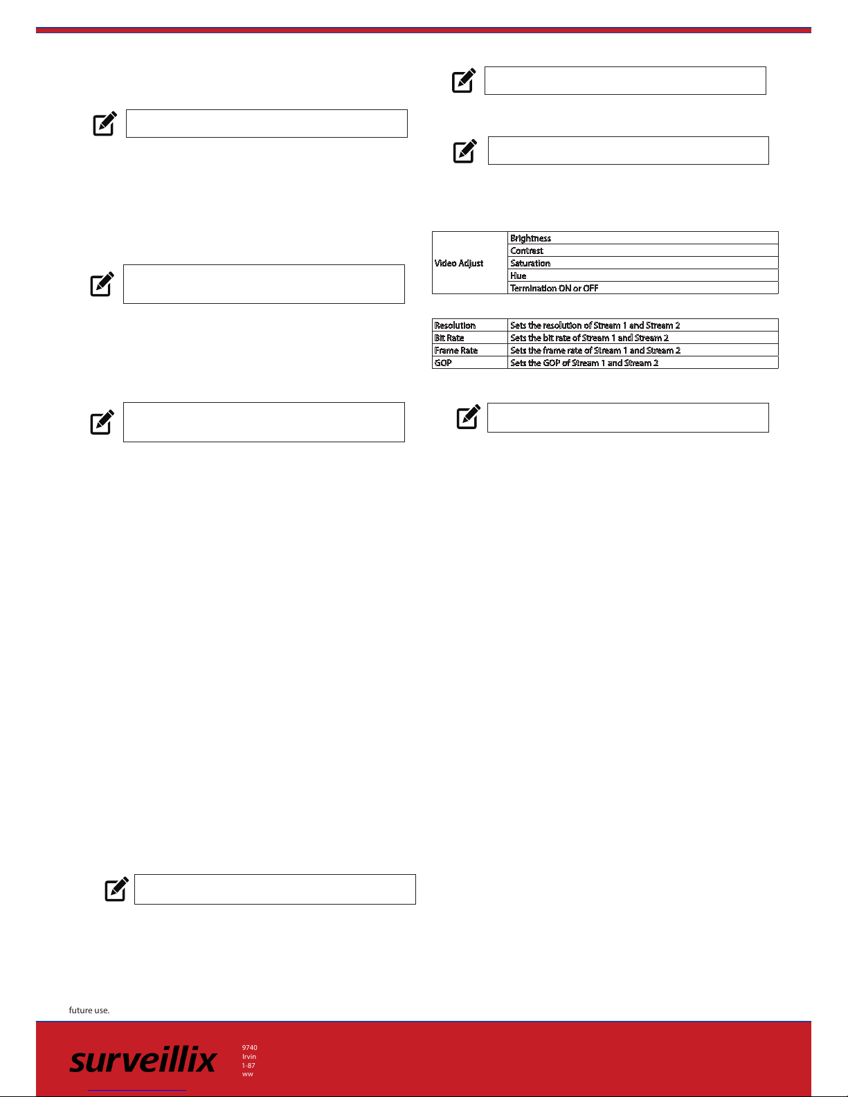
Resolution Sets the resolution of Stream 1 and Stream 2
Bit Rate Sets the bit rate of Stream 1 and Stream 2
Frame Rate Sets the frame rate of Stream 1 and Stream 2
GOP Sets the GOP of Stream 1 and Stream 2
Stream Settings
Video Adjust
Brightness
Contrast
Saturation
Hue
Termination ON or OFF
Camera Setup
Picture Settings
Date / Time Settings
1. Click Encoder Setup.
2. Select the appropriate Time Zone, and then select the desired
date format.
3. Select a method of date and time sync.
4. Click Save to apply the changes.
• Sync with NTP Server - use a specied NTP server and
update interval for the date and time.
• Sync with computer time - use the PC date and time.
• Manual - manually enter the date and time.
NOTE Sync with NTP Server is the recommended Date /
Time setting. The NTP server address is pool.ntp.org.
NOTE The encoder and the PC you use to access the encoder
must be on the same network.
1. Click Encoder Setup.
2. In the Monitor Resolution tab, select a resolution.
3. Click Yes to accept the resolution change and restart the Encoder.
Monitor Resolution
NOTE HDMI spot-out resolution options include 1024 x 768,
1280 x 1024, 720p, and 1080p.
NOTE The Monitor Resolution section applies to spot-out
only.
RS-485 and PTZ Control are currently not available. These features are reserved for
future use.
1. Click Encoder Setup, and then click Alarm Application.
2. Select the desired channel, and then select an alarm setting.
• O - the alarm is not active.
• Normally Open- the alarm will be activated when the circuit is
closed.
• Normally Closed - the alarm will be activated when the circuit
is opened.
3. Select the Triggered Action.
Alarm Application

This manual suits for next models

1

Popular Media Converter manuals by other brands

Black Box LE1510A-R2 Specifications

Black Box

Black Box LE1510A-R2 Specifications

GM International D1072S instruction manual

GM International

GM International D1072S instruction manual

Ntron 1002MC-LX-YY User manual & installation guide

Ntron

Ntron 1002MC-LX-YY User manual & installation guide

SMART-AVI SaviStreamer E300 quick start guide

SMART-AVI

SMART-AVI SaviStreamer E300 quick start guide

Delta PMC-12V100W1AA instruction manual

Delta

Delta PMC-12V100W1AA instruction manual

USR IOT USR-TCP232-ED2 manual

USR IOT

USR IOT USR-TCP232-ED2 manual

Planet VC-201A user manual

Planet

Planet VC-201A user manual

Delta VFD-L Series instruction sheet

Delta

Delta VFD-L Series instruction sheet

Atlas IED TSD-TXHL owner's manual

Atlas IED

Atlas IED TSD-TXHL owner's manual

SMART-AVI V2V-SC4KUHD quick start guide

SMART-AVI

SMART-AVI V2V-SC4KUHD quick start guide

Tripp Lite P137-06N-HDV4K6 quick start guide

Tripp Lite

Tripp Lite P137-06N-HDV4K6 quick start guide

KEPCO SC-FI Series user guide

KEPCO

KEPCO SC-FI Series user guide

Planet VC-231GP user manual

Planet

Planet VC-231GP user manual

Black Box VSP-HDMI1X8-4K user manual

Black Box

Black Box VSP-HDMI1X8-4K user manual

SMART-AVI UUX-PLUS quick start guide

SMART-AVI

SMART-AVI UUX-PLUS quick start guide

Evo-lite Splitter 4 user manual

Evo-lite

Evo-lite Splitter 4 user manual

Data Video NVD-30 instruction manual

Data Video

Data Video NVD-30 instruction manual

BZB Gear BG-HDMI4K-SC user manual

BZB Gear

BZB Gear BG-HDMI4K-SC user manual

manuals.online logo
manuals.online logoBrands
  • About & Mission
  • Contact us
  • Privacy Policy
  • Terms and Conditions

Copyright 2025 Manuals.Online. All Rights Reserved.