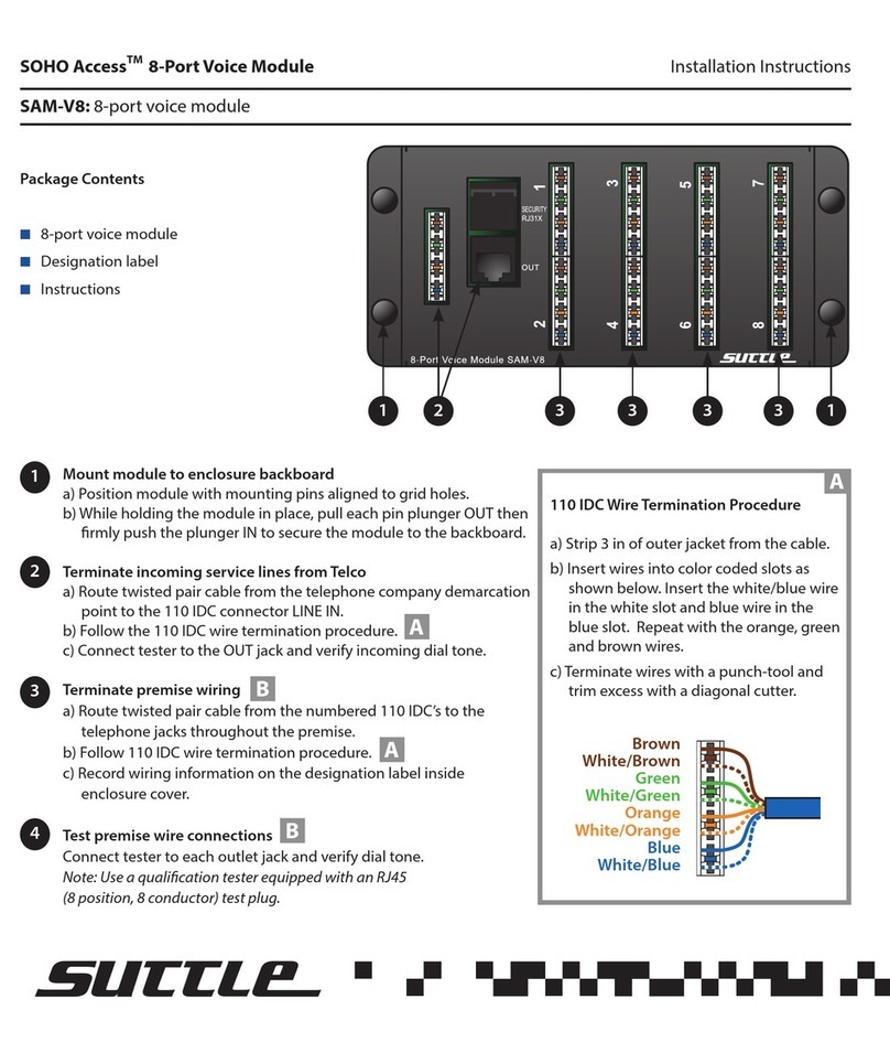
Module Installation
Mounting:
Align the mounting pins with the grid holes on the back of the enclosure.
With the mounting pin plungers in the “out” position, press the unit into
the grid in the desired location, secure by pushing the plungers in.
s on the back of the enclosure.
With the mounting pin plungers in the “out” position, press the unit into
the grid in the desired location, secure by pushing the plungers in.
Terminate incoming service line:Terminate incoming service line:
Run jumper cords to the Module to connect to jacks marked “LINE IN”.
These are RJ-14, 6-position/4-conductor jacks, the inner conductor pair
is Line 1 (3, 5 or 7) and the outer conductor pair is Line 2 (4, 6 or 8).
Run jumper cords to the Module to connect to jacks marked “LINE IN”.
These are RJ-14, 6-position/4-conductor jacks, the inner conductor pair
is Line 1 (3, 5 or 7) and the outer conductor pair is Line 2 (4, 6 or 8).
Out Line 1
ti
Out Line 1
rin
Out Line 1&2
Test Line 1&2
In Line 1&2
Terminate outgoing lines:Terminate outgoing lines:
Run jumper cords from the jacks marked “LINE OUT” to the desired
location, or use the 110 IDC terminals to terminate the outgoing lines.
Run jumper cords from the jacks marked “LINE OUT” to the desired
location, or use the 110 IDC terminals to terminate the outgoing lines.
110 IDC Termination Procedure110 IDC Termination Procedure
Run twisted pair cable from the terminals to the desired location.
Strip 3 in. of outer jacket from the cable. Punch individual cable pairs
down on the 110 IDC. Starting at the blue position on the IDC, begin
with the white wire of each pair as you progress to the orange position
on the IDC as shown below. Press wires into slots with a 110-punch
tool. Trim and discard excess wires.


