Svantek SV 34B User manual

USER MANUAL
SV 34B
ACOUSTIC CALIBRATOR
Warsaw, 2019-03-20
Rev. 1.01
Copyright © 2019 SVANTEK.
All rights reserved.

2
SV 34B User Manual
Contents
1. Introduction...........................................................................................................3
1.1. Calibration ..................................................................................................... 3
1.2. Accuracy of calibration .................................................................................. 3
2. Acoustic calibrator SV 34B...................................................................................5
2.1. General description ....................................................................................... 5
2.2. Using the calibrator........................................................................................ 6
2.2.1. Button functions...................................................................................... 6
2.2.2. Indicators ................................................................................................ 7
2.3. Replacing the batteries.................................................................................. 7
3. SV 34B Technical specifications...........................................................................9

3
SV 34B User Manual
1. INTRODUCTION
1.1. Calibration
Calibrationdetermines theratiobetweenthe input signal valueand the indication onthe display
of the measuring device (or measured result).
In principle, there are more or less large systematic deviations between the displayed
measured value and the true value of the measured signal for every measuring device. The
task of calibration is to determine these systematic deviations.
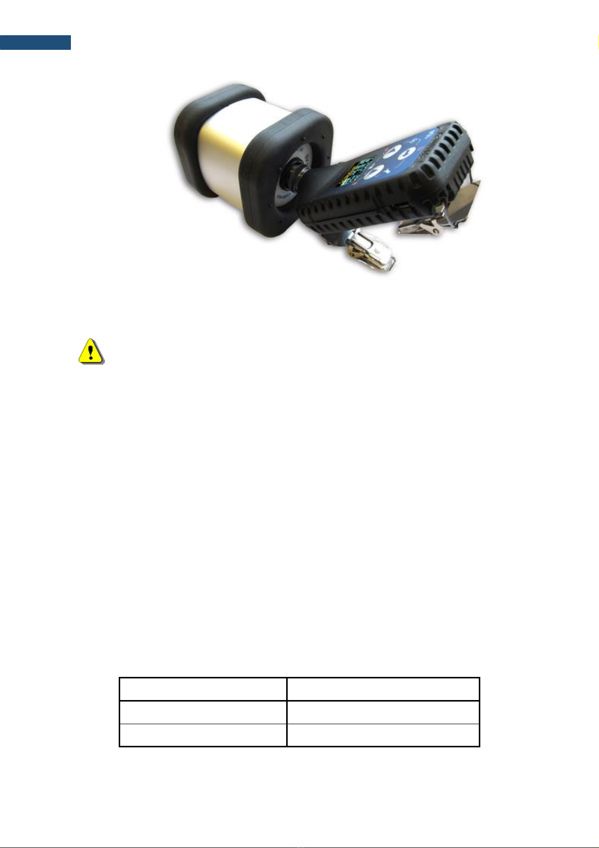
The simplest way to consider such systematic deviations is a correction of measurements by
calibration factor obtained with the use of an acoustic calibrator.
However, in many cases it is sufficient to determine that the systematic deviations are within
certain limits.
"Correct" value of the measured signal is set before calibration, and this value is compared
with a value measured by the measuring device.
Thus, calibration means establishing a relationshipbetween the reference and measured value
of the variable for the corresponding standard to be able to take this ratio into account in
subsequent measurements as a correction factor (calibration factor).
1.2. Accuracy of calibration
Measuring equipment and measurement methods have deviations. The measured variable is
affected by environmental conditions (temperature and humidity), as well as the operator's
actions. The displayed value of the measured variable will therefore usually deviate from the
true value of the measured variable.
It is recommended to check the SV 34B every 2 years with periodic testing of the test
equipment to ensure that the level values do not change, and the test results are reliable.
It is important to carefully check who should perform such monitoring:
- internally by the monitoring body,
- SVANTEK's own calibration laboratory according to ILAC,
- externally from PTB = Physikalisch-Technische Bundesanstalt or
- another local accredited laboratory.
Accuracy
There is a deviation between the true value and the average value of the series of
measurements under repetitive conditions, which is the result of repeated measurement of the
reference level.
Overview of the classification of sound level meters and calibrators
Classification of sound level meters and acoustic calibrators
The acoustic calibrators (see IEC 60942. 2003) and the sound level meters (see IEC 61672:
2002) are classified into their respective classes and types for accuracy.

4
SV 34B User Manual
Type LS is subject to the strictest requirements of the device. Devices of this class are
classified as the most precise.
Each of the following types (LS, 1 and 2) allow a wider tolerance range (see Table 1).
Table 1. Tolerances for these types of acoustic devices, except for the maximum extended
measurement uncertainty (f = 1kHz)
Class / Type
LS
1
2
Sound level meters (dB)
-
0.7
1.0
Acoustic calibrators (dB)
0.10
0.25
0.40
As shown in Table 1, the acoustic calibrator has unambiguously lower tolerances than the
sound level meter of the same class. Thus, the calibrator, as a reference of acoustic pressure,
should be more precise than a sound level meter.
With respect to acoustic measurements conducted in accordance with the standard, the
requirements for calibrating the measuring channel before each measurement and very often
also after measurement are mandatory.

5
SV 34B User Manual
2. ACOUSTIC CALIBRATOR SV 34B
2.1. General description
The SV 34B acoustic calibrator is a small, portable one-range Class 2 device (sound source),
see Picture 1. The SV 34B is suitable for calibration of Class 2 sound level meters and
dosimeters with ½” microphones. Powered by two LR03/AAA batteries, it contains a
loudspeaker producing acoustic pressure, reference piezoresistive sensor for monitoring
generated level, pressure and temperature sensors for measurements of atmospheric
conditions and a microprocessor system controlling the operation of the calibrator. A sinusoidal
waveform of 1 kHz frequency is digitally generated and feeds the loudspeaker. The sampled
signal from the reference piezoresistive sensor indicates the level of currently generated signal
in a feedback loop. Based on the information about the level of the signal, actual values of
pressure and temperature, microprocessor adjusts amplification of the loudspeaker signal in
order to produce appropriate sound pressure level in the calibrator’s chamber.
Note: Due to the feedback regulation loop the SV 34B calibrator does not require
user’s adjusting and operates in a wide range of temperatures and humidity (see
SV 34B Datasheet).
Picture 1. Acoustic calibrator SV 34B
The SV 34B is designed for calibration of sound level meters with ½” microphones. Picture 2
shows the way of insertion of a ½” microphone into the calibrator.

6
SV 34B User Manual
Picture 2. Calibration of the personal exposure meter with a ½” measurement microphone
Note: For calibration of a meter with a ¼” microphone the SA 30 reduction adapter
must be applied.
2.2. Using the calibrator
2.2.1. Button functions
The SV 34B calibrator is equipped with a button for controlling operation of the device. The
button is used to turn the device ON and OFF. In this case the button pushing has immediate
effect.
When the SV 34B is either ON or OFF pressing the button over 10 seconds and releasing it
will cause full reset of the system. Normally this function is not necessary. It has been
implemented in the case of inappropriate operation of the calibrator caused by external (EM
radiation, subnormal atmospheric conditions, etc) or internal (inappropriate system reset as a
result of battery replacement, etc) factors.
The operation time of the calibrator with a microphone put inside its chamber is limited to 3-5
minutes. This functionality was added in order to save the battery life, e.g. when the calibrator
is accidentally left with the microphone inside.
Table 2. Functional description of the calibrator’s button.
Button press
Function description
Short, less than 10 sec.
Turn the device on/off
Long, over 10 sec.
Full reset of the system

7
SV 34B User Manual
2.2.2. Indicators
There aretwo LEDs to indicatethe stateof the SV 34Bcalibrator. One of them is titled “114 dB”
and shows the condition of the generated level.
After the calibrator is put on the microphone and switched on, acoustic pressure inside the
calibrator’s chamber is automatically adjusted to the desired level. During that process
“114 dB” diode blinks with a frequency of approx. 2 Hz.
The device is ready when this diode is on with a continuous light.
Note: Calibration should not be performed until the “114 dB” diode light is
continuous.
The diode called “LOW BAT.” presents the batteries status. When the combined battery
voltage is less than 2.1 V the “LOW BAT.” diode will blink with a frequency of approximately
2 Hz. It is recommended to not use the SV 34B calibrator in this state as the generated level
may differ from the declared values.
Note: Replace both batteries, when when the diode “LOW BAT.” blinks.
Picture 4. The top view of the SV 34B calibrator with one diode on
2.3. Replacing the batteries
The batteries should be replaced as follows:
a) remove the rubber cover on the button and diodes’ side

8
SV 34B User Manual
b) holding the cover unscrew four fixing screws with your
fingers
c) take off the cover and remove discharged batteries
d) put two new batteries in
place of the discharged
ones with polarization as
indicated on the printed
board and calibrator’s case
e) carefully put on the cover so that the diodes fit the
corresponding holes in it
f) holding the cover with one gently hand fasten the fixing
screws
g) put on the rubber cover.

9
SV 34B User Manual
3. SV 34B TECHNICAL SPECIFICATIONS
Output signal
Sound Pressure Level (SPL): 114 dB, with respect to 20 Pa in reference conditions
Output frequency 1000 Hz
Accuracy: IEC 60942: 2003 standard, Class 1
SPL Accuracy: 0.5 dB
Frequency accuracy: 0.02 %
Total Harmonic Distortion (THD) < 0.75 %
Reference conditions
Temperature: 23 C
Atmospheric pressure: 101.3 kPa
Humidity: 30-80% RH
Effective microphone load volume: 250 mm3, microphone type: Brüel&Kjaer 4134, SN:1591010
General data
Effective load volume sensitivity: 0.00027 dB/mm3
Level stabilization time: typical 7 sec., max. 10 sec.
Microphone dimensions: ½” (13.2 mm) or ¼” with reduction adapter SA 30
Storage temperature range: -25 C to +70 C (-13 F to +158 F)
CE classification: EN 61010-1: 2010, EN 61326-1:2013, EN 60942:2003
Working conditions
Temperature range: from 0C to +40C (32 F to 104 F)
Atmospheric pressure range: from 65 kPa to 108 kPa (19.2 inHg to 31.9 inHg)
Humidity range: from 25% to 90% RH
Environmental conditions influence (typical)
Temperature coefficient: 5·10-3 dB/C
Pressure coefficient: 1·10-4 dB/hPa
Humidity coefficient: 1.25·10-3 dB/%
Power supply
Battery type: two LR03 (IEC)/AAA (ANSI) alkaline batteries
Continuous operation time: 30 hours
Standby mode: approx. 2 years
Minimal operating voltage: 2.1 V DC
Dimensions and weight
Weight: 305 g (10.9 oz) with batteries
Dimensions: 65 x 65 x 70 mm

10
SV 34B User Manual
EMC properties
•The configuration with the highest RF emission in the direction parallel to the axis of the
calibrated microphone in the acoustic chamber
•The lowest level of noise immunity is parallel to the axis of the calibrated microphone in
the acoustic chamber.
Other connections with the calibrator are not available.
Table of contents
Other Svantek Test Equipment manuals