2. Calibration
One of the fundamental questions, that are most frequently asked while taking a
measurement, is whether its result is accurate. Proceeding, with a measurement without
having a positive answer to this question, may result in obtaining data of no practical use
and wasting our time. However, we may easily obtain the answer by performing a calibration
of the vibration level meter using a vibration calibrator. This device should be used before
every set of measurements.
The vibration calibrator is a device, which produces the vibration of the defined levels and
frequency. It allows to calibrate the vibration meter in comparative way.
Calibration procedure is also the best way for the complete measuring system (Meter, Cable
and Transducer connected together) check. This is an essential action for the reliable
measurements performed in the field!
3. Accuracy of calibration
Each measurement performed by any measurement device is burdened with an error. Result
obtained from such measurement is only an estimate of the real value of the measured
quantity. Hence, the purpose of calibration is to limit this inevitable error to a certain
acceptable level. Maximum absolute value of the error of generated vibration signals is
called the tolerance and is strictly defined by the standard ISO8041:2005.
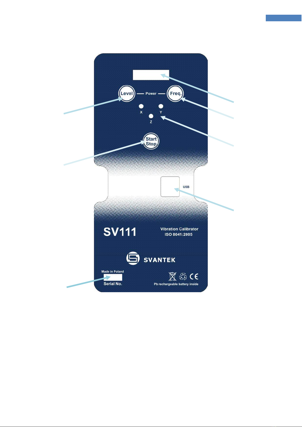
4. SV111 model information
The model SV111 is a Portable Vibration Calibrator. It is designed to check/calibrate various
types of vibration level meters according to the ISO 8041:2005.
Three standard frequencies 15.92 Hz, 79.58 and 159.2 Hz (plus one more extra 636,6Hz)
combined with high loading mass brings opportunity to calibrate almost any existing
transducer.
Because of its dedicated adapters, SV111 allows to take measurements in three directions.
So, to calibrate effectively tri-axial transducers!
Because of its own internal rechargeable battery, it is a truly mobile and flexible device
designed to use either in a laboratory or during fieldwork.
The unique feature of SV111 is capability to calibrate complete “seat accelerometer”,
without necessity to extract accelerometer form the rubber cushion!
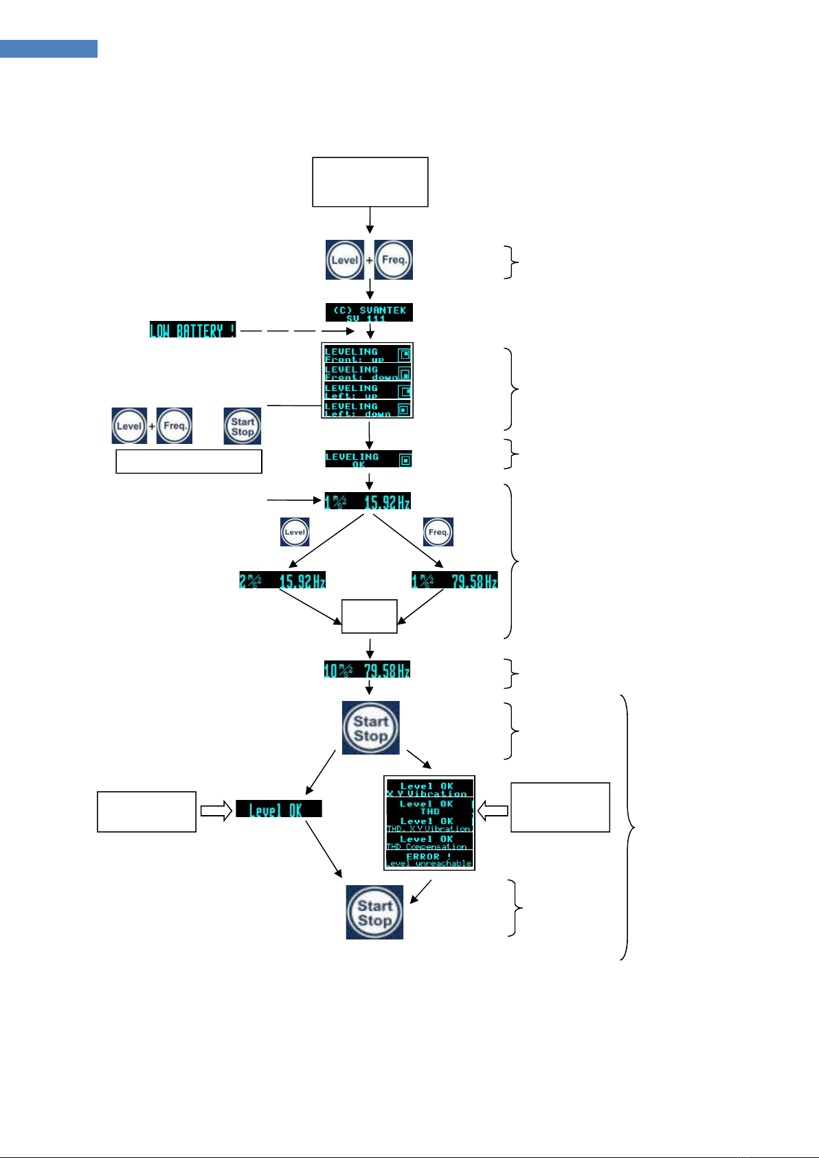
The robust case allows placing the calibrator directly on the ground, what is extremely useful
in the field applications. Built in electronic leveling system helps with correct positioning of
the device for correct vibration calibration. Leveling of the SV111 is important for keeping
transversal vibrations levels within tolerances specified by the ISO8041:2005.