SVC GROUP WEDI-4 User manual

Wireless External Data
Interface (WEDI-4)
P/N: ASM1024-600
SER MAN AL
Revision 1.0
29 Firemens Way, Poughkeepsie, New York 12603 SA
Voice: (845) 471-7007, Fax: (845) 471-7020, E-mail: [email protected]
Copyright
2019 Spectra Vista Corporation


SVC WIRELESS EXTERNAL DATA INTERFACE 4 CHANNEL USER MANUAL REVISION 1.0
Table Of Contents
INTROD CTION .................................................................................................................................. 1
FOR BEST RESULTS, THE WEDI-4 MAY BE MOUNTED ON A TRIPOD USING ITS BUILT-IN ¼-20
BOTTOM MOUNT, AS SHOWN BELOW............................................................................................... 3
CONTROLS AND INDICATORS ........................................................................................................ 4
P
OWER
S
WITCH
.................................................................................................................................................................... 4
LED/A
UDIO
B
EEPER
......................................................................................................................................................... 4
PAIRING WEDI-4 WITH YO R INSTR MENT .............................................................................. 5
WEDI-4 SAGE – STAND-ALONE MODE ........................................................................................ 7
WEDI-4 SAGE – PC MODE................................................................................................................ 9
WEDI-4 RECHARGEABLE BATTERY .............................................................................................. 12
C
HARGING
T
HE
B
ATTERY
............................................................................................................................................... 12
C
HECKING
B
ATTERY
OLTAGE
..................................................................................................................................... 13
R
EPLACING THE
B
ATTERY
............................................................................................................................................... 15
CONFIG RATION OPTIONS ........................................................................................................... 18
SPECIFICATIONS ............................................................................................................................... 19
APPENDIX A – HARDWARE DESCRIPTION ..................................................................................20

SVC WIRELESS EXTERNAL DATA INTERFACE 4 CHANNEL USER MANUAL REVISION 1.0
Table Of Figures
Figure 1 WEDI-4 Top iew Showing Built-In PAR Sensor ........................................................................................... 1
Figure 2 WEDI-4 Side iew Showing External Sensor Inputs – Pyranometer (SPN-1), and Thermistor (T) ....... 1
Figure 3 Using The WEDI-4 In The Field With arious Sensors .................................................................................. 2
Figure 4 i-Series External Data Bluetooth Antenna Location ......................................................................................... 3
Figure 5 WEDI-4 Mounted Securely To A Tripod ........................................................................................................... 3
Figure 6 WEDI-4 Power Switch ........................................................................................................................................... 4
Figure 7 WEDI-4 Unique Bluetooth Address Tag, Chassis Bottom .............................................................................. 5
Figure 8 PC Software Pairing ................................................................................................................................................. 5
Figure 9 LCD Pairing Process, Before Turning On The WEDI-4 ................................................................................. 6
Figure 10 LCD Pairing Process, Completed ....................................................................................................................... 6
Figure 11 Waiting for the Initial Reference Scan ............................................................................................................... 7
Figure 12 LCD Indicating Downwelling Radiance Is Currently Down 3 Percent vs Reference ............................... 8
Figure 13 LCD Indicating Downwelling Radiance Is Currently Up 10 Percent vs Reference .................................. 8
Figure 14 PC Software WEDI Controls Example ............................................................................................................. 9
Figure 15 PC Software New Main Screen Buttons and External Data Display Fields ............................................. 10
Figure 16 External Data Display After Reference Scan .................................................................................................. 11
Figure 17 External Data Display After Ext Data Scan ................................................................................................... 11
Figure 18 External Data Display After Target Scan - Cloud Cover! ............................................................................ 11
Figure 19 WEDI-4 Battery Charging Port ........................................................................................................................ 12
Figure 20 WEDI-4 Battery Charger ................................................................................................................................... 12
Figure 21 WEDI-4 Battery oltage Displayed On Channel 5 ....................................................................................... 13
Figure 22 Battery oltage Measurement - Across SPN-1 Connector Pins 2 and 3 ................................................... 14
Figure 23 Battery Replacement – Opening The Unit ...................................................................................................... 15
Figure 24 Battery Replacement - Connector J2 "BATT" Partially Removed ............................................................. 16
Figure 25 Battery Replacement - Old Battery Prepared For Removal ......................................................................... 16
Figure 26 WEDI-4 Battery With Foam Tape Applied .................................................................................................... 17

1
11
1
SVC WIRELESS EXTERNAL DATA INTERFACE 4 CHANNEL USER MANUAL REVISION 1.0
Introduction
The S C 4 channel Wireless External Data Interface (WEDI-4) is a companion product to the
Spectra ista i-Series of spectroradiometers. The WEDI-4 provides a platform to wirelessly inject
data from the built-in Li-Cor PAR sensor, as well as data from external sensors, into the scan data
acquired by the spectroradiometer.
Figure 1 WEDI-4 Top iew Showing Built-In PAR Sensor
Figure 2 WEDI-4 Side iew Showing External Sensor Inputs – Pyranometer (SPN-1), and Thermistor (T)
The WEDI-4 provides a cost effective method to monitor and record data from sensors, while
acquiring high-quality spectral data with the S C i-Series spectroradiometers. The i-Series
2
22
2
SVC WIRELESS EXTERNAL DATA INTERFACE 4 CHANNEL USER MANUAL REVISION 1.0
spectroradiometers incorporate a second Bluetooth radio, which can receive data from sensors
connected to the WEDI-4.
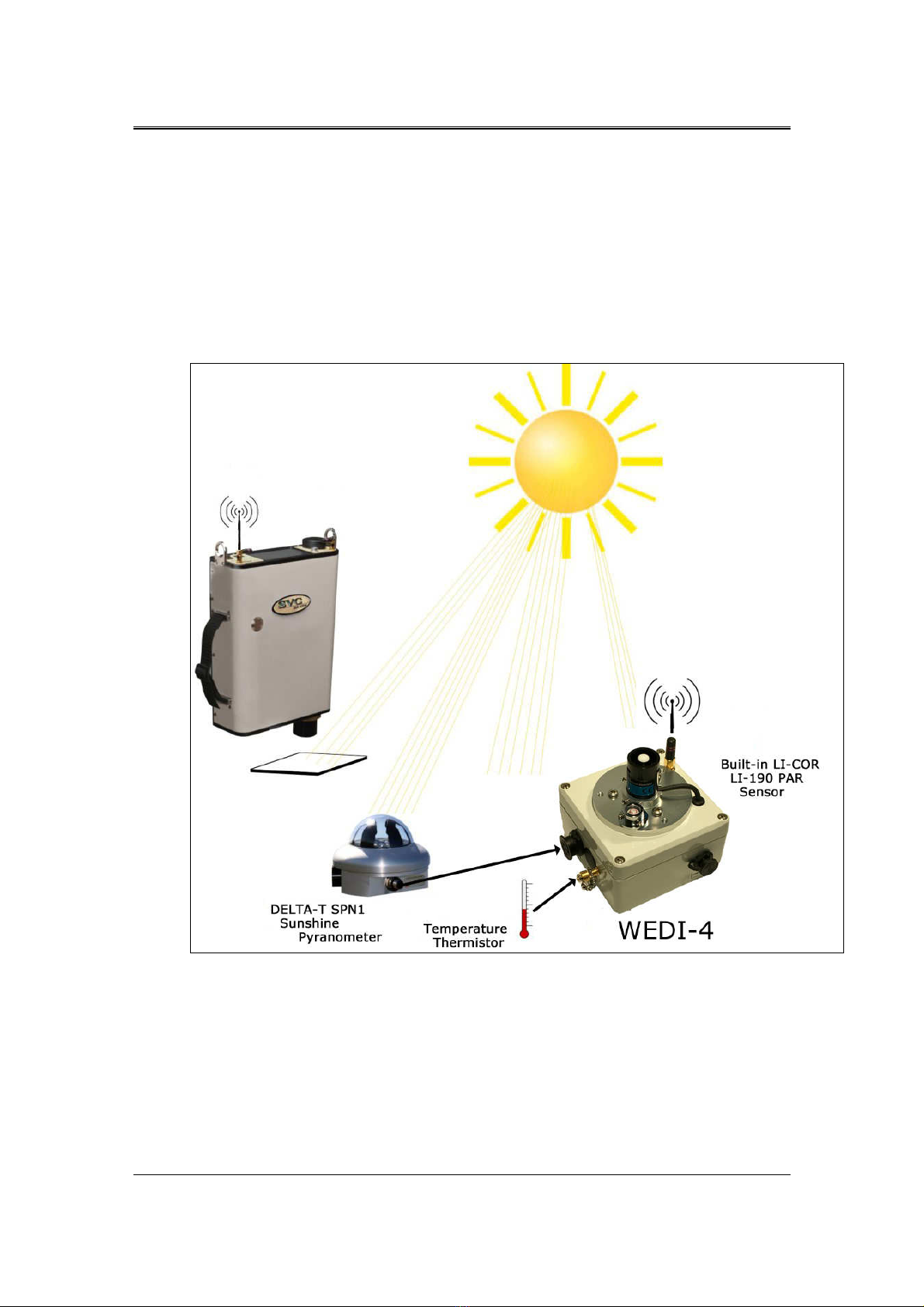
The external sensors and WEDI-4 can be placed near the area of interest as the spectroradiometer is
moved from target to target. By using just the PAR Sensor (supplied with the WEDI-4) the
instrument operator can be alerted to changes in downwelling irradiance and take action to avoid
collecting erroneous data. The i-Series instruments record the external sensor data for each
measurement.
The i-Series spectroradiometer operator is immediately aware of changes to downwelling sensor
signal, and can take the appropriate action.
Figure 3 Using The WEDI-4 In The Field With arious Sensors
Note that the antenna located on the upper right side of i-Series rear panel is the one used to
communicate with the WEDI-4. When not in use, it is recommended that the External Data
Bluetooth Antenna be removed and replaced with the cap furnished with the instrument.

3
33
3
SVC WIRELESS EXTERNAL DATA INTERFACE 4 CHANNEL USER MANUAL REVISION 1.0
Figure 4 i-Series External Data Bluetooth Antenna Location
For best results, the WEDI-4 may be mounted on a tripod using its built-in ¼-20 bottom mount, as
shown below.
Figure 5 WEDI-4 Mounted Securely To A Tripod
4
44
4
SVC WIRELESS EXTERNAL DATA INTERFACE 4 CHANNEL USER MANUAL REVISION 1.0
Controls And Indicators
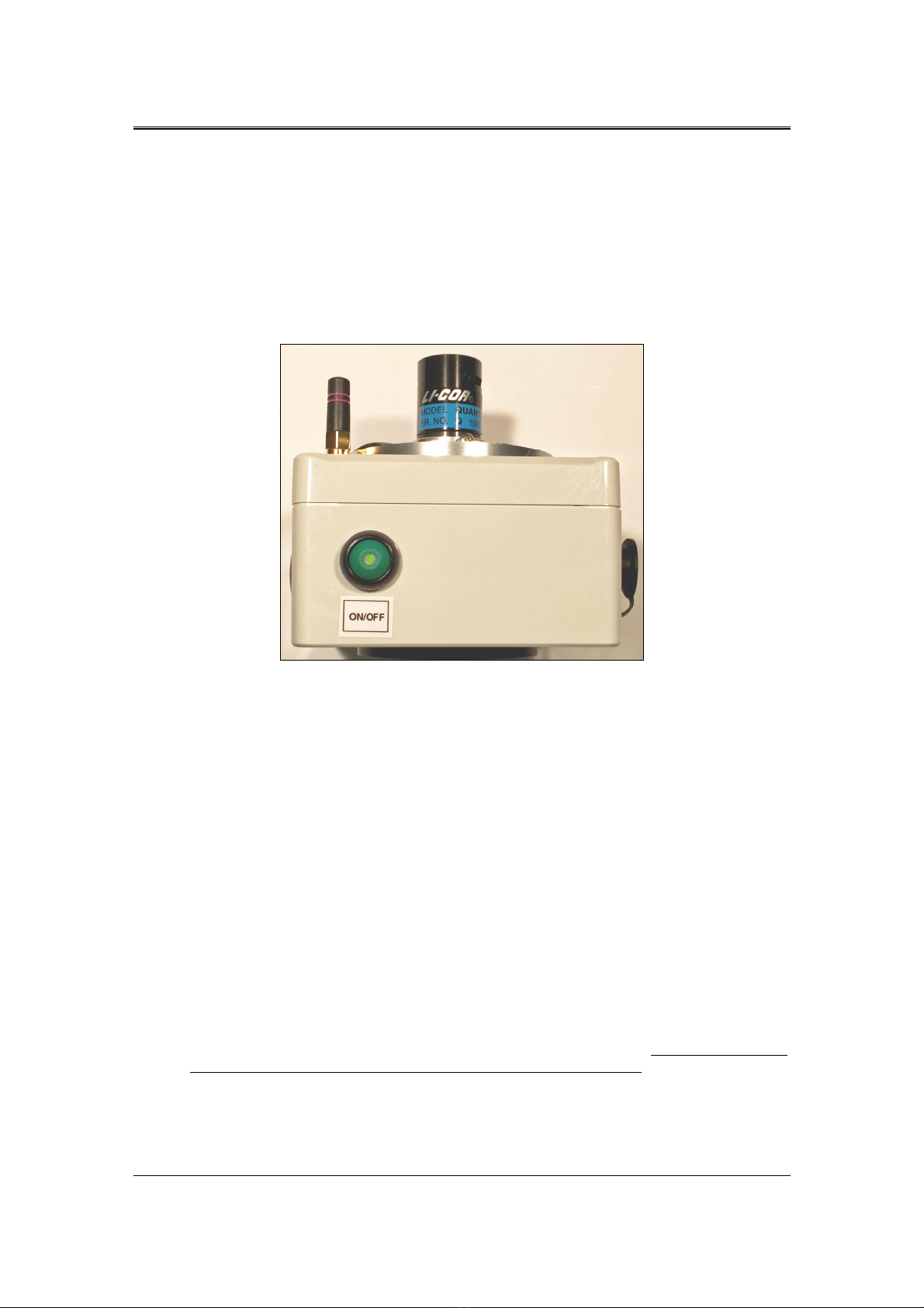
Power Switch
The power switch is of type push-on / push-off, with an LED indicator mounted in the center of the
round power switch push button.
Firmly press the power switch once to turn power on, and press again to turn power off.
Figure 6 WEDI-4 Power Switch
LED/Audio Beeper
The WEDI-4 uses an internal audio beeper and power switch mounted LED to indicate the following
conditions:
At power-up:
The unit emits a single 1 second beep to indicate that power has been applied, and that the firmware
has successfully started. The LED lights and stays on solid to indicate sufficient battery voltage to run
the device.
When the Bluetooth radio connection with the paired i-Series instrument has failed:
The unit emits a 1 second beep every 10 seconds until the connection to the instrument has been
restored.
When the battery voltage is low:
The unit emits a 0.5 second beep every 2 seconds, and flashes the power switch LED. When this
occurs, the WEDI-4 should be turned off until it the battery can be recharged. Failure to turn off the
unit under low-battery conditions will reduce the lifetime of the battery.

5
55
5
SVC WIRELESS EXTERNAL DATA INTERFACE 4 CHANNEL USER MANUAL REVISION 1.0
Pairing WEDI-4 With Your Instrument
The WEDI-4 uses a Bluetooth radio to wirelessly send sensor data to the i-Series instrument. Prior to
using the WEDI-4, this Bluetooth radio must be paired with a specific i-Series instrument. This
pairing process only needs to be performed once, as the i-Series instrument remembers the paired
device across power cycles.
Each WEDI-4 has a unique 12 character hexadecimal Bluetooth address. This unique address appears
on a tag located on the bottom of each WEDI-4 chassis, as shown below:
Figure 7 WEDI-4 Unique Bluetooth Address Tag, Chassis Bottom
The pairing process uses the i-Series PC Data Acquisition Software to configure the WEDI-4
Bluetooth address into the i-Series instrument.
Once the PC Data Acquisition Software is started and connected to the i-Series instrument, use the
software’s “Control->Setup External Data…” dialog to begin the pairing process (shown below).
Set the “External Data Source” field and “Bluetooth Address” field according to your model
instrument and your unique WEDI-4 Bluetooth address, and press the “Update Instrument” button
to send the address to the instrument.
Figure 8 PC Software Pairing
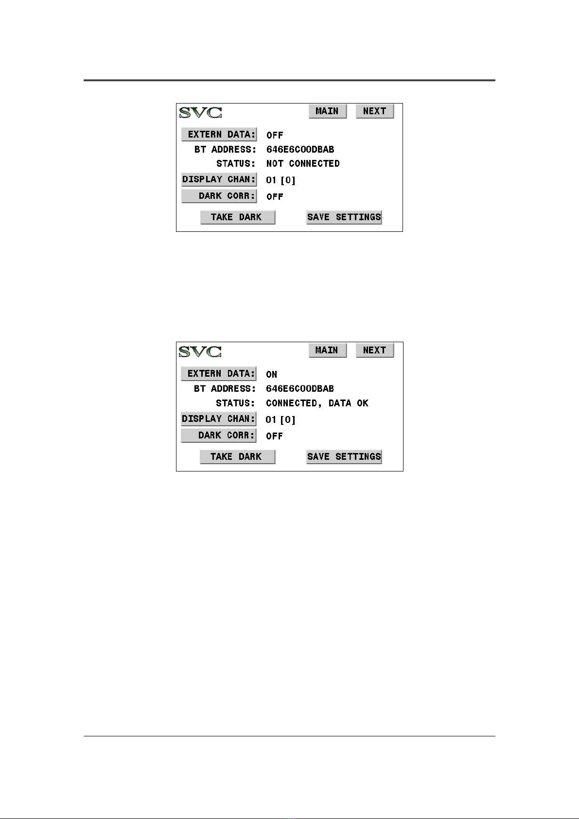
Over on the i-Series instrument LCD (setup screen #4, EXTERN DATA), the Bluetooth Address
should now match the one just sent from the PC software. See below:
6
66
6
SVC WIRELESS EXTERNAL DATA INTERFACE 4 CHANNEL USER MANUAL REVISION 1.0
Figure 9 LCD Pairing Process, Before Turning On The WEDI-4
To complete the pairing process:
•Press the “EXTERN DATA:” button on the LCD to changes its state to “ON”.
•Press the power switch on the WEDI-4 to turn the unit ON.
Once turned on and connected, the instrument’s LCD screen should change its “STATUS:” field to
“CONNECTED, DATA OK” as shown below: This indicates a successful pairing, with data
streaming from the WEDI-4 to the i-Series instrument.
Figure 10 LCD Pairing Process, Completed
Once the pairing is complete, press the “SA E SETTINGS” button. This will cause the i-Series
instrument to automatically attempt to re-connect to the WEDI-4 every time the instrument is
powered up. It will also automatically select channel 1 as the current display channel.
If the LCD shows any other STATUS after the above steps, then check:
•That the Bluetooth Address as found on the bottom of the WEDI-4 chassis was entered
correctly.
•Check/charge the WEDI-4 battery; it may be low.
•Ensure that the External Data BT Antenna, located to the right of the instrument’s LCD
display, has been installed.

7
77
7
SVC WIRELESS EXTERNAL DATA INTERFACE 4 CHANNEL USER MANUAL REVISION 1.0
WEDI-4 sage – Stand-Alone Mode
In stand-alone mode, the instrument’s main LCD screen displays the relative amplitude of the
currently selected WEDI-4 display channel (“DISPLAY CHAN:” in the external data setup screen)
with respect to its amplitude at the time of the last reference scan. In this way, the instrument operator
is always aware of whether the downwelling radiance (for example) has changed since the last
reference was taken.
The main LCD screen has an area labeled “EXT” that, once an initial reference scan has been
acquired, displays the percentage change in any WEDI-4 channel since the time of the last reference.
Prior to the initial reference scan, the “EXT” field displays the string “REF”, indicating that no initial
reference scan has been acquired yet. So the instrument is waiting for the initial reference. See below:
Figure 11 Waiting for the Initial Reference Scan
Note that the “EXT” field will also display “OFF” if the “EXTERN DATA” field mentioned earlier
in the setup screen has been set to “OFF”. In addition, the “EXT” field will display “N/C” if no
connection exists between the instrument and the WEDI-4.
After the initial reference scan, the “EXT” field will display a constantly updating percentage-change
value for the selected “DISPLAY CHAN”.
For example, the Li-Cor LI-190 PAR sensor is built-in to the WEDI-4. This sensor corresponds to
display channel 1 (see Appendix A for a complete mapping from WEDI-4 inputs to display channels).
In this example, with the LCD setup screen “DISP CHAN:” set to channel 1, the “EXT” field on the
main LCD display will track downwelling radiance as a percentage of reference in real time for the
operator.
In this case, the “EXT” value on the screen below shows that the current downwelling radiance is 3%
less than at the time that the reference scan was taken:

8
88
8
SVC WIRELESS EXTERNAL DATA INTERFACE 4 CHANNEL USER MANUAL REVISION 1.0
Figure 12 LCD Indicating Downwelling Radiance Is Currently Down 3 Percent vs Reference
The “EXT” value on the following screen indicates that the current downwelling radiance is 10
percent greater than at the time that the reference scan was taken:
Figure 13 LCD Indicating Downwelling Radiance Is Currently Up 10 Percent vs Reference
When the “EXT” field indicates that the current downwelling conditions have changed too much, then the
target scan should perhaps be delayed (possibly to allow clouds to move from the sun). Alternately, a new
reference scan might be acquired.

9
99
9
SVC WIRELESS EXTERNAL DATA INTERFACE 4 CHANNEL USER MANUAL REVISION 1.0
WEDI-4 sage – PC Mode
In PC data acquisition mode, the i-Series Window PC software is used to acquire scans from the
instrument.
After connecting the software to the i-Series instrument, use the software’s “Control->Setup External
Data…” dialog (shown below) to enable and set up the correct external data channels.
Figure 14 PC Software WEDI Controls Example
In the example above, the WEDI-4 controls are set as follows:
•“External Data Acquisition” has selected only channel 1 (the Li-Cor LI-190 PAR sensor
input; see Appendix A) of the 16 possible channels as containing valid data; this is noted in
any resulting SIG files in the header’s “external data mask=” field. [See the i-Series User
Manual for more details on external data and SIG file header fields for more information].
•“External Data Display” has enabled and selected channel 1 data for display and calculations
on the PC software’s main screen. [See below for more information].
•“Adjust Displayed alues For External Dark Current” is un-checked. Each of the WEDI-4
channels may optionally require dark-current subtraction in order to produce values that are
directly proportional to their corresponding input sensor voltages. In this example, the Li-
Cor PAR sensor does not require dark correction for typical usage.
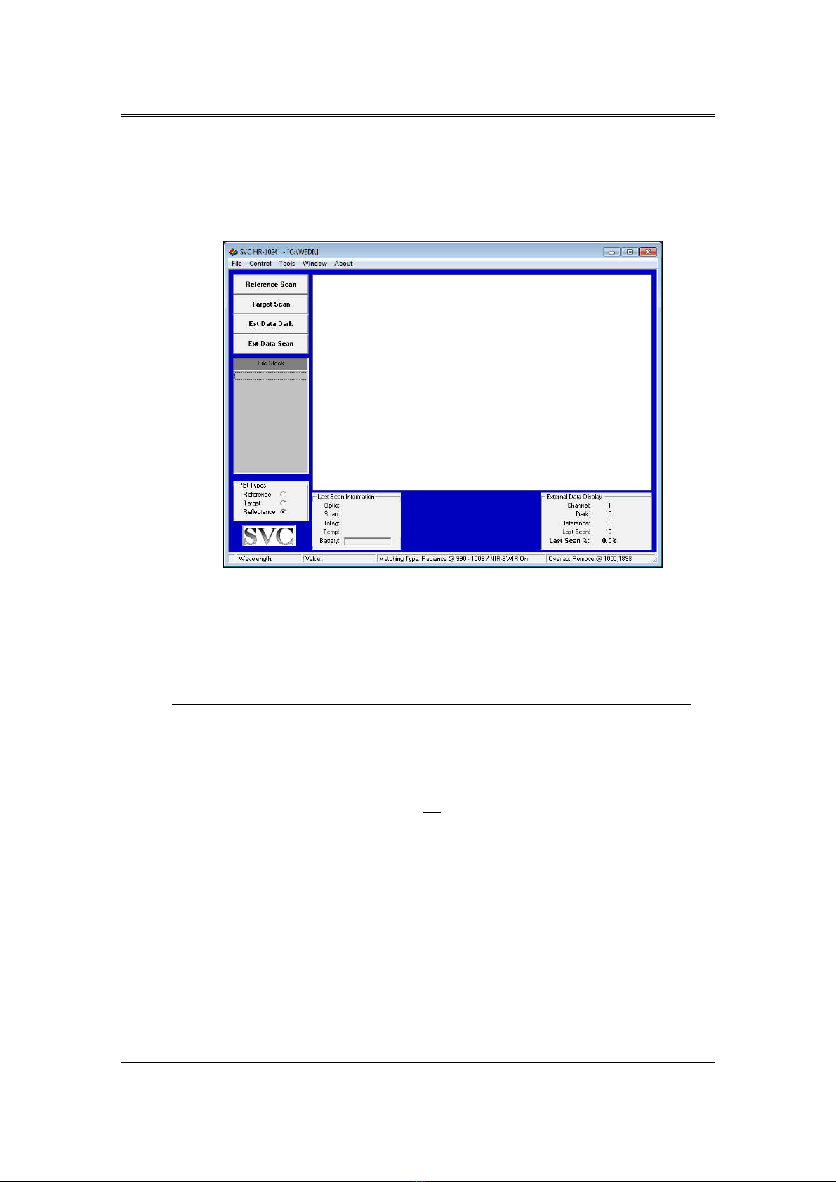
When set up as described above, two new data acquisition buttons now appear on the PC software’s
main screen in the upper-left corner. These buttons are “Ext Data Dark” and “Ext Data Scan”.
1 0
1 01 0
1 0
SVC WIRELESS EXTERNAL DATA INTERFACE 4 CHANNEL USER MANUAL REVISION 1.0
In addition, a new dialog “External Data Display” appears in the PC software’s main screen in the
lower-left corner. This dialog displays external data.
These new external data-related fields are shown below, and are then described in detail in the
following paragraphs:
Figure 15 PC Software New Main Screen Buttons and External Data Display Fields
When the “Ext Data Dark” button is pressed, the PC software acquires and stores a single set of dark
data values from the attached WEDI-4. These dark values will automatically be subtracted from all
future scan data, if the “Adjust Displayed alues For External Dark Current” checkbox mentioned
earlier is checked. Note that it is the operator’s responsibility to ensure that all sensors currently
connected to the WEDI-4 are configured as “dark” at the time that this button is pressed.
The “Ext Data Dark” button need not ever be pressed if the WEDI-4 sensors do not require dark
current correction.
When the “Ext Data Scan” button is pressed, the PC software acquires a single set of data values from
the WEDI-4. If either display channel A or B is selected, the software also displays the selected data in
the “External Data Display” box in the lower right.
Note that pressing either of these buttons does not result in new spectral data acquisition; only new
WEDI-4 sensor data is acquired. The operator must still press either the “Reference Scan” or “Target
Scan” buttons in order to acquire spectral data from the instrument.
For the example usage described below, continue to assume that the Li-Cor PAR sensor is attached to
the WEDI-4 and its data appears on Display Channel 1.
The first step in taking advantage of the WEDI-4 in the field is, as always, to acquire a reference scan.
This is done by pressing the software’s “REFERENCE SCAN” button. In this case, the “External
Data Display” dialog is updated as follows:
1 1
1 11 1
1 1
SVC WIRELESS EXTERNAL DATA INTERFACE 4 CHANNEL USER MANUAL REVISION 1.0
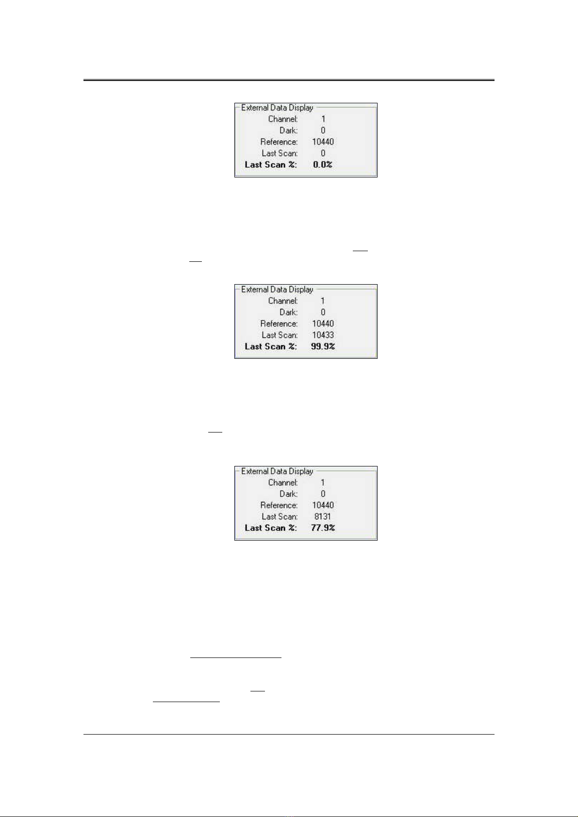
Figure 16 External Data Display After Reference Scan
This shows that the PAR sensor’s downwelling radiance value was 10440 units during the most recent
Reference Scan. The “Last Scan” indicates that we have not yet acquired any WEDI-4 sensor data
associated with a Target Scan since our last Reference Scan.
Now, just prior to acquiring an actual Target Scan, the operator may first press the “Ext Data Scan”
button, in order to test if the current downwelling radiance is still the same as it was during the most
recent Reference Scan. This is shown below:
Figure 17 External Data Display After Ext Data Scan
This shows that the current downwelling radiance (“Last Scan Field”) is 10433 units, or 99.9% when
compared to what it was at the time of the last Reference Scan. So a Target Scan could be quickly
acquired right now - a new Reference Scan is not required.
The “Last Scan” field is also updated whenever the Target Scan button is pressed. This allows the
operator to immediately know when a Target Scan must be discarded, because downwelling radiance
has changed too much. This situation is shown below:
Figure 18 External Data Display After Target Scan - Cloud Cover!
This shows that the target we just acquired had only 8131 downwelling radiance units, or 77.9% when
compared to what it was during the prior Reference. This Target Scan may have to be discarded, since
the absolute reflectance calculation from this target data will be incorrect due to the changed lighting
conditions between the Reference and Target Scan.
In summary:
•The “Ext Data Scan” button immediately updates the “Last Scan %” field, which may be
examined just prior to a target scan, in order to know whether conditions are still suitable for
a new target.
•The “Target Scan” button also updates the “Last Scan %” field, which may be examined
after a target scan to judge whether the target scan contains good spectral data, or should be
discarded.
1 2
1 21 2
1 2
SVC WIRELESS EXTERNAL DATA INTERFACE 4 CHANNEL USER MANUAL REVISION 1.0
WEDI-4 Rechargeable Battery
The WEDI-4 operates from an internal 9.6 NiMH rechargeable battery. It is recommended that the
battery be recharged prior to the start of each day of active data acquisition in the field to ensure a
day’s worth of uninterrupted field work.
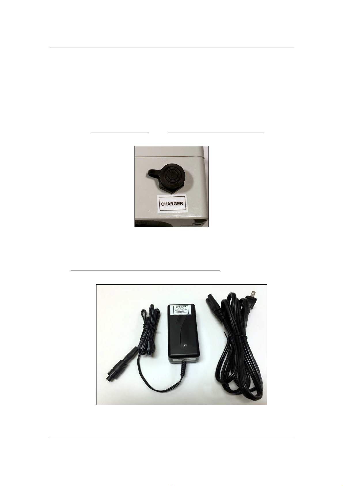
Charging The Battery
With the WEDI-4 power turned off and the battery charger disconnected from the mains, remove the
charging port cap and plug the battery charger into the WEDI-4 charging port.
Figure 19 WEDI-4 Battery Charging Port
Plug the battery charger into the mains. The LED on the charger turns RED while the battery is being
charged, and turns GREEN when the battery is fully charged. It takes approximately 2 hours to fully
charge a depleted battery.
Do not turn on the WEDI-4 power while its battery is being charged. The unit should stay in the OFF
state whenever the battery charger is connected.
Figure 20 WEDI-4 Battery Charger

1 3
1 31 3
1 3
SVC WIRELESS EXTERNAL DATA INTERFACE 4 CHANNEL USER MANUAL REVISION 1.0
Checking Battery Voltage
The WEDI-4 will begin signaling a low-battery voltage warning (fast-beep and flashing power LED
when there is approximately 10 minutes of power remaining.
Once the low-battery warning begins, the operator must turn the unit’s power off; otherwise,
the overall useful lifetime of the battery may be reduced.
The following table shows the battery voltage versus charge condition:
WEDI-4 Charge Condition Approximate Voltage
Fully Charged > 11 olts
Nominal 9.2 – 10.2 olts
Low < 9.2 olts
Table 1 Battery oltage vs. Charge State
The nominal voltage of the battery is 9.6 . The WEDI-4 will operate on voltages as low as 8.5 ;
however, it is recommended that the internal battery be recharged prior to each full data of use.
The actual battery voltage may be measured in two ways:
Check using an i-Series Instrument:
The WEDI-4 transmits its current battery voltage (in units of millivolts) on display channel 5.
By selecting external data display channel 5 on the paired i-Series instrument’s LCD, the WEDI-4
battery level is displayed. See below.
Figure 21 WEDI-4 Battery oltage Displayed On Channel 5
In the example above, the current WEDI-4 battery voltage is 10604 millivolts, or 10.604 volts.

1 4
1 41 4
1 4
SVC WIRELESS EXTERNAL DATA INTERFACE 4 CHANNEL USER MANUAL REVISION 1.0
Check using a Voltmeter:
The voltage level of the WEDI-4 battery may be checked by turning the unit ON and placing a volt
meter between pins 2 and 3 of the round SPN-1 connector located on the side of the chassis.
Figure 22 Battery oltage Measurement - Across SPN-1 Connector Pins 2 and 3

1 5
1 51 5
1 5
SVC WIRELESS EXTERNAL DATA INTERFACE 4 CHANNEL USER MANUAL REVISION 1.0
Replacing the Battery
The rechargeable NiMH battery is considered a consumable item, which will need to be replaced over
time, with usage. Replacement batteries may be ordered from Spectra ista using part number
CAB1024-504.
To replace the battery:
•Turn OFF the unit.
•Remove any external sensors that are attached to the unit.
•Loosen the 4 captured screws from the top of the unit and carefully remove the top cover.
Note that there are wiring harnesses that will still attach the top cover to the lower chassis. It
is NOT necessary to remove all of the wiring harnesses in order to replace the battery, just
carefully set the top cover to the side of the lower chassis, as shown below:
Figure 23 Battery Replacement – Opening The Unit
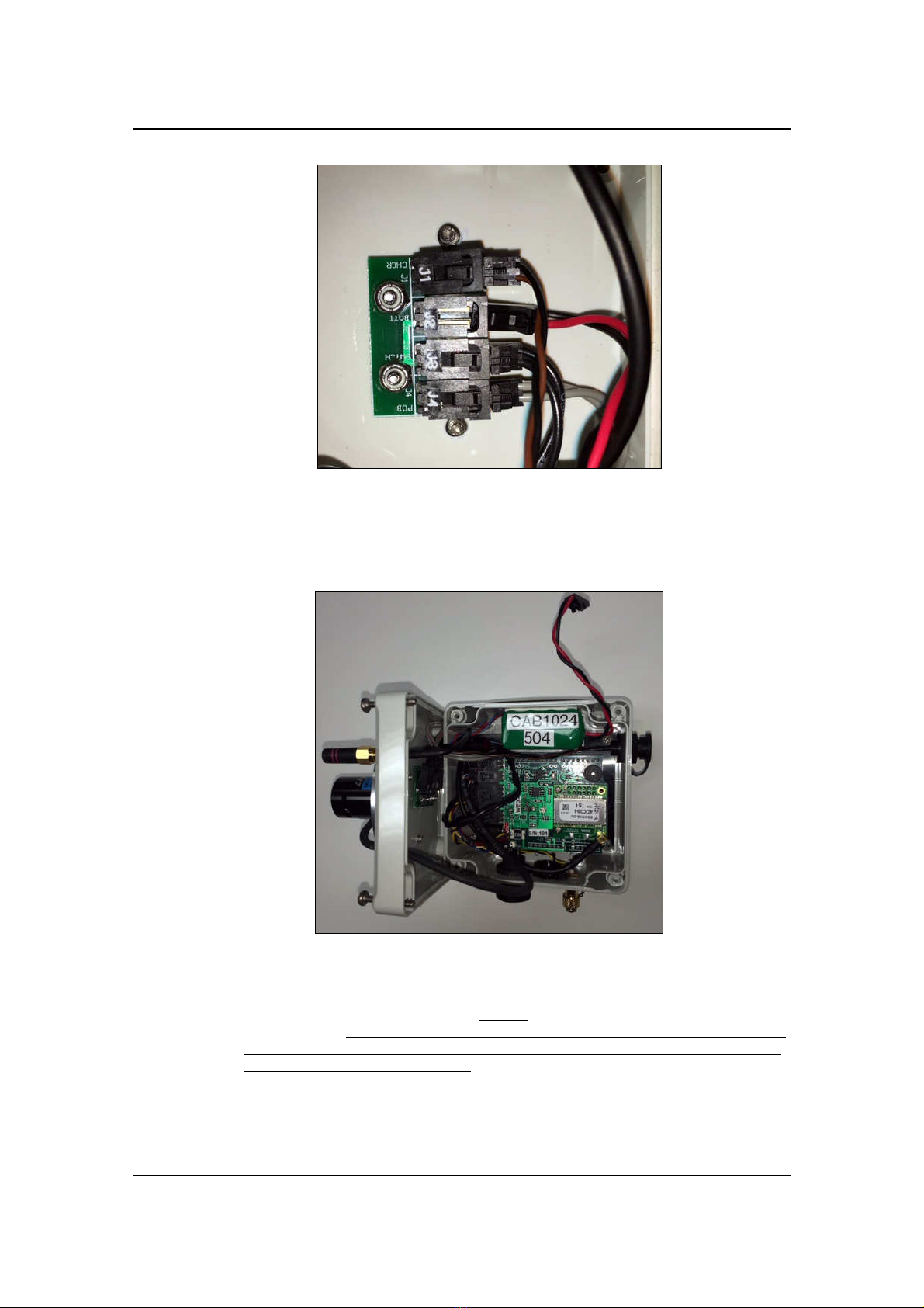
•Remove the two-conductor RED/BLACK battery connector from the small PCB that is
attached to the lid of the enclosure. The correct battery connector on the small PCB is
marked “J2” and “BATT”. See the close up photo of the bottom side of the unit lid.
1 6
1 61 6
1 6
SVC WIRELESS EXTERNAL DATA INTERFACE 4 CHANNEL USER MANUAL REVISION 1.0
Figure 24 Battery Replacement - Connector J2 "BATT" Partially Removed
•Once J2 has been removed, the battery has been electrically disconnected from the unit, as
shown below.
Figure 25 Battery Replacement - Old Battery Prepared For Removal
•The old battery is attached to the enclosure side wall with double-sided foam tape. Start the
process of removing the battery by first carefully separating the old battery from the side wall
of the enclosure. DO NOT SE ANY METAL TOOLS FOR THIS OPERATION, as
the battery may be damaged! If necessary, use a thin, stiff plastic tool to slowly work
the battery loose from the side wall.
•With the old battery removed, clean any remaining tape / glue from the side wall.
This manual suits for next models
1
Table of contents
Other SVC GROUP Automobile Electronic manuals

Popular Automobile Electronic manuals by other brands


Parking Zone
Parking Zone MySpot 500 owner's manual

Outback
Outback S2 Quick installation guide

Kuda-Phonebase
Kuda-Phonebase 053030 Installation instruction

Toyota
Toyota 08529-00851 installation manual

Gemini
Gemini KIT Parking Sensor 818W Installation and use manual

Autostart
Autostart AS PRG-1000 user guide