Parking Zone MySpot 500 User manual

Copyright DPC 2017© P/N for this manual is 95-1030
FCC THIS DEVICE COMPLIES WITH
PART 15 OF THE FCC RULES. OPERA-
TION IS SUBJECT TO THE FOLLOW-
ING TWO CONDITIONS: (1) THIS DE-
VICE MA Y NOT CAU SE HA RMFUL
INTERFERENCE, AND (2) THIS DE-
VICE MUST ACCEPT ANY INTERFER-
ENCE RECEIVED, INCLUDING INTER-
FERENCE THAT MAY CAUSE UNDE-
SIRED OPERATION.
THE MANUFACTURER IS NOT RE-
SPONSIBLE FOR ANY RADIO OR TV
INTERFERENCE CAUSED BY UNAU-
THORIZED MODIFICATIONS TO THIS
EQUIPMENT. SUCH MODIFICATIONS
COULD VOID THE USER’S AUTHOR-
ITY TO OPERATE THE EQUIPMENT.
CE HEREBY, DESIGNATED PARKING
CORP., DECLARES THAT MYSPOT
500 IS IN COMPLIANCE WITH THE
ESSENTIAL REQUIREMENTS AND
OTHER RELEVANT PROVISIONS OF
DIRECTIVE 1999/5/EC. A COPY OF
THE STATEMENT OF CONFORMITY
CAN BE FOUND ON THE COMPANY’S
WEB SITE.
Rudor M. Teich, President
W A R R A N T Y A N D L I A B I L I T Y
STATEMENT
The MySpot 500 and all of Desig-
nated Parking Products are sold
subject to all the terms and condi-
tion defined on our web sites un-
der Terms and Conditions.
Under no circumstances will DPC
be liable for consequential dam-
ages or for costs in excess of the
original price paid to Designated
Parking.
PATENTS
The design of the MySpot 500 is
covered by US Patent 9,464,392
TRADE NAME: MySpot is a regis-
tered trade name of Designated
Parking Corp.
MySpot™500 version V1
Remote Controlled Parking Barrier
Congratulations!
MySpot 500 rug-
ged construction,
careful design and
attention to detail
will provide you
with years of ser-
vice and enjoy-
ment. However,
like all things me-
chanical and elec-
tronic, proper in-
stallation and use
are essential in
order for the prod-
uct to perform as designed.
MySpot 500 is installed in the
middle of the space to block ac-
cess to a parking space.
On command, the barrier is ro-
tated down away from the incom-
ing car to allow access to the
parking space. A second com-
mand will raise the barrier to the
vertical position where it guards
the space.
Owner Manual V1.02
We suggest that you keep this manual in the car’s glove compartment,
The manual will refresh your memory how to use the barrier, as well as
show you how to recognize when the batteries need replacing and how
to go about it.
WARNING! Barrier may cause pe-
destrians or users to trip over it.
Please install and provide warning
signs accordingly. Note that Public
Liability should be in place.
The product has advanced fea-
tures many of which are covered
in this manual.
Pacific Cascade Corporation
14208 NW 3rd Court, Suite 200
Vancouver, WA 98685
P: 360-574-9313 F: 360-574-9325
www.parkingzone.com

For assistance in using, installing, programming or troubleshoot-
ing, we recommend that you look up our video clips on You-
Tube.com Search using the term “MySpot 500 support”.
IMPORTANT
DEFENSE
The MySpot 500 barrier is designed
to absorb external frontal forces and
yield if they exceed a dangerous
point. The barrier will return on its
own to the upright position once the
external force has been removed.
The Defense works in both direc-
tions —if the barrier is forced to-
wards the back of the parking space,
or if it is forced towards the front of
the parking space.
WARNING: The internal defense
spring can store damaging energy
when the barrier is abruptly re-
leased.
MANUAL RELEASE
If the barrier is stuck in the up or
down positions, you can release
the locking mechanism manually.
Use the M8 open-wrench to re-
move the vent in the back of the
housing, then insert the long arm
of the M3 hex wrench into the
housing until you hit the brake.
Apply a sideways force to the
left. This will force the brake to
the right (the hole in the housing
acts as a fulcrum). While holding
the brake in this position, manu-
ally lower or raise the barrier.
LOW BATTERY SIGNAL
When the unit detects that the
battery is nearly discharged, the
barrier will “hesitate” for one sec-
ond at 45 degrees every time it is
commanded to go down. After 50
such warning cycles, the barrier
will refuse to go up any further,
until the batteries have been re-
placed.
the batteries and measure the
voltage across each one. The
voltage must be above 1.3 volt.
We recommend replacing a set of
batteries if any is below 1.40V to
save maintenance next time.
Fresh batteries should read over
1.55V.
There can be other reasons;
please consult our online trouble-
shooting wizard.
Barrier does not rise/drop fully
This is an indication that there is
resistance that blocks the move-
ment of the barrier, or causes the
barrier to move slower than
usual. Watch the LEDs in the
front of the barrier. Send a com-
mand; the barrier should move
without the RED LED flashing
until it is stopped at the end of
travel (vertically up of horizontally
down).
A possible reason for slow move-
ment or failure to reach the full up
and down positions may be due
to the barrier being bent/
misaligned (after a car bumped
into it).
Barrier does not lock in the Up
position
If the barrier moves properly and
reaches the vertical position, but
offers no resistance against push-
back at that position, there may
be a failure of the internal barrier
lock.
Contact the factory or your dis-
tributor.
Use of the Wizard
Visit our online self-diagnosing
wizard at:
http://designatedparking.com/
TS_500MS/index.php
The wiki is symptom driven. Find
the symptom, then navigate to
either more questions or to the
solution by clicking on the appro-
priate entry.
Troubleshooting continued

Troubleshooting
DIAGNOSTICS LEDs
The MySpot 500 has 2 LEDs
in the front panel, visible
through a clear hole in the yel-
low “reserved” label. The loca-
tion is immediately to the left of
the “S”. One LED is green and
the other is red.
BARRIER IS DOWN, Does
not rise on command
press the center button on the
remote and observe the LEDs.
If the red LED flashes in re-
sponse to the command, it
means that the remote is not
paired with the barrier.
One cause can be a mix-
up between remotes
paired for different barriers
Another cause can be the
introduction of a new re-
mote that was not previ-
ously paired.
A 3rd possibility is that the
barrier unit was rebooted
and thus lost it pairing his-
tory.
See page 5 for pairing pro-
cedures.
If the green LED flashes in re-
sponse to the command, it
means that the radio link is OK
and the cause of the problem
could be one of the list below:
The barrier is mechanically
prevented from rising (Red
LED will flash during move-
ment)
The position sensor informa-
tion inside the barrier unit
got corrupted. Reset the
power to the unit (see page
15), then send a couple of
commands to exercise the
barrier up and down.
If neither LEDs flashes, a likely
cause for no response is that the
barrier batteries are run down or
that they “jumped” out of the
holder during shipping. Access
CONTACT US for assistance
1-360-574-9313 or
YouTube.com “myspot 500 support”
OPERATION
The MySpot 500 is
prov i ded wi t h 2
handheld remotes
(“fobs”) that have
been factory pro-
grammed to con-
trol this individual barrier. Only
button #2 on these remotes is
pre-programmed to control the
barrier.
The fobs will control the barrier
from a distance of 1 foot to 40
feet (0.3 meter to 12 meters).
You need to hold the fob horizon-
tally and face the front of the bar-
rier (the “Reserved” yellow strip
on the housing of the barrier).
Pressing button 2 on the fob will
raise the barrier if it was down, or
lower it if the barrier was up.
If the barrier hits resistance on its
way up, it will stop and reverse
itself to bring the barrier back
down. If the barrier hits resis-
tance on the way down, it will
stop and await a new command.
Before You Install
BEFORE YOU OPEN THE CARTON:
If external damage to the packing is evident, notify the carrier immediately.
Shipping damage is not covered by the manufacturer’s warranty.
KIT CONTENTS
The kit includes the following.
Flat open wrench M8
Hex L wrench M3
4 concrete expansion anchors
2 HTm remote control fobs
This manual
TOOLS REQUIRED—CONCRETE
The following tools are require to
install the MySpot 500 on concrete.
Hammer drill
10 mm drill bit
M13 (1/2”) open end wrench
Hammer
TOOLS REQUIRED—ASPHALT
The following tools and supplies are
require to install the MySpot 500 on
asphalt.
AK-4 anchor kit
Hammer drill
7/8” drill bit, 6” long
1/2” open end wrench
Hammer
Grease or anti-seize paste
Installation instructions begin on
page 7.

Remote’s Features
The HTm (Hand
T r a n s m i t t e r )
remote offers an
array of features
uni que i n th e
industry. In this
s e c t i o n w e
cover some of
these features.
Toggle vs. Discrete Com-
mands
Toggle commands instruct the
barrier to alternately go up and
go down. This is the standard
configuration for the barrier and
the HTm.
Toggle commands are a simple
and effective way to control the
barrier when it is in line of sight.
You know that if the barrier is
down and you send a command,
the barrier will go up, and vice
versa.
There are applications where
Discrete commands are pre-
ferred. The commands are Up
and Down. If one sends an Up
command and the barrier is up,
the command will be ignored.
Likewise, when the barrier is
down, a Down command will be
ignored.
Discrete commands are available
when using the PK250 long-
range transmitter.
1 or 2 Button Code?
The HTm is shipped in the mode
where only one button is required
to be pressed. For applications
where more than 3 adjacent bar-
riers need to be controlled, the
HTm can be set to a two-button
mode. Up to 9 adjacent barriers
can be individually controlled. A
command is sent only after the
2nd button was pressed (e.g.
button 2 then button 1).
To program the HTm remote to
the 2-button mode, or to return it
to its 1-botton mode, see page 6.
Pairing
Paring is a procedure whereby a
remote is added to the list of de-
vices that are authorized to con-
trol the barrier. It is similar to the
procedure used to pair your
Smartphone with your car for
hands-free operation.
Why 3 buttons?
Each button on the HTm remote
control generates an individual
code. That allows one remote to
control 3 individual MySpot 500.
The HTm also supports a 2-
button mode of operation. In the
2-button mode, 9 MySpot barri-
ers can be controlled individually.
RESET
Reset is achieved by momentarily
removing power from the electronics
in the barrier unit.
1. Follow the steps to gain access
to the battery holder (page 11)
2. Pull out the battery closest to
you, and reinsert it 5 seconds
later.
3. After the power has been re-
stored to the unit, watch the
green and red LEDs in the front
of the unit just to the left of the
“S” in “RESERVED”.
4. The sequence of light flashes
identifies the software revision
level. Revision 1.4.1 will flash
green once, red 4 times followed
by green 1 time. This is followed
by 10” of no activity, then 3 quick
red flashes indicating that the
unit is ready to respond.
REBOOT
1. Follow the steps to gain access
the battery holder (page 11)
2. Pull the battery holder as far as it
will go, exposing all 5 battery
cells.
3. Reach behind the wall of the
holder. You will feel a push
switch. Push the switch towards
you and hold it for 7 seconds,
then release it
4. If the reboot was successful, you
will see a light show of the green
and red LEDs where they flash
alternately 6 times. This will be
followed by the power up light
show (see Reset on the left)
5. After the reboot, send a com-
mand from the remote of your
choice. This will automatically
pair that remote with the barrier.
Reset & Reboot

The MySpot 500 is supplied
with the HTm fobs.
NOTE:
The HTm uses 2 CR2032 bat-
t e r i e s i n t w o
separate hold-
ers.
Remote’s Battery Replacement
To rep lace the batteries,
open the small Philips screws
on the back of the unit. Re-
place the Lithium button bat-
teries with the suitable battery
as list on the left. Observe
polarity! The outer housing
of the batteries should be on
the top.
Check operation of the indi-
cator before closing he hous-
ing. If OK, close with the
screws
Adding Remotes
ceeded, the paring sequence
will be aborted and the red
LED will flash once.
4. If the step was performed
within the required time and
in the proper sequence, the
Green or Red LED will flash
a number of times indicating
the completed step count (1
to 4).
Step 1: With the barrier down,
stand on the barrier and send a
Green command (from the pre-
paired HTm). The green LED on
the barrier housing will flash
once.
Step 2: As soon as the LED on
the HTm has turned off, send
another Green command (from
the pre-paired remote). The
green LED on the barrier housing
will flash 2 times.
Step 3: As soon as the LED on
the “green” HTm has turned off,
send a Red command (from the
un-paired remote). The red LED
on the barrier housing will flash 3
times.
Step 4: As soon as the LED on
the HTm has turned off, send a
Green command (from the pre-
paired remote). The green LED
on the barrier housing will flash 4
times.
The new remote has now been
paired and can control the barrier
just like any “green” remote.
Pairing links a remote to the bar-
rier. When an un-paired remote
sends a command to the barrier,
the barrier will not move in re-
sponse to the command as this
command has not been author-
ized. The red LED on the front of
the barrier will flash for 1/2 sec-
ond to acknowledge the signal.
We refer to un-paired but other-
wise valid signals as RED com-
mands.
When a paired command is re-
ceived, the green LED will flash.
And the barrier will move. We
refer to these as GREEN com-
mands.
Pairing Procedures
Pairing a new remote is a 4-step
procedure. It requires a previ-
ously paired HTm and the new
remote to be paired. We refer to
the pre-paired remote as the
GREEN remote and to the new
one as RED remote.
Preparations:
1. Bring the barrier down using
the Green remote
2. For the duration of the pair-
ing procedure, stand on the
barrier to prevent it from ris-
ing
3. Each step must follow its
predecessor within 5 sec-
onds. If the time was ex-

Special Configurations
The only way to delete remotes
that were previously paired with
the MySpot 500 is to erase all the
paired remotes from the memory
of the barrier. This is also the
case when all the paired remotes
have been lost, and a replace-
ment remote needs to be added.
This erasure is known as a
“Boot”.
Boot can be done by pressing an
internal “Boot” switch at the back
of the battery holder. See page
13.
Boot can also be done remotely,
using the PK250 keypad remote
controller, but only if the PK250
was previously paired with the
barrier. Another way is to pair a
total of 16 HTm. When the 16th
is added, a boot occurs.
This procedure is only applicable
immediately after the MySpot
was booted and its memory was
erased. The MySpot 500 are
delivered with 2 remotes which
have already been paired. If you
need to add more remotes, see
the procedure “Adding Remotes”
on page 5.
To pair a remote after a boot,
send two commands from the
remote. The first command will
be acknowledged as a RED flash
on the LED in the housing. The
Erase Memory (Boot)
Pairing After Boot
next command will be acknowl-
edged as a GREEN flash.
The barrier has now been paired
with its first remote.
Please keep this remote in a safe
place. It can be used to author-
ize additional pairing. If you have
paired 2 or more HTm with the
barrier, any one of them can au-
thorize additional remotes.
To place the HTm remote in the 2
-button mode (where a sequence
of 2 keys is required before a
command is sent out):
Press and hold buttons 1& 2
simultaneously.
After 5 seconds, the indicator
on the HTm will start flash-
ing. Release the buttons.
Make sure that the indicator
continues to flash.
Press button 2and hold until
the flashing indicator turns
off.
To place the HTm in the 1-button
mode, follow the sequence above
but as the last step press and
hold button 1.
TEST: Press any button once.
IF the indicator responds immedi-
ately, you are in 1-button mode.
Program 2 Button Mode
fresh D alkaline batteries.
We recommend Duracell.
8. Observe the polarity of the 5
batteries as you insert them.
Failure to do so will damage
the electronics.
9. Place the holder cover and
secure with the 2 screws.
The cover is not symmetrical
—it has a tab on one end
that fits over the boot switch
assembly. Also note that
you need to snap the cover
into the base so that the 2
holes in the cover align with
the holes in the holder.
10. Gently push back the battery
holder until it is fully inside
the housing.
11. Rotate the arch back to its
place at the end of the hous-
ing. Make sure that the gas-
ket 87 is positioned and
aligned between the end cap
and the housing. The align-
ment needs to be perfect to
prevent water damage.
12. Use the longer (20 mm)
screw for the top hole, using
the nylon washer under the
screw head. Likewise insert
the 2 short 10 mm screws
into the other 2 holes in the
bracket using the nylon
washers.
13. Verify that the gasket is
straight and did not slide
down and is thus completely
Battery Replacement continued
The picture above shows the
components of the bearing as-
sembly of the cover to the bat-
tery compartment. DO NOT
remove screw 93; all the parts
stay as an assembly as you
rotate the arch
aligned with the housing and
the bracket..
14. Tighten all 3 screws as hard
as you can.
Failure to use the 3 nylon
washers will allow water to
seep into the housing and
damage the electronics.

3. If the barrier does not re-
spond (due to low batteries),
use the emergency key to
release the brake (see page
2).
4. Rotate the barrier as shown
and pull out the
battery holder so
that the holder is
free outside the
housing.
5. Be careful not to
move the rubber
gasket that is
attached to the end cap.
6. Remove the battery holder
cover by opening the 2
s c r e w s
at the
end of
t h e
holder.
7. Replace
the bat-
t e r i e s
with 5
The 5 batteries should provide 2
to 3 years of life under residential
operating conditions. When the
batteries approach their end-of-
life, MySpot 500 will stop for 1
second midway on its way down.
If the batteries are not replaced
before they are completely ex-
hausted, after 50 additional op-
erations, the barrier will accept
one last command and will stay
down .
To replace the batteries:
1. Loosen the right hand end
cap by removing 3 round
head hex screws using the
provided 3 mm hex wrench
2. If the barrier is in the way of
accessing one of the screws,
use the remote to rotate the
barrier and stop the barrier
manually when the screw
becomes accessible.
Battery Replacement
Positioning the Barrier
Barrier Footprint
The barrier is positioned so that the
“RESERVED” label faces the en-
trance to the parking space. When
the barrier is lowered (shown above
in the lowered position), the barrier
rotates away from the entrance.
FRONT VS. MIDDLE
MySpot 500 can be positioned in two
distinct locations within the parking
space –in the middle or at the front.
Front mounting
means that the car
drives in and parks
behind the barrier.
A benefit of front
mounting is that the
barrier can be used
as a theft deterrent,
raising it with the car
parked behind it.
The barrier should be installed close
to the front end of the space, to allow
the barrier to rise behind even a
large vehicle. In order to raise the
barrier with the car in place, you
need a clearance of 0.65 meters
(25”) between the bumper and the
base of the barrier.
Installing the barrier at the front in
multi-car parking areas will increase
the likelihood that the barrier will be
bumped by cars backing up from
parking spots across the aisle and is
not recommended.
Middle mounting means that the
barrier will stay under the car while
the car is parked in the space. The
advantages of middle-mounting are:
The barrier is further removed
from dirt and debris pushed from
the main access lane
Cars making J turns are less
likely to bump into the raised
barrier accidentally
Cars entering adjacent lanes are
less likely to accidentally hit the
barrier
When placing the barrier in the mid-
dle of the stall, the center line of the
device should be about 1.5 meters (5
feet) from the rear of the stall.
STANDING WATER
MySpot 500 is sealed to prevent
water from entering the unit. How-
ever, the housing should not be ex-
posed to standing water or ice as it
will materially reduce the range of
the remote control signal.
Select a spot for the housing that is
slightly raised above the surface, or
add a plate to raise it. Be mindful of
the added height if low-clearance
cars are to use the space

Installation on Concrete
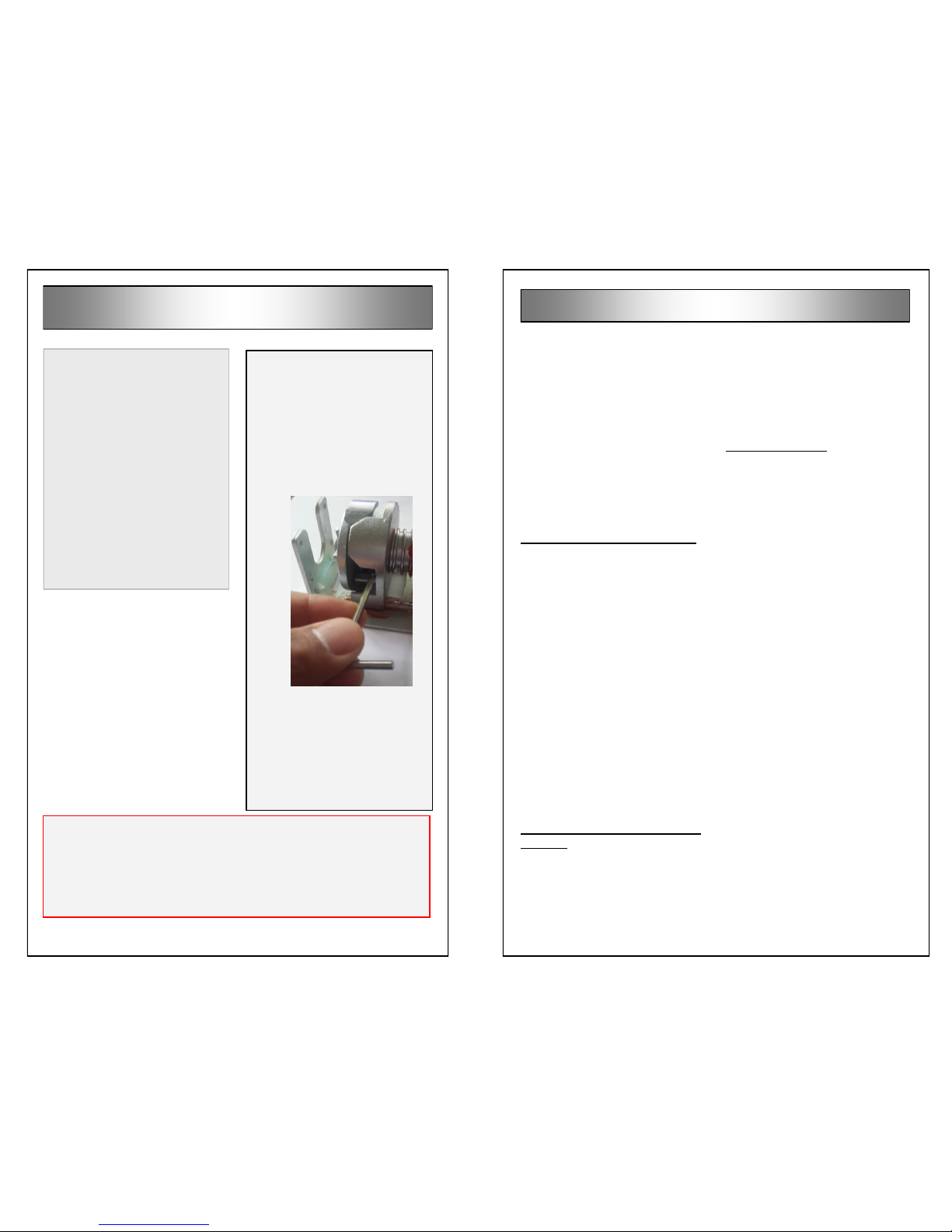
1. While standing on one of the
mounting ears of the housing,
use the remote to bring the bar-
rier up to the vertical position.
Make sure that the barrier has
exited the Hibernation mode
(see above).
2. Place the barrier at the location
you selected.
3. Mark the 4 holes using the
mounting ears as
your template
4. If you are installing
on concrete or
other masonry surfaces, use the
expansion anchors that are pro-
vided in the MySpot 500 kit.
5. Drill four 10 mm (3/8”) holes, 65
mm (3”) deep.
6. Push the anchor into the hole
until its washer is resting on the
surface, DO NOT HAMMER
THE ANCHOR IN! The anchor
will collapse and be destroyed.
7. If the anchor does not slip into
the hole, re-drill the hole while
moving the drill from side to side
to slightly enlarge the hole.
8. Tighten the bolt a couple of
turns until the anchor bites into
the concrete walls. This will
prevent the anchor from rotating
freel y l at er, or from falling
deeper into the hole.
9. Before removing the bolt (to
attach the barrier), clean the
area around the anchor so that
no debris will enter the thread,
10. Remove the bolts, place the
barrier assembly over the an-
chors and use the washer and
bolts to secure the assembly to
the anchors.
11. Tighten the bolts to make sure
that the anchors are holding fast
and to prevent the bolts from
loosening up over time.
If an anchor rotates in its seat:
If the hole is only slightly oversize,
use a sharp point to hold the an-
chor against the wall of the hole
and gently tighten the bolt. At
some point, the expanding anchor
will grip the walls of the hole. Turn
the bolt another ½ turn to make
sure that the anchor is set.
If the hole is too large, you may
need to fill it with a concrete mix or
epoxy, and then re-drill once the
mixture has hardened. Inserting
the anchor into the still-liquid ep-
oxy may fill the threads and pre-
vent the anchor from accepting the
bolts. If the bolt is placed while the
filler is not yet hardened, it may not
be able to be withdrawn later.
You may also order DPC MA516
anchors, as these require a 16 mm
(5/8”) hole, and thus can be re-
drilled in the same location.
IMPORTANT!!!
The barrier is shipped in Hiberna-
tion mode. To wake the unit up,
send a series of 10 commands in
quick succession.
Once the barrier responds with a
red or green LED flash, the unit is
in normal mode and will respond
to single commands.
Installation on Asphalt
1. Do not attempt to use the ex-
pansion anchors that are pro-
vided in the kit for installation on
asphalt. The expansion anchors
are guaranteed to loosen up in
a matter of hours.
2. We strongly recommend that
you use our AK-4 asphalt an-
chor kit, designed specifically
for mounting the MySpot 500 to
asphalt surfaces. The kit con-
tains 4 SP10 anchors with bolts
preinstalled, and 2 bags of
grout.
3. If you expect to have to remove
the barrier for snow plowing, for
example, we strongly recom-
mend that you apply grease to
the bolt thread. Even better is
anti-seizing paste.
4. Drill a 22 mm (7/8”) hole, 150
mm (6”) deep.
5. Clean the area.
6. To activate the grout, add under
a 1/4 cup of water to the bag
and mix thoroughly by kneading
the bag.
7. Use the bag to pour the grout
into the hole, filling it to the top.
8. Do not remove the bolts from
the anchors. Press or gently
hammer the anchor into the hole
until it is flush with the asphalt.
(The head of the anchor will rest
on the asphalt.) Do not delay
this step as the grout cures
within 10-15 minutes.
9. Wipe any excess grout from
around the anchor.
10. 15 minutes after the last step,
remove the bolts from the an-
chors and install the barrier.
11. We recommend applying heavy
grease or alumi-
n um a nt i-s e i ze
paste (Permatex
8 0 0 7 8 ) t o t h e
th r ea d s o f the
bolt before insert-
i ng i t i nt o t he
anchor. This reduces rust and
facilitates removal of the bolts in
the future.
12. Use a 1/2” wrench to tighten the
bolts.
Seasonal Removal
If you need to remove the barrier often
(e.g. for snow removal), we suggest the
use of stainless steel bolts to attach the
unit to its anchors. As a minimum, fill
the anchor thread with heavy grease
before screwing in the bolts.
If you installed on asphalt using our
SP10-38 anchors, we offer Thread-
Guards (P/N 53-0208) that snap tightly
to the opening and protect the thread.
The ThreadGuards are essentially flat
on top so that they will not present a
tripping hazard.
Table of contents