PAGE 04 - USER MANUAL USER MANUL - PAGE 05
To time-activate the sensors, a parameter must be be modified (see chapter “setting of
parameters).
When the setting is modified, the OFF sign is not displayed when the left hand side
push-button is pressed because the sensors will automatically activate when ignition is
turned on again.
Engagement of the reverse gear activates the rear sensors but also the front sensors if
they are programmed to work on a “time-activation” basis.
On some vehicles, when speed exceeds 10Km/h, no icon could be displayed even
though the system is active.
The sensors can still be deactivated with the push-button.
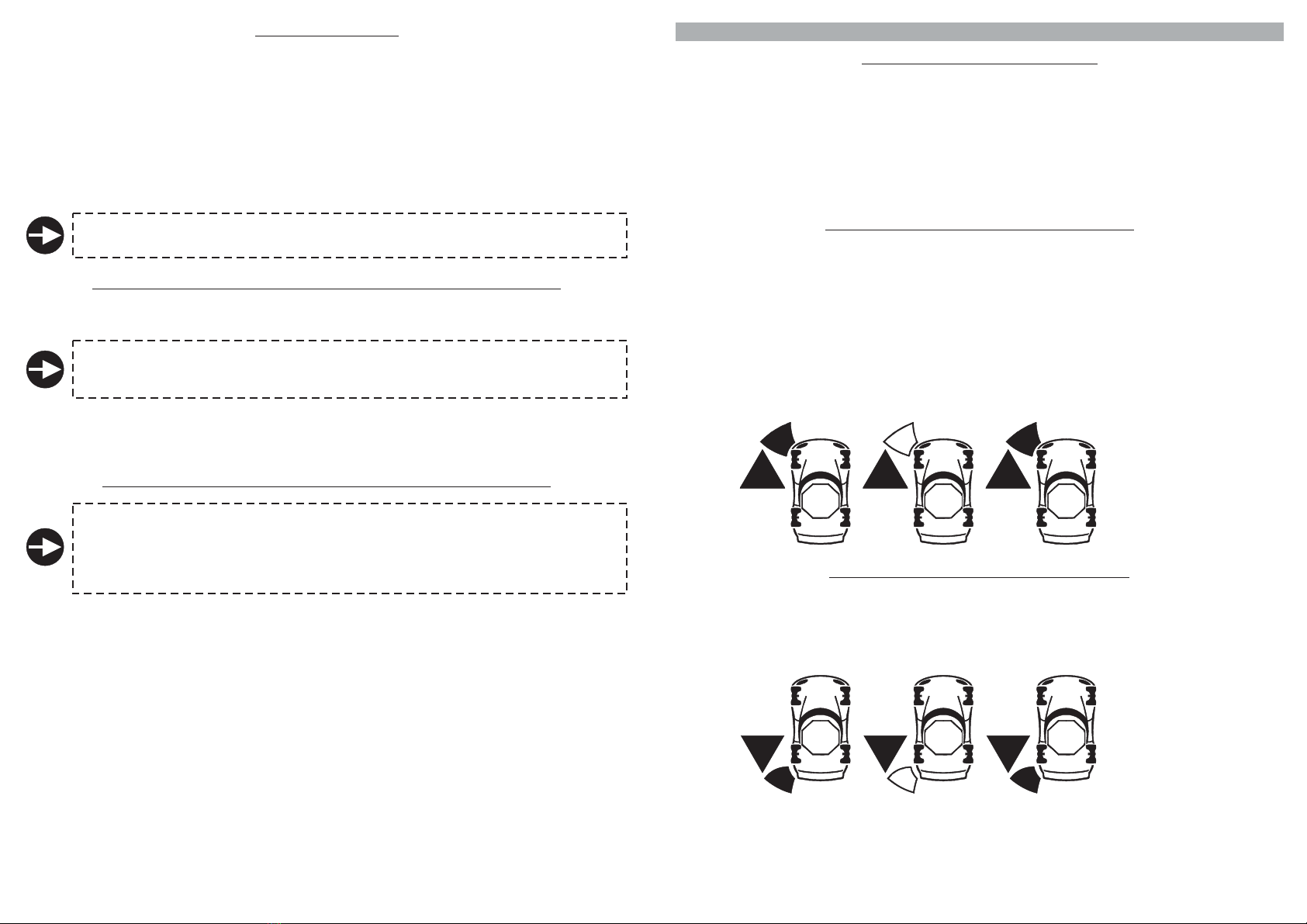
The front sensors are activated by turning on ignition; an upward arrow icon will light up on the display
to indicate activation.
directly related to the setting of the
To deactivate the sensors, simply press the display left-hand side push-button; the upward arrow icon
on the display will turn off
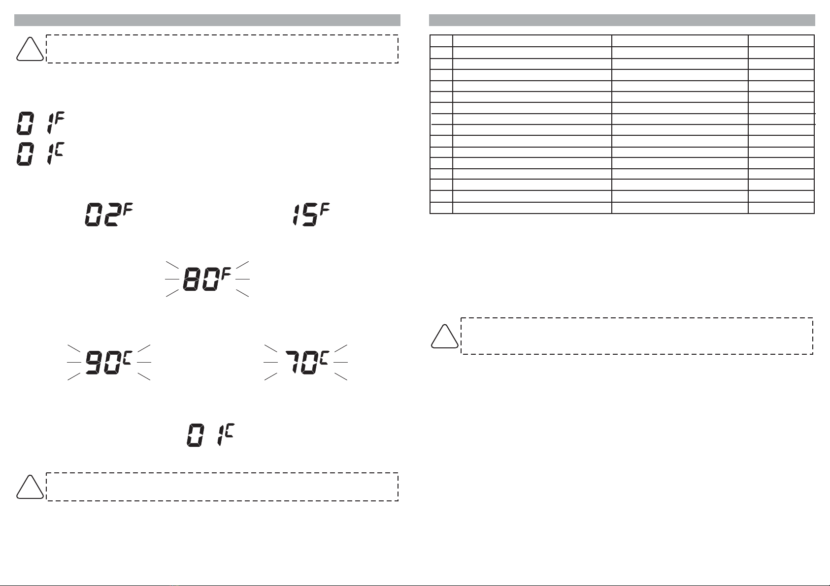
time setting preset time delay “0”
Functioning is parameters.
.
By modifying the of the front sensors (function 13, ), the front sensors
will work as follows:
If, within the preset time, no obstacle is detected in front of the vehicle, the sensors will
automatically be deactivated.
If, within the preset time, the obstacle is still detected, the sensors will remain active as long as the
obstacle is detected and will deactivate 3” after detecting the last obstacle.
If you need to use the front sensors again after the automatic deactivation, simply press the left
push-button.
The sensors will automatically deactivate 3” after detecting the last obstacle.
!
!
!
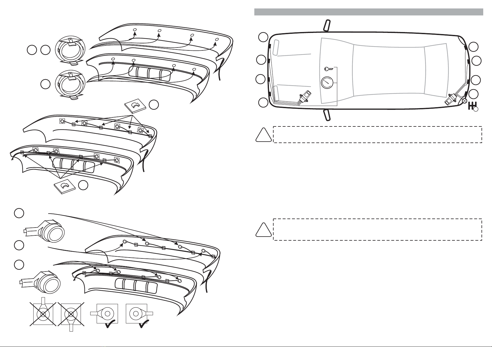
2.2 - REAR SENSORS
The rear sensors are activated when reverse gear is engaged; an audible signal
.
To reactivate them, simply press the same button
warning and the
downward arrow icon that lights up on the display will indicate the sensors are active.
Obstacles are signaled by different audible tones and the lighting up of the relative detection zones
and distance on the display.
The faster the beeping, the closer the obstacle; a continuous tone indicates the obstacle is extremely
close to the bumper.
To deactivate the sensors (when reverse gear is engaged), simply press the push-button on the right
hand side of the display; the “OFF” sign will light up on the bottom part of the displayed vehicle and the
downward arrow will turn off to indicate the sensors are deactivated
.
In case of need (vehicles in queue), press the push-button with the upward arrow to deactivate the
sensors.
In this case the “OFF” sign will light up on the displayed vehicle.
2.3 -
.
AUTOMATIC ACTIVATION OF FRONT SENSORS (odometer signal)
Front sensors are activated whenever ignition is turned ON and are automatically deactivated when
speed exceeds about 15Km/h
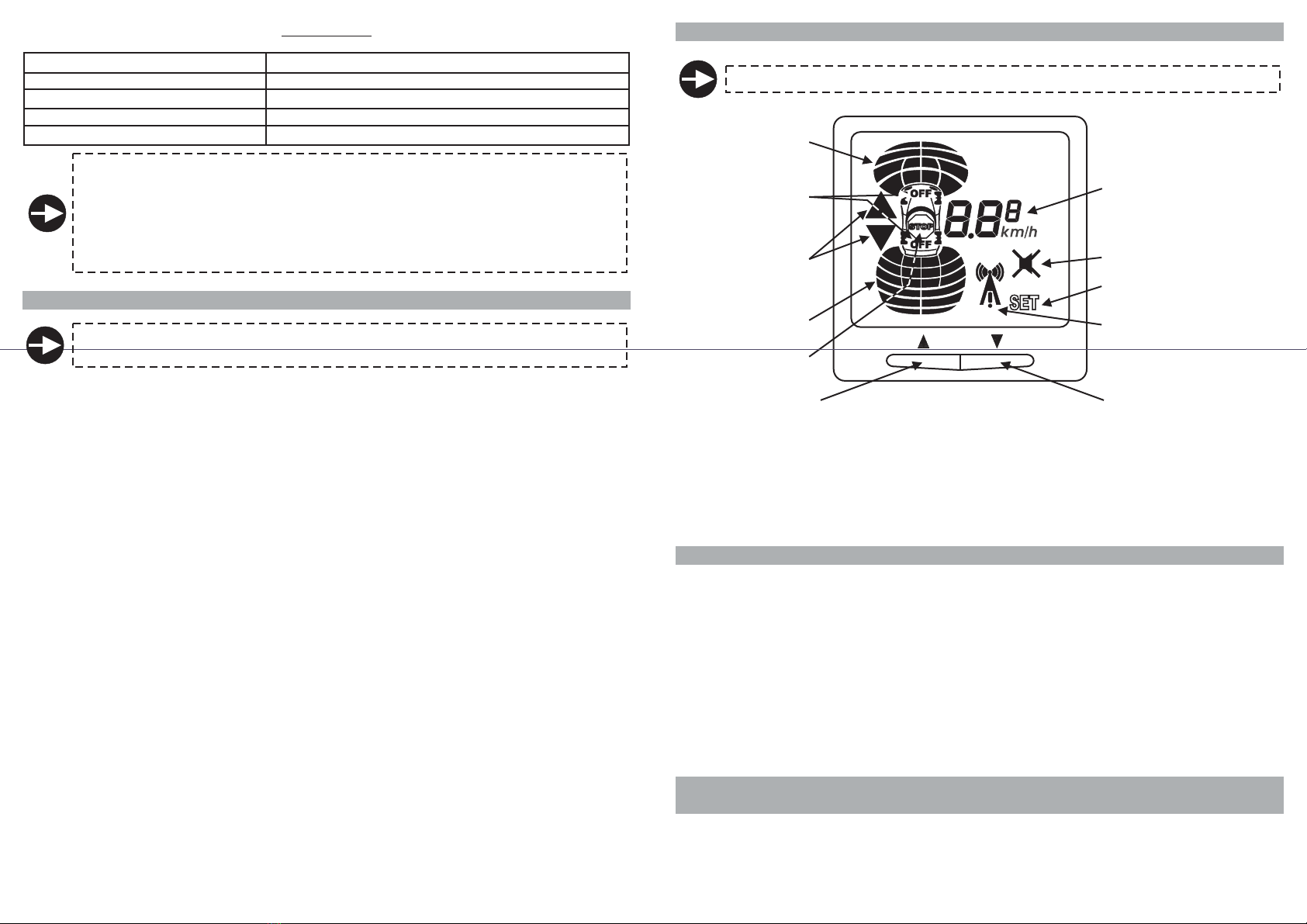
3.0 - TROUBLESHOOTING GUIDE
3.1 - LOW POWER SUPPLY SIGNAL
If, when the system is turned on, the battery level is too low to guarantee the accuracy of the system,
).
after a few seconds, the following icons will be displayed: vehicle, front sensors arrow icon and four
front detection zones closest to the bumper.
The arrow and the detection zones icons will flash for about 8/10 seconds.
This will inform the driver that ALL sensors are deactivated and that he will have to carry out reversing
and parking manoeuvers without the help of the sensors.
When nominal tension is restored, the rear sensors will start working normally.
To activate the front sensors, cut and restore supply to the front control unit (turn ignition off and on
2.4 - )TIME-ACTIVATED FRONT SENSORS (odometer not connected
3.2 - FRONT
.
).
SENSORS ANOMALY INDICATION
If one of the sensors turns out to be inoperative or disconnected, a few seconds after the control unit is
turned on, the following icons will be displayed: vehicle, front sensors arrow and inoperative sensor (or
sensors)
If parameter 13 has not been modified and is set to “0”, the front sensors arrow and detection zones
will flash as long as the control unit remains active.
If, on the other hand, parameter 13 has been modified, the front sensors arrow and detection zones
will flash for about 8/10 seconds.
All other sensors will operate normally.
If one of the rear sensors turns out to be inoperative when reverse gear is engaged, the front sensors
arrow and inoperative sensor (or sensors) icon will flash as long as reverse gear is engaged (and 8/10
seconds after reverse is disengaged
3.3 -
.
REAR SENSORS ANOMALY INDICATION
If one of the sensors turns out to be inoperative or disconnected, a few seconds after reverse gear is
engaged, the following icons will be displayed: vehicle, rear sensor arrow and inoperative sensor (or
sensors).
The arrow and the icon relative to the inoperative sensor will flash as long as reverse is engaged; all
other sensors will work normally
Rear sensor 5
inoperative;
sensor icon
flashes.
Front sensor 1
inoperative;
sensor icon
flashes.