manuals.online logo
Brands
  1. Home
  2. •
  3. Brands
  4. •
  5. SVS-Vistek
  6. •
  7. Digital Camera
  8. •
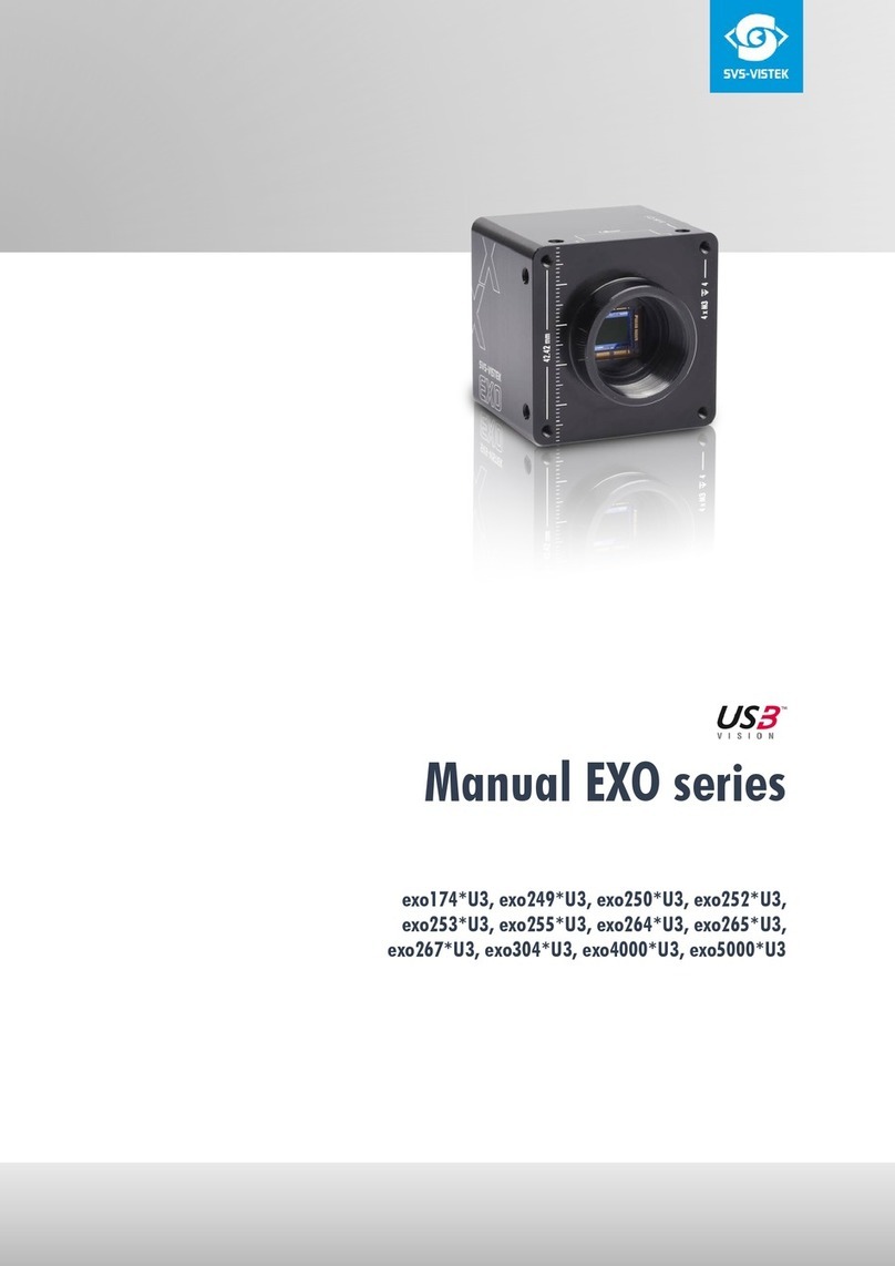
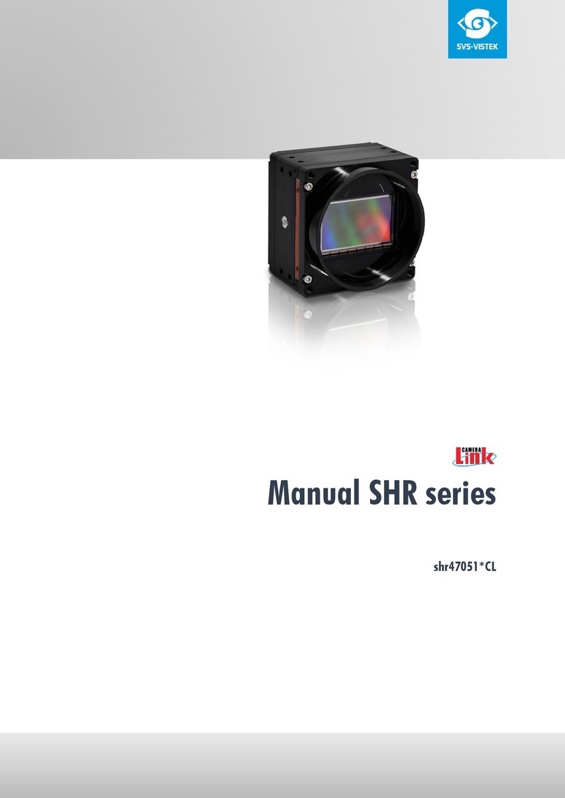
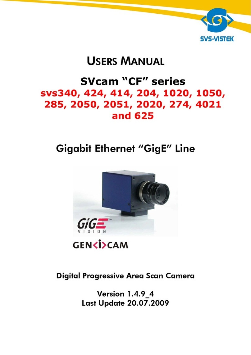
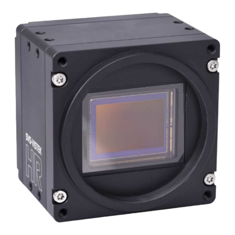
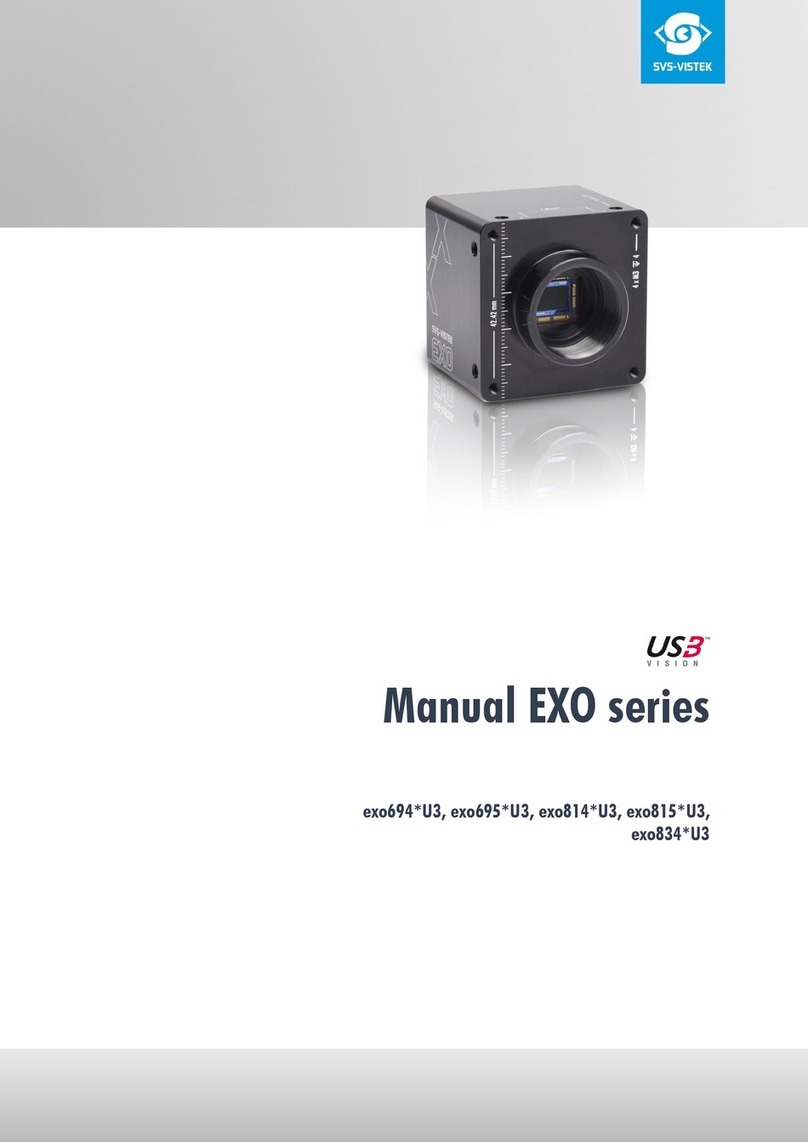
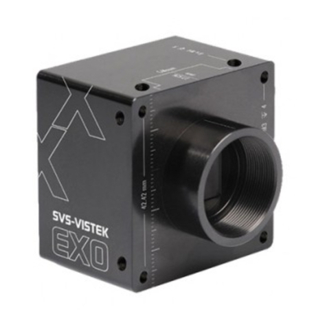
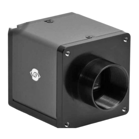
  9. SVS-Vistek GigE EXO Series User manual

SVS-Vistek GigE EXO Series User manual

ManualEXOSeriesGigE
exo174,exo183,exo183TR,exo249,exo250,exo250Z,exo253Z,exo264,exo265,
exo267,exo273,exo304,exo304TR,exo342,exo367,exo367TR,exo387,exo387TR,
exo428,exo540,exo541,exo542,exo545,exo547,exo990,exo4000
Content
1 Companyinformation 5
1.1 Standards 5
1.2 Disclaimer 5
1.3 Copyrightnotice 6
2 Legalinformation 7
2.1 USAand Canada 7
2.2 Europe 7
3 TheEXO series 8
3.1 4I/O addslight and functionality 8
3.2 Lenscontrol 10
3.2.1 TheTracer addsdynamic lenscontrol 10
3.2.2 Useliquid lenson C-mount 11
3.2.3 Useof Canonlenses 11
4 Connectors 13
4.1 GigEIPSetup 13
4.1.1 Automaticcamera detection 13
4.2 GigEVision 15
4.2.1 Network(TCP/IP) 15
4.2.2 XMLfiles 17
4.3 HiroseI/O connector 18
5 Gettingstarted 19
5.1 Gethelp 19
5.2 Find camera specs 19
5.3 Power supply 19
5.3.1 Power safety 19
5.3.2 Connectthecamera 19
5.4 Camera statusLED codes 20
5.5 Softwareand firmware 21
2
5.5.1 SVCapture2.x 21
5.5.2 Softwaredevelopmentkit 25
5.5.3 Firmwareupdate 26
6 Featuredescription 28
6.1 Basicfeatures 28
6.1.1 Gain 29
6.1.2 Resolution 29
6.1.3 Offset 30
6.1.4 Color 31
6.1.5 Flip image 31
6.1.6 Binning 33
6.1.7 Decimation 34
6.1.8 GenICam 36
6.1.9 Trigger modes 37
6.1.10 Shutter modes 40
6.1.11 Exposure 45
6.1.12 Exposurespeed 45
6.1.13 Auto exposure 46
6.1.14 Acquisition and processing time 47
6.1.15 Bitdepth 48
6.1.16 ROI/ AOI 50
6.1.17 Polarized sensor 50
6.2 Camera features 54
6.2.1 IR/ glassfilter 54
6.2.2 Shading correction 55
6.2.3 Defectpixel correction 58
6.2.4 Look-up table 62
6.2.5 ROI/ AOI 64
6.2.6 Basiccapturemodes 65
6.2.7 Micro Four Thirdslenses 66
6.2.8 Read-outcontrol 67
6.2.9 Temperaturesensor 68
6.2.10 Systemclockfrequency 68
6.2.11 Pixel clockfrequencyselection 68
6.2.12 Predefined configurations(user sets) 68
6.2.13 Read-outcontrol 69
6.2.14 Burst mode 70
6.2.15 PrecisionTimeProtocol 71
6.3 I/O Features 73
6.3.1 GenICam 73
3
6.3.2 Assigning I/O Lines– IOMUX 74
6.3.3 PWM 80
6.3.4 LED strobecontrol 84
6.3.5 Sequencer 86
6.3.6 Optical input 91
6.3.7 PLC / Logical operationoninputs 91
6.3.8 Serial data interfaces 93
6.3.9 Trigger-edgesensitivity 94
6.3.10 Debouncing trigger signals 95
6.3.11 Prescale 97
7 Dimensions 98
7.1 C-mount 98
7.2 exo428GE 99
7.3 exo183GETR, exo304GETR 102
7.4 exo267GE, exo304GE, exo253ZGE 104
7.5 exo250GE, exo264GE, exo264ZGE, exo265GE 108
7.6 exo4000GE 111
7.7 exo174GE, exo183GE, exo249GE 114
7.8 exo367GE 117
7.9 exo387GE 119
7.10 exo342GE 122
7.11 exo540GE, exo541GE, exo542GE, exo545GE, exo547GE 125
7.12 exo990GE, exo991GE 127
8 Appendix 130
8.1 I/O driver circuit schematics 130
8.2 IPprotectionclasses 131
4
1 Companyinformation
SVS-VISTEKGmbH
Mühlbachstr. 20
82229 Seefeld
Germany
Tel.: + 49 (0)81 52 9985-0
Fax: + 49 (0)81 52 9985-79
Mail: info@svs-vistek.com
Web: https://www.svs-vistek.com
1.1 Standards
Thismanual isbased onthefollowing standards:
lDIN EN 62079
lDIN EN ISO 12100
lISO Guide37
lDIN ISO 3864-2
lDIN ISO 3864-4
lDIN ISO 16016:2002-5
1.2 Disclaimer
Thismanual containsimportant instructionsfor safeand efficient handling of SVCam
cameras(hereinafter referred to as„camera“). Thismanual ispart of the camera and
must bekept accessiblein theimmediatevicinityof thecamera for anypersonwork-
ing on or withthiscamera.
Read carefullyand makesureyou understand thismanual prior to starting anywork
withthiscamera. Thebasic prerequisitefor safework iscompliant withall specified
safetyand handling instructions.
Accident prevention guidelinesand general safetyregulationsshould beapplied.
Illustrationsin thismanual areprovided for basic understanding and can varyfrom
theactual model of thiscamera. No claimscan bederived fromtheillustrationsin
thismanual.
The camera inyour possessionhasbeen produced with greatcareand hasbeen thor-
oughlytested. Nonetheless, in caseof anycomplaint, pleasecontact your local SVS-
VISTEKdistributor. You will find a listof distributorsin your area on www.svs-vistek.-
com
1Companyinformation 5
1.3 Copyrightnotice
Forwarding and duplicating of thisdocument, aswell asusing or revealing itscon-
tentsareprohibited without written approval. All rightsreserved withregard to patent
claimsor submission of designorutilitypatent.
1Companyinformation 6
2 Legal information
Errorsand omissionsexcepted.
Theseproductsaredesigned for industrial applicationsonly. CamerasfromSVS-
Vistek arenotdesigned for lifesupport systemswheremalfunction of theproducts
might result inanyrisk of personal harmor injury. Customers, integratorsand end
usersof SVS-Vistek productsmight sell theseproductsand agreeto do so at their own
risk, asSVS-Vistekwill not takeanyliabilityfor anydamagefromimproper use or
sale.
2.1 USAandCanada
Thisdevicecomplieswithpart15 of theFCC Rules. Operation issubjectto thefol-
lowing conditions: (1)Thisdevicemaynotcauseharmful interference, and (2)this
devicemustaccept anyinterferencereceived, including interferencethat maycause
undesired operation.
NOTICE ThisequipmentiscompliantwithClassAofCISPR32. Ina residentialenvironment
thisequipmentmaycauseradiointerference.
Thisequipment hasbeen tested and found to complywiththelimitsfor a ClassA
digital device, pursuant to part 15 of theFCC rules.
It isnecessaryto usea shielded power supplycable. Youcan then use the“shield con-
tact” ontheconnector which hasGND contact to thecamera housing. Thisisessen-
tial for anyuse. If not doneand camera isdestroyed dueto Radio Magnetic
Interference(RMI)WARRANTYisvoid!
lPower: US/UKand European lineadapter can bedelivered. Otherwiseuse
filtered and stabilized DC power supply.
lShock& vibration resistanceistested. For detailed specificationsrefer to thesec-
tiononspecifications("Specifications").
2.2 Europe
Thiscamera isCEtested, rulesof EN 55022:2010+ AC2011 and EN61000-6-
2:2005 apply.
The productisin compliance withthe requirementsof thefollowing European dir-
ectives:
l2014/30/EU Electromagneticcompatibility(EMC)
l2011/65/EU Restrictionoftheuseof certainhazardoussubstancesinelectrical
and electronicequipment (RoHS)
All SVS-VISTEKcamerascomplywiththerecommendationof theEuropeanUnion
concerning RoHSRules.
2Legal information 7
3 TheEXOseries
The EXO seriesisa seriesof machinevision camerasfor thelowand mid-rangeres-
olutionsup to 20 MP. The EXO isavailablewithdifferentindustrystandard interfaces
suchasGigEVision, Camera Linkand USB3 Vision.
The EXO iseasyto integrateand comeswitha full packageof useful hardwarefea-
tures.
The EXO-Seriescomesin a new50 x50 mmaluminumbody. Theelaborate, high
precision machined unibodyhousing ensuresperfect temperaturedistribution even
for the most demanding sensors. Amassivelensmount isdesigned to keep anykind
of lensin itsproper position.Theelectric circuitryof the EXO isoptimized for low
power dissipation, helped bytheexcellenttemperatureperformanceof thehousing.
The EXO featuresthelatestglobal shutter CMOSand CCD sensorsfromSONY,
CMOSISand ON Semi.
Auniformformfactorand identical standardinterfaceconnectorswithidentical pin-
out facilitatecamer model interchangeability, allowing system integratorsto adapt
applicationswithvarying conditionsand requirementsveryquicklywith minimum
designeffort.
3.1 4I/Oaddslightandfunctionality
Fig.: 3-1: Illustrationof 4I/O conceptof switching LEDs
Your SVS-Vistekcamera isequipped with theinnovative 4I/O-interface allowing full
light control, replacing external strobecontrollers. Each of theoutputscanbeindi-
viduallyconfigured and managed using pulsewidth modulation. With itshighcurrent
output, thecamera isableto driveLED lightsdirectlywithout external light controller.
The integrated sequencer allowsmultipleexposureswith settingsto beprogrammed,
creating newand cost effectiveoptions. Logical functionslikeAND / ORaresup-
ported.
3TheEXOseries 8
lUp to 4 xopen drainhighpower OUT
lUp to 4 xhighvoltageIN –TTLup to 25 Volts
lPower MOSFETtransistors
lPWM strobecontrol
lSequencer for variousconfigurations
lPLC fuctionalitywithAND, ORand timers
lSafeTrigger (debouncer, prescaler, highlowtrigger)
INFO Find anexamplehowto operatelightcontrol inthe sectiononsequencer("Sequen-
cer"onpage 86).
3TheEXOseries 9
3.2 Lenscontrol
VariousSVCammodelsaresupporting adjustablelenses. Focusand irisof thelens
can becontrolled fromwithin thecamera GenICamtree. Aspecial Y-cablemightbe
required, contactsales@svs-vistek.com.
The following variablelenstypesarecurrentlysupported:
lMFTlenses(in Tracer series)have full supportof lensfocus, irisand zoom. Only
availablein Tracer modelsno optionsselectablein GenICam tree.
lBirger mount
Asksales@svs-vistek.comfor information of usabilityand restrictionsof theBir-
ger adapter.
lVarioptic liquid lens
Control of extremelyfast focuscycles. Makesuresensor diameter iscovered by
lens.
lCanonEFlens
Focusand iriscontrol issupported. UsehighqualityCanon lenseswithmachine
vision applications. TheSVCam-EFadapter can beacquired fromSVS-Vistek.
INFO Lenscontrol (exceptMFT) will make use of theserial portsof theHiroseconnector.
3.2.1 TheTraceraddsdynamiclenscontrol
INFO Thissection appliesto theTracermodels(with“TR” in itstypenamelikethe
EXO304MGETR)
The increasing usageof machinevision invariousbranchessuchasagricultureor
packaging and tracking putsnewchallengesto themanufacturersof machinevision
applications. Veryoften varying distancesand difficult lightconditionsmake ita hard
job to integratemachinevisioninto an industrial work flow. SVS-Vistekpioneered the
useof variablefocuslensesinto machinevision.
TracerwithMicroFourThirdsmount
The Tracer acceptsthisnewchallengewitha full blown dynamic lensfunctionality.
Equipped with thewell known MFT(Micro Four Thirds)bayonet, theTracer supports
lAdjustablefocus
lAdjustablezoom
lAdjustableaperture
With thisfeatureset, theTracer isableto focusextremelyfast on variousdistances
and can do closeupswithout lossof resolution. With zoom being relativelyslow, aper-
tureand focusadjustmentinmost casesisdonewithin 10-20 ms(dependingonthe
lens).
3TheEXOseries 10
All of thesesfunctionscanbeaccessed in the application bythecamera pro-
gramming interfaceor via GenICamproperties. Thismakesintegration of dynamic
lenscontrol into third partysoftwarepossiblewithno effort. Power supplyand data
control for thelensaredonethroughtheMFTbayonet, so no external cablesarevis-
ible.
The MFTlensesareopticallyoptimized for sensorsup to 1.3”, perfectlysuited for
machinevision sensors. Theoptical construction defined bythe MicroFourThirdscon-
sortium, telecentric onthesensor side, providessmooth imagesand verylowshad-
ing. Mechanicallybuilt onmagneticrailsin most cases, thestabilityand repeatability
of thelensesissurprisinglyhigh. Awideselection of suitablelenses for anyapplic-
ation isavailable. Asa surplus, MFTlensesprovideexcellentoptical performance
regarding their price tag.
MFTlensesshould have a small dot onthecase, indicating theposition to attach it to
thecamera (find thematching dot on thecamera mount). Turning thelensclockwise
until thelensstopswithfixing clickwill attach it to thecamera and put thecontactsin
proper positions. For removing the lens, presstheunlockbutton on thelensand turn
thelenscounter-clockwise.
3.2.2 UseliquidlensonC-mount
Wearesupporting Varioptic liquid lenses. Theliquid lenssupportdoesvariablefocus
only, zoomand aperturecontrol arenotexisting with the Variopticliquid lens. You
need a special serial cablewithHirosefor connecting thelensto thecamera, please
ask your dealer. Being extremelyfast and robust, the liquid lensisbestchoiceaslong
asvariablefocusissufficientin theapplicationand you do not need a full lenscon-
trol withaperturecontrol and zoomfunctionality. Incaseoffull lenscontrol require-
ment, please refer to theTRACERseries.
The lensispowered and controlled bythecamera. Thelenscan becontrolled via
SDKfunctionsor moreeasilyvia GenICamproperty.
Liquid lensesdo havesomeadvantagesand disadvantagescompared to glass
optics:
lAdvantagesof liquid lenses
oExtremelyrobust to mechanical shock (best choicefor fast moving robotics)
and acceleration
oFastfocus(oftensignificantlyfaster than10 msunder commonconditions)
lDisadvantagesof liquid lenses
oLimited resolution
oHighchromaticaberration
oAnyacceleration(gravitational aswell asacceleration frommovement)
might increasespherical aberration aslong astheforceisworking (will dis-
appear if force hasceased within several 10ms)
3.2.3 Useof Canonlenses
Wearesupporting Canon EFlenses. TheSVCam-EFadapter givesyou thepossibility
to mountCanon EFlenseswith full control of focusand iris. Canon lensesarewell
known for their optical excellenceand combineperfectlyto highresolution machine
visioncameras.
3TheEXOseries 11
Thiscamera seriesdoeshavethe firmwaresupportalreadyincluded in theGenICam
tree and providesyou with Canonlenscontrol in all GenICambased softwarepack-
ages.
3TheEXOseries 12
4 Connectors
CamerasfromSVS-Vistek featurea combined I/O and power supplyconnector
(Hirose) and a data connector.
4.1 GigEIPSetup
Your GigEVision camera needsa working networkconnection. Make surethecam-
era isattached to thenetworkand ispowered on. Makesureeverything isplugged in
properlyand thatthefirewall settingsarenotblocking theconnection to thecamera
or SVCapture.
4.1.1 Automaticcameradetection
Bydefault, SVS-Vistek GigEVisioncamerasaretrying to acquirea valid network
addressvia LLAor DHCPfromthenetwork.
INFO Pleasemakesureto have valid networkprotocol with"Jumbo frames"onpage 15
enabled onyour hostcomputer.
For finding and accessing your camera, start SVCaptureon your computer. Assoon
asthe camera hasbooted, all SVS-Vistek GigEcamerasareshowing up in themain
window. Select thecamera you want to connect to and pressok.
If you want to changeautomaticaddressor go back to automatic mode, configure
theIPsettingsmanually. You will find thisin the drop down marked above.
4Connectors 13
lManual IPconfigurationwill permit youto
lAssigna newIPaddress
(makesurethe newaddressisuniqueand valid in thecurrentsubnet)
lSavea specificaddressasa permanentaddressto thecamera
(Persistent)
lSaveautomatic addressmodeor the manuallyconfigured addressto thecam-
era
For saving an persistent IPconfiguration (configurationwill survivepower off)you
need to checkthe„PersistentIPaddress“.
4Connectors 14
4.2 GigEVision
4.2.1 Network(TCP/IP)
AddressAssignment
Bydefault, the camera doesnot havea persistent IPaddress.
When forcing anIPaddressbyusing thePC internal networkdialog, changesare
onlyvalid until the nextrestart of theCamera.
For a peer-to-peer connection of a GigEcamera to a PC a networkaddressassign-
ment based onLLA(Local LinkAddress)isrecommended. Thisinvolvesa network
mask“255.255.0.0” aswell asa fixed preamble“169.254.xxx.xxx” of thenetwork
addressrange. AGigEcamera will fall back to LLAwhen no DHCPserver isavailable
and no fixed networkaddresswasassigned to the camera.
Fig.: 4-1: RJ45 socketconnector
Jumboframes
The transport efficiencyin thestreaming channel canbeimproved byusing “jumbo
frames”. Thiswill reduceoverhead caused bymaintaining header data upon each
data packet sent. Jumbo framesincreasethedata size per Ethernet packet.
Fig.: 4-2: Data reduction withjumbo frames
INFO Higher packetsizesrequirenetworkcardsthatsupportjumbo packets.
Lostpackets
In accordance withthe TCPprotocol, lostor corrupted packetswill beresent.
NOTICE Resendsresultinhigherconsumptionofbandwidthsandwillleadtodropframes.
Highqualitycablespreventresends.
Connectingmultiplecameras
MultipleGigEcamerascan beconnected to a PC either via a switch orusing dual or
quad port networkinterfaceconnectors(NIC).
4Connectors 15
Fig.: 4-3: Connecting multiplecamerason multi NICs
Multiplecamerasconnectedbyaswitch
To connectmultiplecamerasbya switch, theswitch must bemanaged. Itmight also
benecessaryto operatethecamerasin an “inter packet delay” applying a smother
imagedata stream.
Fig.: 4-4: Illustrationof connecting multiplecamerasbya switch
Dual GigEconnection isnotsupported when using a switch.
NOTICE PerformancemightbelostusingmultipleCamerasona single portNIC.
Multicast
When imagesfroma singlecamera need to bedelivered to multiplePCs, multicast
(RFC 2236) isused. Aswitch receivesan imagedata streamfroma camera and
4Connectors 16
distributesitto multipledestinationsin thismode.
Sincea GigEcamera alwaysneedsa singlecontrolling application, therewill beonly
onemaster application. The controlling master applicationhasto open a camera in
multicast mode(IP232.x.x.xfor local multicast groups)in order to allowother applic-
ationsto connect to the same imagedata stream. Other applicationswill become
listenersto anexisting imagedata stream. Theydo nothavecontrol accessto the
camera; however, potential packet resend requestswill beserved in thesameman-
ner asfor thecontrolling application.
Fig.: 4-5: Camera casting to multiplereceivers(multicast)
4.2.2 XMLfiles
According to the GigEVision standard a GigEcamera providesan XMLfilethat
definesthecamera’scapabilitiesand currentsettings.
The XMLfilecanbeprocessed bysoftwarelikeSVCaptureallowing displaying and
saving it to disk. Settingscanalso besaved and restored on theCamera internal
EEPROM.
4Connectors 17
4.3 HiroseI/Oconnector
The Hirose™connector providespower, input and outputsignal access. Maxpower
outis2 Amperespeak.
Fig.: 4-6: I/O Hirose connector layout
Inputsand outputsconnectvia 4I/O-matrixin theGenICamsoftwaretreeto the
appropriateactions. For detailed information about switching lightswiththe power
outputsvia GenICam, refer to "LED strobecontrol"onpage 84.
Type HR10A-10R-12P
MatchingConnector HR10A-10P-12S
Table: 4-1: Hiroseconnector types
INFO PoE(PoweroverEthernet) modelsdo not supportRS232 on pins3 &4.
4Connectors 18
5 Gettingstarted
5.1 Gethelp
In case of issueswith thecamera wearehappyto help. For being ableto help you in
a fastand efficient way, weaskyou for a description of theissuesusing camera in
your supportrequest.
Youcan put your supportrequest to usvia our supportform:
https://www.svs-vistek.com/en/support/svs-support-request.php
Pleasefill the formwithspecial attention to camera model, framegrabber model and
operating system. Our support teamwill come back to you.
5.2 Findcameraspecs
Ourwebsitedoeshaveall technical data ofall ourcamerasonline. Go to
https://www.svs-vistek.com/en/industrial-cameras/svs-cameras.php for getting tech-
nical data sheets.
Camerascanbefound bysearching withseriesand model nameor byusing the
SVCamcamera finder. Having found therequested camera, the details/download
section providesyou with manuals, drawings, soft- and firmwarefor your camera.
5.3 Powersupply
5.3.1 Powersafety
The camera doesnothave a power switch. Thecamera ispowered on assoonpower
isavailableto thecamera. Thismight happen via the Hiroseconnector or through
theinterfacecables.
For making surethe camera isnot connected to power
lDisconnect Hirose(or M12)plug fromcamera
lDisconnect power plug frompower AC wall outlet to disablethe DC power sup-
plyaswell.
NOTICE Thepowersupplymustbe easilyaccessibleatalltimes! ForPowerspecs, referto
the data sheetofyourmodel.
5.3.2 Connect thecamera
The camera ispowered on byconnecting power to the camera.
lConnect the power supplywith theHirose connector.
INFO When using your ownpower supply(voltagerange10 -25 VDC), seealso Hirose
12-pinlayout of the power connector. For power inputspecificationsrefer to spe-
cifications.
Generallyexternal power supplyfor USB3 Vision, CoaXPress(if PoCXPenabled)or
PoEcamerasisnot needed. Nonetheless, you might want to usea separatepower on
5Gettingstarted 19
theHiroseconnector to reduceload on thedata port. The external power onthe
Hiroseconnector isthepreferred power source.
The power up isdefined asfollows:
lPower over USB3, CoaXPressport or GigEport (with PoE) or ontheHirose con-
nector will power on thecamera.
lIf power isfound ontheHiroseconnector, camera power supplywill switch to
theHiroseconnector.
lIf Hirose power supplyiscut, camera power supplywill switchback to power
over USB3, PoEor power over CXPsupply.
INFO Camerapowersupplyisnotpowering4I/O LEDlights.
5.4 CamerastatusLEDcodes
On power up, thecamera will indicateitscurrent operation statuswitha flashing LED
on itsback. TheLED will changecolor and rhythm.
The meaning of theblinking codestranslatesasfollows:
Fig.: 5-1: Camera statusLED codes
5Gettingstarted 20

This manual suits for next models

26

Other SVS-Vistek Digital Camera manuals
SVS-Vistek EoSens 25CXP+ User manual

SVS-Vistek

SVS-Vistek EoSens 25CXP+ User manual
SVS-Vistek hr11002 GE Series User manual

SVS-Vistek

SVS-Vistek hr11002 GE Series User manual

SVS-Vistek exo183 User manual

SVS-Vistek

SVS-Vistek exo183 User manual

SVS-Vistek HR Series User manual

SVS-Vistek

SVS-Vistek HR Series User manual
SVS-Vistek Camera Link SHR Series User manual

SVS-Vistek

SVS-Vistek Camera Link SHR Series User manual

SVS-Vistek Svs8050 User manual

SVS-Vistek

SVS-Vistek Svs8050 User manual

SVS-Vistek HR 10GigE User manual

SVS-Vistek

SVS-Vistek HR 10GigE User manual
SVS-Vistek EC02 Series User manual

SVS-Vistek

SVS-Vistek EC02 Series User manual

SVS-Vistek EVO Series User manual

SVS-Vistek

SVS-Vistek EVO Series User manual

SVS-Vistek svs11002 User manual

SVS-Vistek

SVS-Vistek svs11002 User manual
SVS-Vistek HR Series User manual

SVS-Vistek

SVS-Vistek HR Series User manual

SVS-Vistek evo1050 User manual

SVS-Vistek

SVS-Vistek evo1050 User manual

SVS-Vistek ECO Series User manual

SVS-Vistek

SVS-Vistek ECO Series User manual

SVS-Vistek EXO Series User manual

SVS-Vistek

SVS-Vistek EXO Series User manual

SVS-Vistek hr25000 CL Series User manual

SVS-Vistek

SVS-Vistek hr25000 CL Series User manual

SVS-Vistek svs340 User manual

SVS-Vistek

SVS-Vistek svs340 User manual

SVS-Vistek EVO Tracer Series User manual

SVS-Vistek

SVS-Vistek EVO Tracer Series User manual

SVS-Vistek exo5000 U3 Series User manual
SVS-Vistek

SVS-Vistek exo5000 U3 Series User manual

SVS-Vistek HR Series User manual

SVS-Vistek

SVS-Vistek HR Series User manual

SVS-Vistek exo694 CL User manual

SVS-Vistek

SVS-Vistek exo694 CL User manual

SVS-Vistek HR Series User manual

SVS-Vistek

SVS-Vistek HR Series User manual

SVS-Vistek hr11002 Series User manual

SVS-Vistek

SVS-Vistek hr11002 Series User manual

SVS-Vistek GiGe EVO Series User manual
SVS-Vistek

SVS-Vistek GiGe EVO Series User manual

Popular Digital Camera manuals by other brands

Nikon D5300 CHEAT SHEET

Nikon

Nikon D5300 CHEAT SHEET

Okina USA SEDX-768AI-VD user manual

Okina USA

Okina USA SEDX-768AI-VD user manual

Microtek Take-it D1 quick start guide

Microtek

Microtek Take-it D1 quick start guide

Ltl Acorn Ltl-6210 PLUS Series user manual

Ltl Acorn

Ltl Acorn Ltl-6210 PLUS Series user manual

Genius G-Shot P611 manual

Genius

Genius G-Shot P611 manual

Olympus FE-170/X-760 Advanced manual

Olympus

Olympus FE-170/X-760 Advanced manual

Denver KCA-1350 user manual

Denver

Denver KCA-1350 user manual

Kodak Z1085 - Easyshare Is Zoom Digital Camera user guide

Kodak

Kodak Z1085 - Easyshare Is Zoom Digital Camera user guide

Kodak pixpro fz201 user manual

Kodak

Kodak pixpro fz201 user manual

Samsung WB1101F user manual

Samsung

Samsung WB1101F user manual

Philips DSC110 quick start guide

Philips

Philips DSC110 quick start guide

Trust SPYC@M 300 user manual

Trust

Trust SPYC@M 300 user manual

Samsung Digimax 330 manual

Samsung

Samsung Digimax 330 manual

AgfaPhoto Compact 104 Specifications

AgfaPhoto

AgfaPhoto Compact 104 Specifications

Samsung PL50 user guide

Samsung

Samsung PL50 user guide

Sona alpha 77 ii ILCA-77M2 instruction manual

Sona

Sona alpha 77 ii ILCA-77M2 instruction manual

Technaxx TX-117 user manual

Technaxx

Technaxx TX-117 user manual

Panasonic Lumix DMC-LC33PP operating instructions

Panasonic

Panasonic Lumix DMC-LC33PP operating instructions

manuals.online logo
manuals.online logoBrands
  • About & Mission
  • Contact us
  • Privacy Policy
  • Terms and Conditions

Copyright 2025 Manuals.Online. All Rights Reserved.