SVT innovations SVT-4 Outdoor Station C User manual

SVT-4 Outdoor Station C
User Manual
Please read this user manual prior to installing the system, and keep it well for future use.

CONTENTS
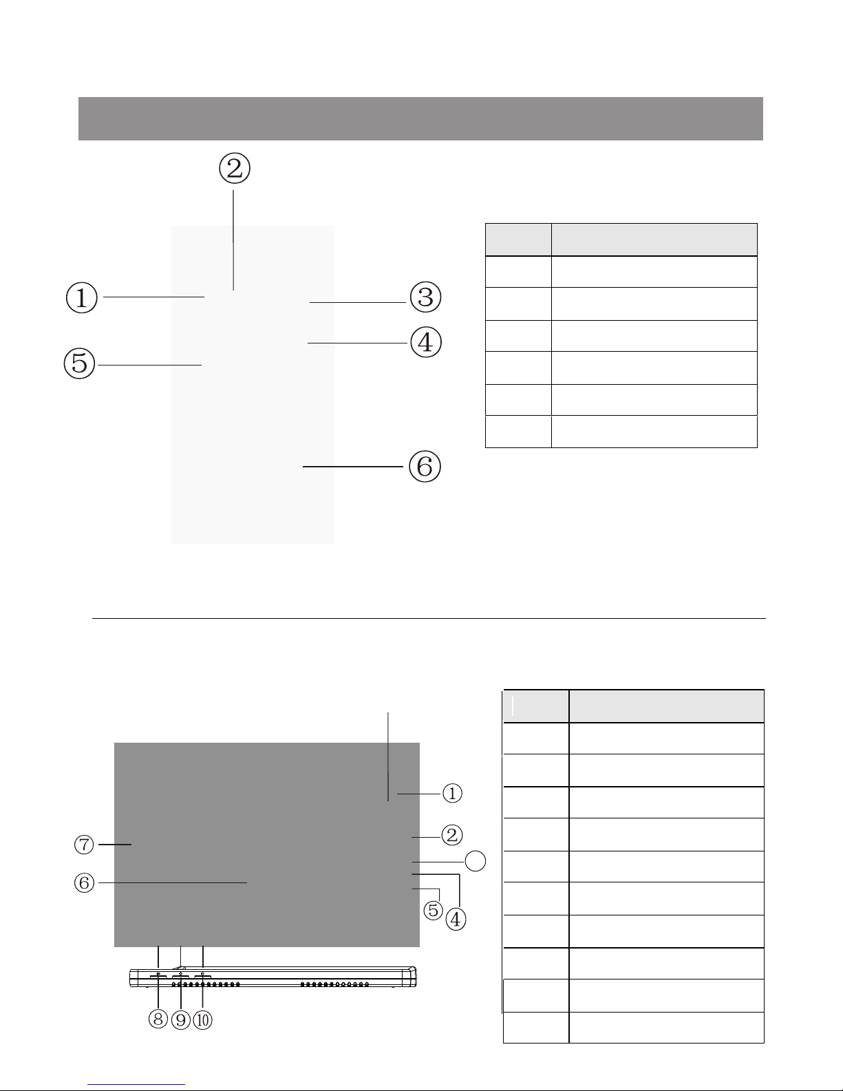
1. Parts and Functions.............................................................................................. 1
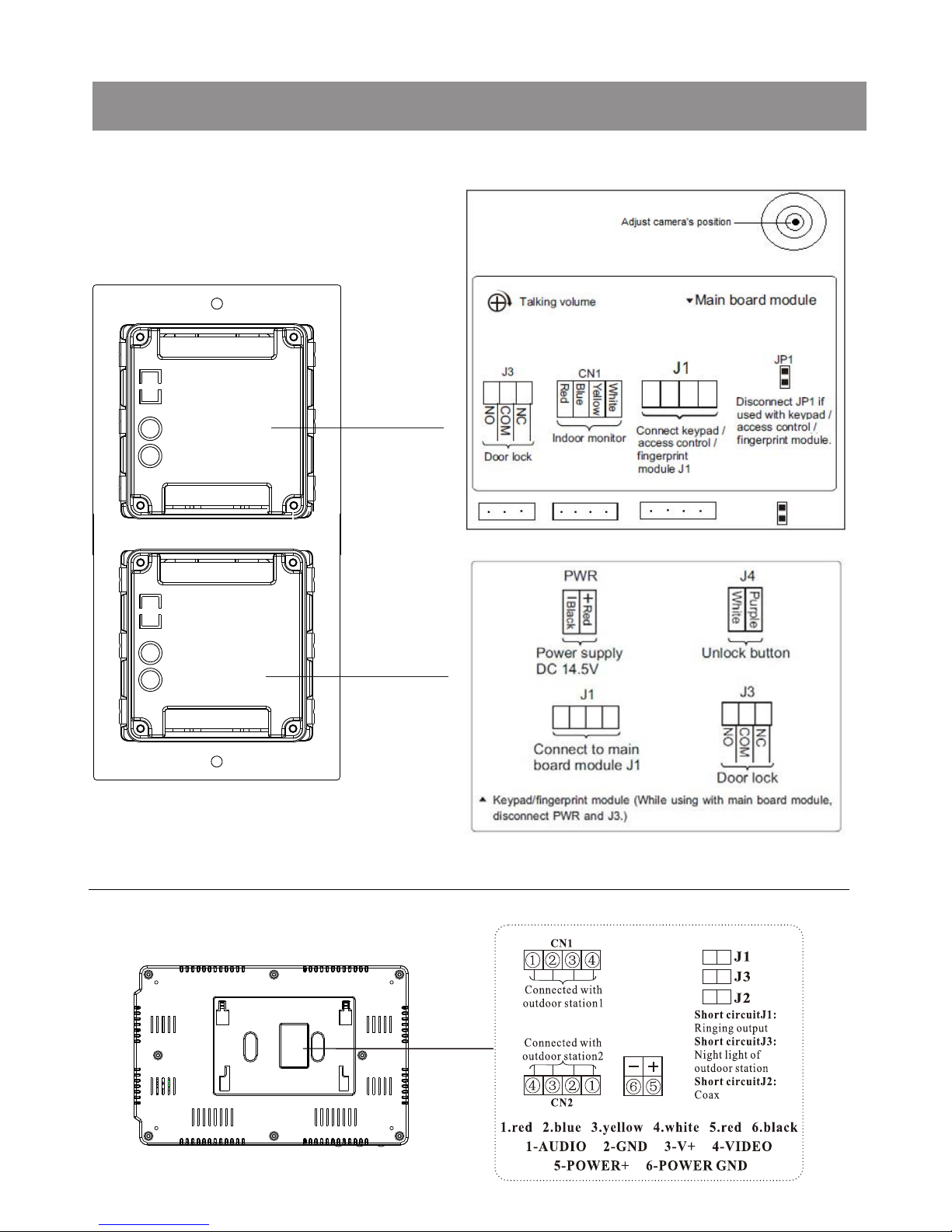
2. Terminal Descriptions .......................................................................................... 2
3. Specifications....................................................................................................... 3
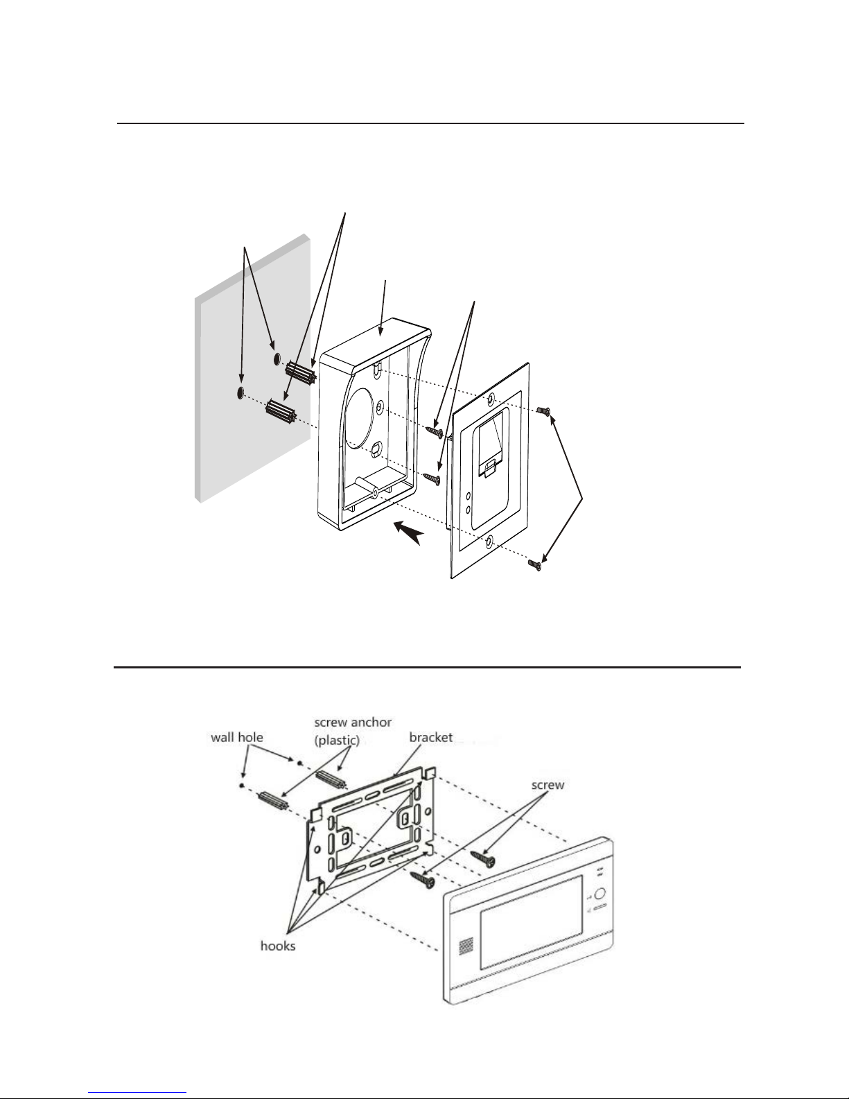
4. Mounting ............................................................................................................... 3
5. System Wiring and Connections ......................................................................... 5
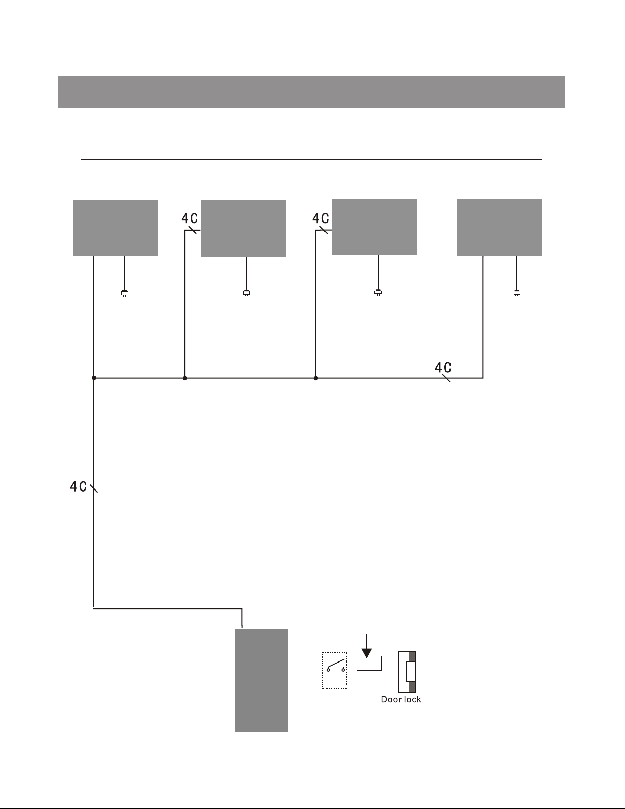
5.1 SVT-4 System with one entrance .................................................................... 5
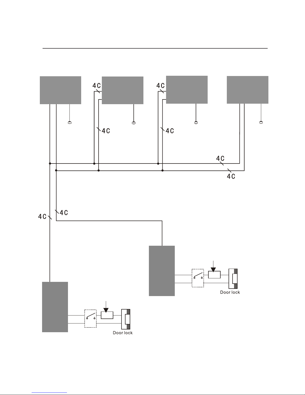
5.2 SVT-4 System with two entrances .................................................................. 6
6. Cable Requirements ........................................................................................... 10
7. User Instructions . ............................................................................................... 11
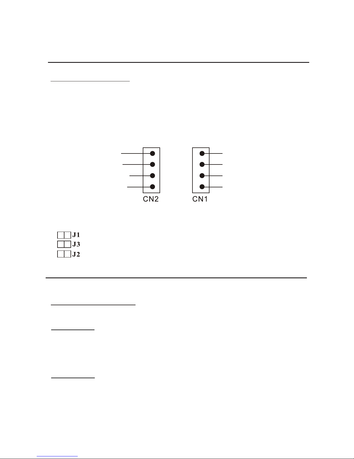
5.3 SVT-4 Wiring Connection .............................................................................. 7
7.1 Visitor calls .................................................................................................... 11
7.2 Monitor .......................................................................................................... 12
7.3 Intercom ........................................................................................................ 13
4.1 Mounting without the Rain Guard..................................................................... 3
4.2 Mounting with the Rain Guard..........................................................................4
4.3 Mounting the Indoor Monitor............................................................................ 4
5.3.1 Indoor Station........................................................................................... 7
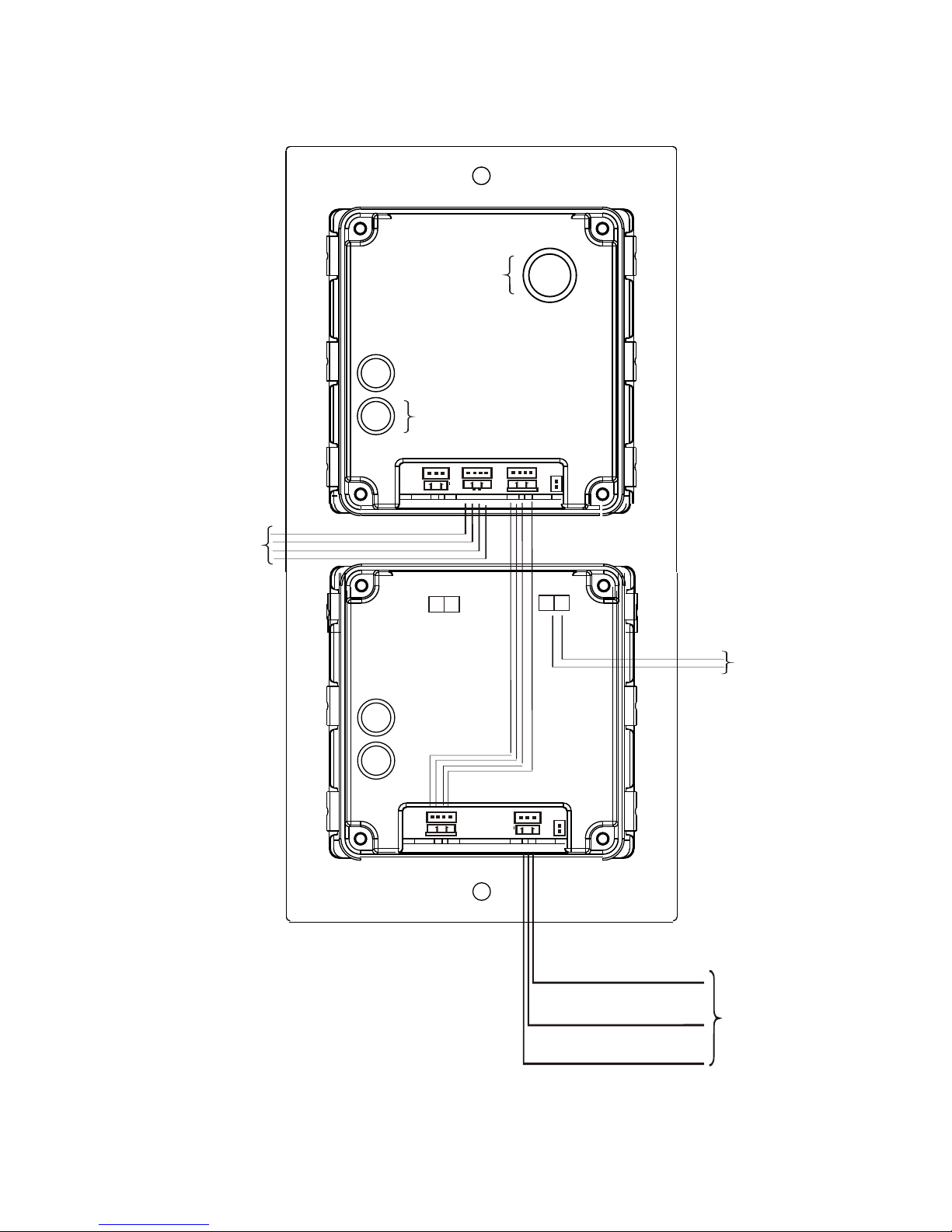
5.3.2 Outdoor Station........................................................................................ 7-8
8.How to set up User Codes ................................................................................. 14-15
5.3.3 Electric door lock connection ................................................................... 9

-1-
1.Parts and Functions
3
# Description
1
2
LED lights
3
High resolution camera
4
Built-in speaker
5
Call button
Built-in microphone
# Description
1 Built-in microphone
2 Monitor button
3 Intercom button
4 Door unlock button
5 Talk button
6 TFT 7” color display
7 Built-in speaker
8 Talking/Ring volume
9 Brightness
10 Contrast
Status light.
Calling in: red light
Monitoring/Talking: blue light
6Keypad

-2-
2.Terminal Descriptions

-3-
160-165 cm
1 2
4.Mounting
Hatch
Install into the wall
Screw hole
Screws
(fix with button
case)
3.Specifications
OUTDOOR STATION
Voltage: DC 14.5V
NO/NC: Max. 14.5V, 120mA
Lock Power Supply: Must be used according to lock.
Unlocking time: 01 - 99 seconds
Communication duration: 120s.
Communication transmission: 2-way communication
Working temperature: -4°F to 131°F / -20°C to +55°C
INDOOR MONITOR
Voltage: DC 14.5V
Communication duration: 120s.
Communication transmission: 2-way communication
Working temperature: 14°F to 131°F / -10°C to 55°C
4.1. MOUNTING WITHOUT THE RAIN GUARD

-4-
Screw anchors
Screws
Screws
(fix with rain cover)
Rain cover
Wall hole
4.2. MOUNTING WITH THE RAIN GUARD
4.3. MOUNTING THE INDOOR MONITOR

-5-
5.1. SVT-4 SYSTEM WITH ONE ENTRANCE
System Wiring and Connections5.
Outdoor
station 1
Power supply
for lock

-6-
5.2. SVT-4 SYSTEM WITH TWO ENTRANCES
Outdoor
station 1
Outdoor
station 2
Power supply
for lock
Power supply
for lock

-7-
5.3. SVT-4 WIRING CONNECTION
1. Red 2. Blue 3. Yellow 4. White
4-Video
1-Audio 2-GND 3-V+
5.3.1 Indoor Monitor
1. Red
2. Blue
3. Yellow
4. White
1. Red
2. Blue
3. Yellow
4. White
NOTE: Do not remove any of the jumpers from the back of the indoor
monitors.
By removing a jumper or changing its position, some of the features may
not work properly.
5.3.2 Outdoor Station
Upper module:
CN1: Use this port to connect indoor monitors.
J1: Must remain connected to J1 port on the lower module.
Lower module:
J1: Must remain connected to J1 port on the upper module.
J3: Use this port to connect a door lock.
The door lock is limited to 14.5V, 120mA.
Must use an additional power supply for the door lock. Ensure the power supply is
compatible with the door lock specifications.
J4: Exit button connection port.

-8-
NC
COM
NO
Door Lock
To Indoor Monitor
Adjust Talking Volume
Exit Button
.
Adjust Camera Position

-9-
5.3.3 Electric Door Lock Connection
1. Use the port J3 of the lower module to connect a door lock.
2. The door lock is limited to 14.5V, 120mA.
3. Must use an additional power supply for the door lock. Ensure the power supply is
compatible with the door lock specifications.

6.Cable Requirements
B
A
Cable Usage A B
CAT5 cable (must solder the wires together to ensure a good connection).
Using different cables may affect the maximum distance the system can reach.
230 feet
70 meters
30 feet
10 meters
NOTE:
1. The system expands to a maximum of 2 outdoor stations and 4 indoor monitors.
2. Each indoor monitor requires its own power supply(14.5V, 1.3A)
3. We recommend soldering the wires together to ensure a good connection (Do not use
wire nuts).
-10-

-11-
Press the call button at anytime, the
indoor monitor will show the view
from the front door camera
automatically. Press talking
button to have communication
with the visitor by the front door.
The visitor image shown on
the monitor
7.1 Visitor calls
Check
After pressing the unlocked button,
the indoor monitor still displays
the image from the front door
camera.
End the call
Talk begins
Open the lock
The talk time is
up to 2 minutes
Press the TALK
button or hang-up the
handset
The visitor presses
the call button
on outdoor
station-1
Ring Ring
The visitor presses
the call button
on outdoor
station-2
7.User instructions

-12-
All indoor monitors
ring
During the conversation
between the outdoor
station and the indoor
monitor, press button on
the main indoor monitor.
The indoor monitor press
button again to end the
conversation.
Call transferring from main indoor monitor to extension indoor
monitor
Any indoor monitor
press button or pick
up the handset to talk
with the outdoor station.
Press twicePress once
The indicator light of
Door 1 is on.
The indicator light of
Door 2 is on.
End the monitor
Press the
monitor
button
Monitor outdoor
station 1
Monitor outdoor
station 2
Press the
talk button
Press the
talk button
Monitor the
outdoor station
Press the
monitor
button
7.2 Monitor

-13-
End the call
All indoor monitors
ring
Press the TALKPress the
TALKING button or
hang-upbutton or hang-
up the handsetthe handset
Talk begins
Any indoor monitor
presses button or pick up
the handset to talk.
7.3 Intercom
In the standby mode,
press intercom
button in any
indoor monitor
During the talking, any indoor
monitor presses the intercom
button

-14-
1. The original factory default programming
password is 1234.
2. In the programming mode, set 40 groups of
4-digit codes for door open.
Set programming code
1. Switch off the power, press * and hold, switch on the power. After
hearing a long sound, release *.
2. After the long sound stops, another sound is heard, now you can
enter the new 4-digit programming password.
3. After entering the new password, a "DI" sound can be heard for 5
times.
Enter to the programming mode
1. Press *, "DI" sound should be heard twice, and then enter
4-digit programming password, "DI" sound should be heard
three times with LED light flashing. It indicates entering to the
programming mode successfully.
2. Press * to exit the programming mode with "DI" sound in five
times.
Set unlocked time
Factory default setting is 5 seconds.
1. Enter to the programming mode first.
2. Enter code 00, and "DI" sound should be heard twice.
3. Enter the targeted unlocked time: 2 digits (01 - 99 seconds);
00 is not valid in this mode.
4. After "DI" sound is heard for three times, it will return to
programming mode.
5. Press * to exit the programming mode.
8.How to set up the user codes

-15-
Delete user passwords
1. Enter to the programming mode first.
2. Enter position 01 - 30.
3. Press # to delete the password stored in 01- 30.
4. After "DI" sound is heard for three times, return to the
programming mode.
Add user passwords
1. Enter to the programming mode first.
2. Enter position 01- 30 (31-40 can not set unlocked time as they
are normal open/closed).
3. Enter 4-digit password. If long "DI" sound is heard twice, it
indicates password stored fails, and this password exists
somewhere else. If "DI" sound is heard for three times, it
indicates password stored succeeds. Return to the
programming mode.
1. Enter to the programming mode first.
2. Press #. After "DI" sound is heard twice, press # again. Anther
"DI" sound is heard twice.
3. Then, press # for seven times, the system deletes all the setting.
The unlocked time changes to 1 second, and the programming
password does not change. After hearing "DI" sound for five
times, the system reset, and all the user passwords are deleted.
1. Enter to the programming mode first.
2. Press #. After "DI" sound is heard twice, then enter 4-digits
password for deletion.
3. After "DI" sound is heard for three times, it indicates the
password has been deleted and return to the programming mode.
Delete user passwords directly
Delete all settings


The design and specifications of this user manual can be changed without any notification to the user.
All copyright and interpretation rights are reserved to SVT Innovations Inc.
Table of contents
Other SVT innovations Intercom System manuals

SVT innovations
SVT innovations SVT-2 User manual

SVT innovations
SVT innovations SVT-2 User manual

SVT innovations
SVT innovations SVT-MF4 User manual

SVT innovations
SVT innovations SVT-MF2 User manual

SVT innovations
SVT innovations SVT-SMART 500 User manual

SVT innovations
SVT innovations SVT-2 Series User manual

SVT innovations
SVT innovations SVT-IP A User manual