MS-CRD-PTI-E
Rev 0 3-04-WEL
Industrial Pressure Transducers
User’s Manual
E Model
www.swagelok.com
■ General Information and Ratings . . . . . . . . . . . . . . 1
■Safety Instructions . . . . . . . . . . . . . . . . . . . . . . . . . 1
■ Mechanical Installation . . . . . . . . . . . . . . . . . . . . . . 1
■Electrical Installation . . . . . . . . . . . . . . . . . . . . . . . . 2
■Maintenance . . . . . . . . . . . . . . . . . . . . . . . . . . . . . 4
■Troubleshooting . . . . . . . . . . . . . . . . . . . . . . . . . . . . 4
Contents
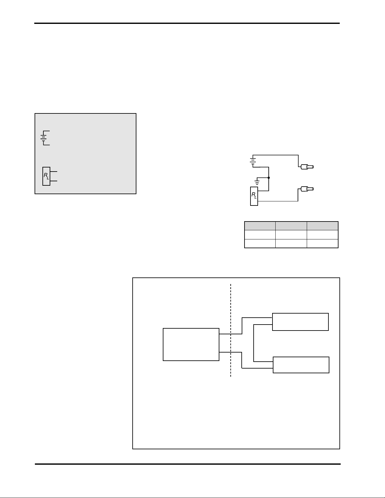
E Model
Use this hex only to
secure transducer while
installing electrical
conduit.
Mechanical Installation
Using the appropriate mating process connection, install the
transducer away from excessive heat and vibration whenev-
er possible. Be sure to install the system in accordance with
NEC requirements.
General information and Ratings
FM Approval Ratings
Explosion-proof
for Class I, Division 1, Groups A, B, C, D
Dust-ignition proof
for Class II and III, Division 1, Groups E, F, G
FM standards according to
FMRC 3600, 3615, and 3810
CSA Approval
CSA Standards according to CSA 25-1966, 30-M1986,
94-M91, and 142-M1987
Use this hex to install
the transducer process
connection
Safety Instructions
!For proper and safe operation, Swagelok E model
transducers must be installed, operated, and
serviced according to NEC, applicable local
regulations, and these instructions. Otherwise,
serious personal injuries, damage or both can
occur.
! Except for adjusting the length of the wires, the
electrical connection provided on the transducer
must be used as originally supplied and not
bypassed. Only qualified persons should work on
theses instruments.
! The shield / ground connection must be wired to
ground to protect the instrument from electromag-
netic disturbances.
! Do not exceed the overpressure rating.
Introduction
Swagelok®industrial pressure transducers allow for elec-
tronic monitoring of system pressures in a variety of indus-
trial applications. The E model transducer is specifically
designed to meet durability and performance demands of
industrial applications where explosion-proof ratings are
required.
50 N • m (36 ft • lb) max
®
Safe Product Use
Follow any enclosed instructions and refer to the product
catalog for detailed product information. When using a
transducer, the total system design must be considered to
ensure safe, trouble-free performance. Function, material
compatibility, adequate ratings, proper installation, oper-
ation, and maintenance are the responsibilities of the
system designer and user.