Swagelok PTX Series User manual

Intrinsically Safe
Pressure and Temperature
Transducers (PTX Series)
User’s Manual
This manual contains important information for the safe and
effective operation of the Swagelok®Intrinsically Safe Pressure
and Temperature Transducers, PTX series. Users must read and
understand its contents before operating the transducer.
www.swagelok.com

2Instrinsically Safe PTX User’s Manual
Contents
Safety . . . . . . . . . . . . . . . . . . . . . . . . . . . . . . . . . .2
Introduction. . . . . . . . . . . . . . . . . . . . . . . . . . . . . . 3
Product Information . . . . . . . . . . . . . . . . . . . . . . . . . 4
Specications . . . . . . . . . . . . . . . . . . . . . . . . . . . . 5
Control Drawing . . . . . . . . . . . . . . . . . . . . . . . . . . . .6
Installation . . . . . . . . . . . . . . . . . . . . . . . . . . . . . . 8
Mounting . . . . . . . . . . . . . . . . . . . . . . . . . . . . . . 8
Power Supply . . . . . . . . . . . . . . . . . . . . . . . . . . . 9
Interface Cable. . . . . . . . . . . . . . . . . . . . . . . . . . . 9
Setup . . . . . . . . . . . . . . . . . . . . . . . . . . . . . . . . . 11
Maintenance . . . . . . . . . . . . . . . . . . . . . . . . . . . . . 11
Troubleshooting . . . . . . . . . . . . . . . . . . . . . . . . . . . 12
Safety
Safety Summary
Read the entire safety information section and User’s Manual before using this product. Failure to do so
can result in serious injury or death.
Signal Words and Safety Alert Symbols Used in this Manual
WARNING Statements that indicate a hazardous situation which, if not avoided, could result in death or serious
injury.
CAUTION Statements that indicate a hazardous situation which, if not avoided, could result in minor or moderate
injury.
NOTICE Statements that indicate a hazardous situation which, if not avoided, could result in damage to the
equipment or other property.
Safety alert symbol indicating a potential personal injury hazard.
Safety alert symbol indictating a potential danger to life or of serious injuries due to catapulting parts.

Instriniscally Safe PTX User’s Manual 3
Safety Instructions
For proper and safe operation, Swagelok intrinsically safe PTX series transducers must be installed,
operated, and serviced according to applicable local regulations and these instructions. Otherwise,
serious personal injuries, damage or both can occur.
Except for adjusting the length of the wires, the electrical connection provided on the transducer must be
used as originally supplied and not bypassed. Only qualied persons should work on these instruments.
Do not exceed the overpressure rating.
Before servicing any installed pressure transducer you must
■ disconnect power
■ depressurize system
■purge the transducer
Residual material may be left in the transducer and system.
Introduction
The Swagelok Intrinsically Safe Pressure and Temperature Transducer (PTX) is an industrial pressure and temperature
transducer for monitoring uid pressure and temperature in automated uid systems using a MEMS pressure-sensing
technology. The PTX provides two analog outputs to monitor uid pressure and temperature in automated uid systems.
Each PTX communicates directly with the Swagelok Intrinsically Safe Intelligent Control Module™ (ICM™) unit through one
of the analog input connection ports on the ICM. Each PTX can also interface with traditional automation equipment with
suitable analog inputs such as Programmable Logic Controller (PLC), Distributed Control System (DCS), or Supervisory
Control and Data Acquisition (SCADA) system.
The PTX is available with a 1.5 in. Swagelok Modular Platform Component (MPC) surface mount in accordance with
ANSI/ISA 76.00.02 or with 1/4in.or 6 mm Swagelok tube tting end connections. It is UL®and ATEX certied for use in
hazardous areas.

4Instrinsically Safe PTX User’s Manual
Product Information
Fig. 1 PTX with MPC Modular Surface Mount
Front View
Sensor LED
Power LED
Network Connector
Plug
Mounting holes
PTX Enclosure
Screw
(2, other is opposite
one shown)
Fig. 2 PTX with Swagelok Tube Fitting
End Connections
Sensor LED
Power LED
Network Connector
Plug
PTX Enclosure
Screw
(2, other is opposite
one shown)

Instriniscally Safe PTX User’s Manual 5
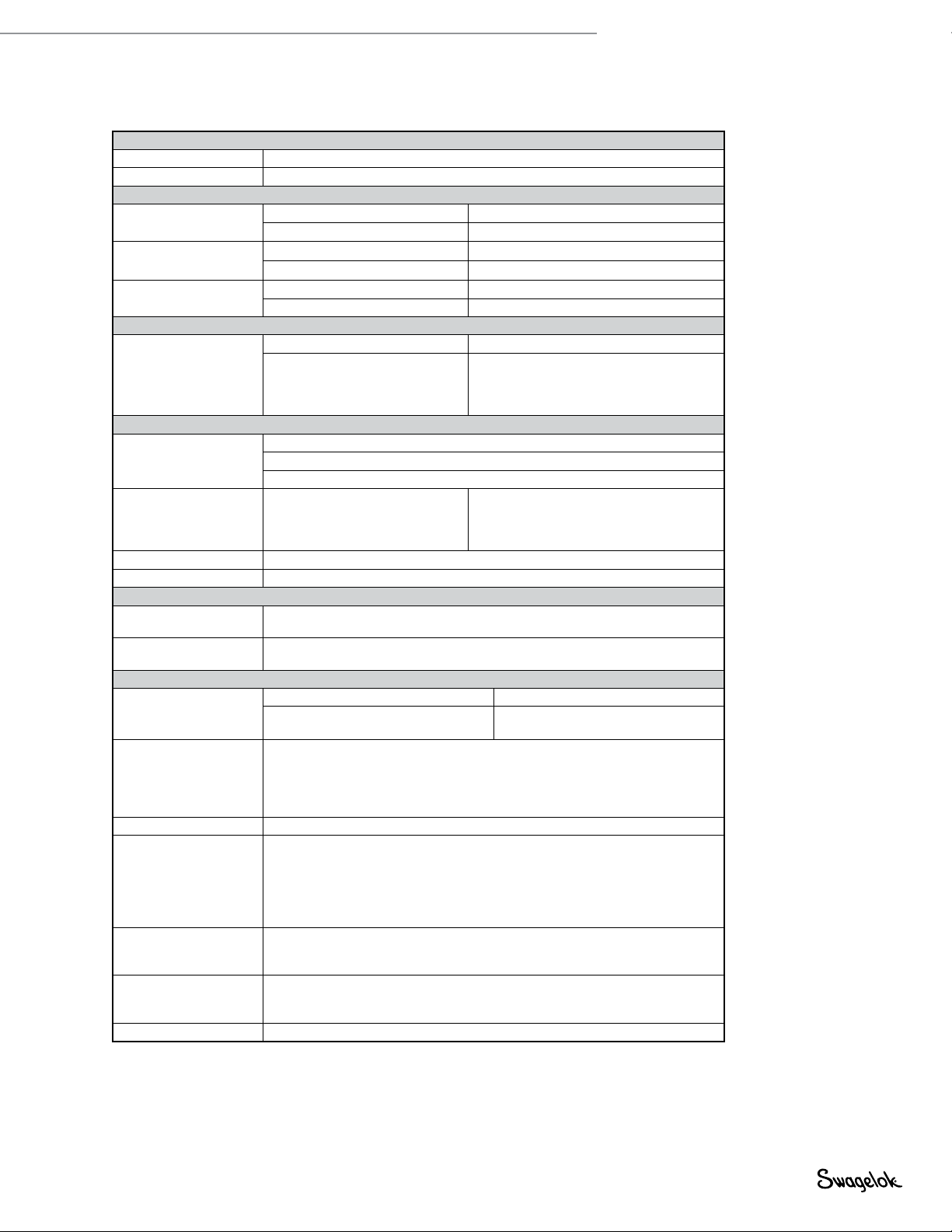
Specifications
Power
Voltage 9 to 28 V (dc), 24 V (dc), nominal
Current < 20 mA (dc) at 24 V (dc)
Temperature (environment)
Operating (Ambient) Minimum 23°F (–5°C)
Maximum 158°F (70°C)
Media Minimum 23°F (-5°C)
Maximum 158°F (70°C)
Storage Minimum -40°F (–40°C)
Maximum 158°F (70°C)
Temperature Measurement
Temperature
Measurement
Measurement Range 23 to 158°F (–5 to 70°C)
Accuracy, including:
Repeatability
Hysteresis
Nonlinearity
± 9°F (± 5°C absolute accuracy)
Pressure
Full-scale Range
0 to 50 psig (0 to 3.4 bar)
0 to 250 psig (0 to 17.2 bar)
0 to 500 psig (0 to 34.4 bar)
Pressure Measurement
Accuracy, including:
Repeatability
Hysteresis
Nonlinearity
± 2 % of full scale pressure of measurement
Overrange Pressure 2 × full scale
Burst Pressure 5 × full scale
Output Reading to Voltage Conversion
Temperature -40°F (-40°C) = 0.5 V (dc)
158°F (70°C) = 4.5 V (dc)
Pressure 0 psig = 0.5 V (dc)
full scale = 4.5 V (dc)
Miscellaneous Data
Weight
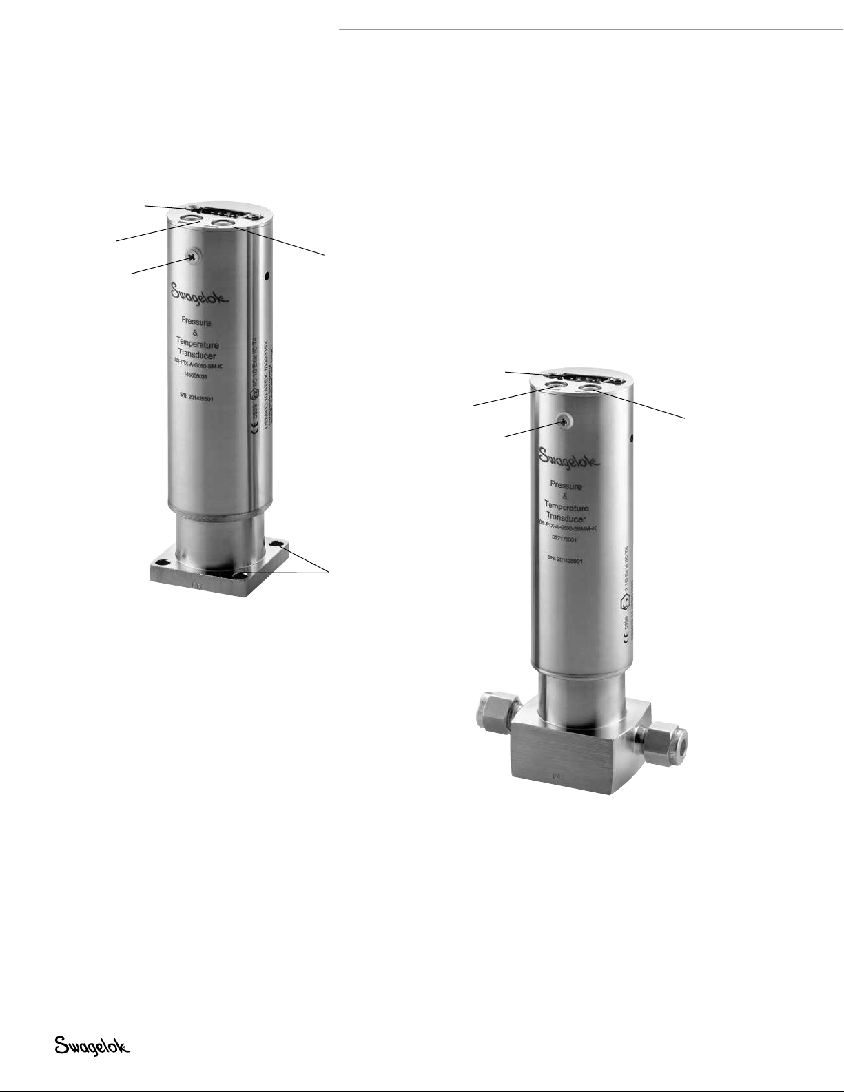
with MPC process connections 0.83 lb (375 g)
with 1/4 in. and 6 mm Swagelok tube
fitting end connections
1.27 lb (576 g)
Certifications
■ANSI/NFPA Class I, Division 1, Groups A, B, C, D, Temperature Class T4
■UL 913 - Edition 8, UL 60079-0 - Edition 6, UL 60079-11 - Edition 6
■cUL®- CSA C22.2 NO. 157-92 - Edition 3
■ATEX Standards: EN 60079-0, EN 60079-11
■ IEC: IEC 60079-0 - Edition 6, IEC 60079-11 - Edition 6
Ingress Protection IP64
Electromagnetic
Compatibility
EN 61326-1:2006
■RF Emissions: EN 55011
■ESD Immunity: EN 61000-4-2
■RF Immunity: EN 61000-4-3
■EFT Immunity: EN61000-4-4
■Conducted Immunity: EN 61000-4-6
Vibration
Tested to IEC 60068-2-6:2007
■ 10 to 150 Hz, at 2.04 g
■ 10 sweeps at 0.5 Octave/min
Shock
Tested to IEC 6068-2-27:1987
■ 50 g, 11 msec
■ 3 positive and 3 negative pulses each axis
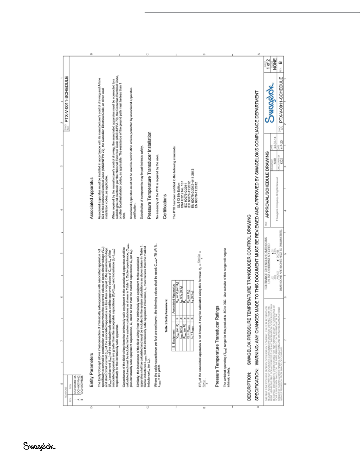
Entity Parameters See Control Drawing: PTX-V-0011-SCHEDULE
Note: Before installing the PTX in a hazardous location, review the control drawing on page 6.
This will help ensure all electrical connections to and from the PTX comply with safety requirements. For an
electronic copy of this manual, see www.swagelok.com.

6Instrinsically Safe PTX User’s Manual
Control Drawing
Fig. 3 PTX-V-0011-SCHEDULE

Instriniscally Safe PTX User’s Manual 7
Fig. 3 PTX-V-0011-SCHEDULE continued

8Instrinsically Safe PTX User’s Manual
Installation
Mounting
A PTX with 1/4 in. or 6 mm Swagelok tube tting process end connections should be installed in the system according to
Swagelok Tube Fitting Instructions for 1 in. (25 mm) and smaller ttings, MS-12-01. Mounting holes are provided on the
bottom of the PTX body. See below for dimension information.
A PTX with a 1.5 in. Swagelok MPC modular surface mount should be installed in the system according to the surface
mount assembly instructions in the MPC Series Modular Platform Components Assembly and Service Instructions,
MS-12-39.
Dimensions, in inches (millimeters), are for reference only and subject to change.
NOTICE Removal of the PTX enclosure screws will void the product warranty, damage the Ingress
Protection rating, and negate the intrinsically safe hazardous location rating of the PTX.
Fig. 4 Product Dimensions
Analog input
connector (male DB9)
0.59
(15.0)
1.50
(38.2)
Four
mounting
holes,
0.21 (5.3)
dia
1.50
(38.2)
Front FrontBottom
Top
Top
MPC Modular Surface Mount Swagelok Tube Fitting End Connections
5.85
(149)
2.54
(64.5)
1.49
(37.8)
5.27
(134)
0.25
(0.64)
Analog input
connector (male DB9)
2×
1.625 (41.3) dia
Four tapped
mounting holes,
#10-32 UNF-2C
46°
44° Hole depth:
0.25 (6.4) min
0.43 (10.9) max
Bottom
PTX Enclosure
Screw
(2, other is opposite
one shown, also on
MPC modular surface
mount product)

Instriniscally Safe PTX User’s Manual 9
Power Supply
The instrinsically safe PTX can be used with any power supply capable of providing between 9 and 28 V (dc) and 50 mA per
PTX in use. Supplying less than 9 V (dc) to the transducer will result in inaccurate measurements.
NOTICE Supplying more than 28 V (dc) can result in damage to the transducer.
Hazardous Location Power Supply
When used in hazardous locations, a properly rated power supply must be used. The intrinsically safe PTX can be powered
by any power supply identied as an intrinsically safe associated apparatus with output parameters of Voc ≤ 28 V (dc) and
Isc ≤ 1 A.
WARNING
A voltage higher than 28 V (dc) is outside the product’s safety rating. Using a voltage outside the safety
rating could result in an explosion.
Interface Cable
Cable Length
In non-hazardous locations, cable length is limited by the voltage drop for the power supply and the added noise on the
pressure and temperature signal lines. It is recommended that transducer cables not exceed 100 ft (30.4 m) in length in
order to minimize these effects.
Hazardous Location Cable Length
The wire length between intrinsically safe equipment and associated apparatuses is determined by the interaction of the
device entity parameters, as described in the following table. The parameter symbols and subscripts are dened in ATEX
standards EN60079-0 and EN 60079-11.
Parameter Intrinsically Safe
Equipment
Must Be Associated Apparatus
(ex. power source)
Voltage Vmax (or Ui) ≥ Voc (or Vtor Uo)
Current Imax (or Ii) ≥ Isc (or Itor lo)
Power Pmax (or Pi) ≥ Po
Capacitance Ci+ Ccable ≤ Ca(or Co)
Inductance Li+ Lcable ≤ La(or Lo)
The cable between the two devices has a capacitance and inductance that must be added to that of the intrinsically safe
equipment parameter. Once the entity parameters of the devices are known the maximum cable length can be calculated.
Where available, the manufacturer’s specication for the cable’s capacitance and inductance can be used. When the cable
capacitance and inductance per foot are not known the following values must be used:
• Ccable= 70 pF/ft
• Lcable = 0.2 μH/ft
The ATEX standards dene additional safety factor rules that can apply when determining the maximum cable length.
These do not apply in this case because the PTX has a capacitance (Ci) and inductance (Li) of zero.

10 Instrinsically Safe PTX User’s Manual
Example
Here is an example of using these parameters to determine the cable length.
1. Construct the entity parameter table for the known values:
Intrinsically Safe Equipment
(Swagelok PTX)
Associated Apparatus
(Power Supply)
Vmax 28 V ≥9.5 V Voc
Imax 1A ≥ 1A Isc
Pmax - ≥ - Po
Ci+ Ccable 0 µF + Ccable ≤0.5 μF Ca
Li+ Lcable 0 µH + Lcable ≤8 μH La
The entity parameters Pmax and Pocan be ignored if the voltage and current parameters are compatible.
2. Calculate the maximum allowable cable capacitance and inductance.
Ccable,max = 0.5 µF − 0 µF = 0.5 µF
Lcable,max = 8 µH − 0 H=8 µH
3. Calculate the maximum cable lengths using the maximum allowable capacitance and inductance.
Length related to maximum capacitance = Ccable,max / Ccable/length =0.5 µF / 70 pF/ft = 7143 ft (2177 m)
Length related to maximum inductance = Lcable,max / Lcable/length = 8 µH / 0.2 µH/ft = 40 ft (12.1 m)
The entity parameters will vary from one piece of apparatus to the next so the calculation must be done for each piece of
apparatus in use.
Cable Bend Radius
The cable bend radius will vary according to the cable manufacturer’s recommendations. A bend radius of 6 to 10 times the
diameter of the cable is typical.
Wiring Diagram
The cables for the intrinsically safe PTX should be wired in accordance with Article 504 of the National Electrical Code
(ANSI/NFPA 70). The connector for the PTX is a standard male DB-9. The cable will be a socket DB-9 with the pinout as
described below.
Temperature Output
Power Input
GND
Pressure Output
1
2
3
4
5
6
7
8
9
Fig. 5 Wiring Diagram

Instriniscally Safe PTX User’s Manual 11
It is recommended the parameter measurement wires have their own connection to ground. A cable with three shielded,
twisted pair is optimal to achieve this, as shown in Figure 6. This will ensure that the voltage drop which occurs with the
ow of the operating current across the cable does not distort the temperature and pressure measurements.
Setup
1. Install the PTX into your system, see Mounting.
2. Connect the interface cable to the PTX and the network device.
V+
V-
Pin 3
Pin 2
Pressure + Pin 8
Pin 6
Pressure -
Temperature + Pin 9
Pin 7
Temperature -
Fig. 6 Parameter Measurement Wire

Maintenance
Additional assembly hardware for the MPC surface mount is available. Refer to Modular Platform Components (MPC),
MS-02-185, for ordering information.
There are no eld-maintainable parts within the intrinsically safe PTX. Contact your authorized Swagelok representative for
assistance.
NOTICE Removal of the PTX enclosure screws will void the product warranty, damage the Ingress
Protection rating, and negate the intrinsically safe hazardous location rating of the PTX.
Troubleshooting
Problem Possible Cause Remedy
Power LED
Off No power applied to the device. Connect power.
Green Normal operation. No action needed.
Sensor LED
Off
If the Power LED is also OFF, indicates no power
applied to the device. Connect power.
If the Power LED is on, indicates sensor element
failure. Replace PTX unit.
Green Normal operation. No action needed.
General
Output signal
unchanged after
change in pressure
Mechanical overload through overpressure Replace PTX unit.
Signal value too
small Diaphragm is damaged, e.g. through impact. Replace PTX unit.
Signal value
dropping off / too
smalll
Abrasive/aggressive media; corrosion of diaphragm/
pressure connector; transmission fluid missing Replace PTX unit.
Signal value erratic
Electromagnetic interference source in the vicinity Shield the transducer and the cables. Remove the
interference source.
Working temperature too high / too low Ensure temperatures within range of the transducer
(see Specifications).
Signal value
incorrect Working temperature too high / too low Ensure temperatures within range of the transducer
(see Specifications).
No output signal
Cable break Check connections and cable.
Incorrect wiring or supply voltage Check wiring and supply voltage.
Contact your authorized Swagelok representative for additional assistance.
Swagelok, ICM—TM Swagelok Company
UL, cUL—TM UL LLC
© 2015-2020 Swagelok Company
MS-13-229, RevB, May 2020
Warranty Information
Swagelok products are backed by The Swagelok Limited
Lifetime Warranty. For a copy, visit swagelok.com or contact
your authorized Swagelok representative.
Each product catalog and user manual
is up to date at the time of printing;
subsequent revisions to individual product
catalogs and user manuals will be posted
to www.swagelok.com and will supersede
the printed version.
Table of contents
Other Swagelok Transducer manuals
Popular Transducer manuals by other brands

Iskra
Iskra MT416 user manual

DATUM ELECTRONICS
DATUM ELECTRONICS M425 Handbook & installation guide

MKS
MKS UniMag 971B Operation and installation manual

GREISINGER
GREISINGER GPHU 014 MP operating manual

Garmin
Garmin gWind Wireless 2 installation instructions

Ashcroft
Ashcroft GC30 Installation and maintenance instructions