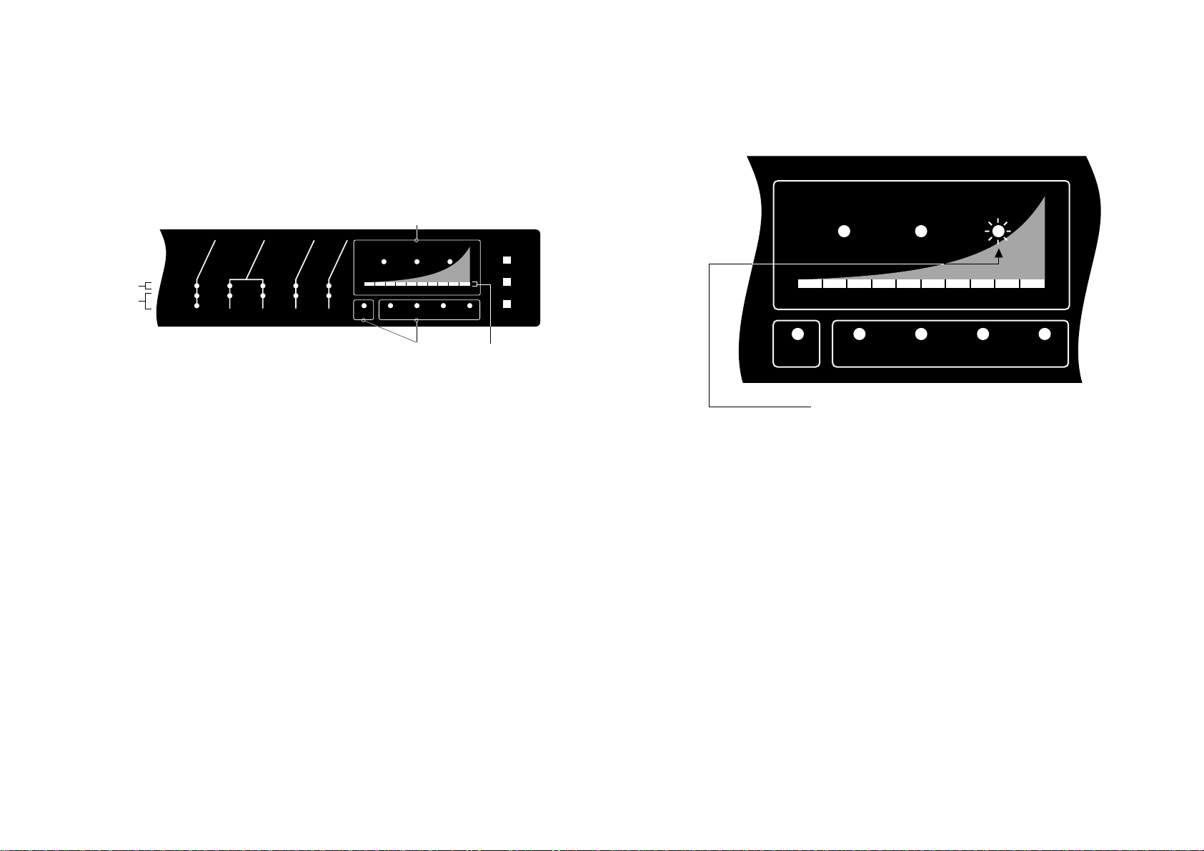
AirSense STRATOS HSSD User manual

Iss. 1-6/98
Master Stratos™ Protects:
Slave Detector 2 Protects:
Slave Detector 3 Protects:
Slave Detector 4 Protects:
Your Protected Areas are:
Your Fire Officer is:
Your Area/location is:
Your Emergency/assembly area is:
In line with continuous product improvement we reserve the right
to modify or update specifications without notice.
This guide outlines basic detector displays and
gives a brief indication of what to do when
the lamps illuminate.
This is not a full technical or installers manual.
Equipment may vary according to specification.
If there is any doubt please contact your supplier.
Ref. 0B4A3.AY
AirSense Technology Limited
1 Oak House • Knowl Piece • Wilbury Way • Hitchin • Hertfordshire SG4 0TY • UK
Tel: (+44) (0)1462 440666 • Fax: (+44) (0)1462 440888
e-mail: [email protected]
AirSense Technology Benelux BV
Graaf Florisweg 52, 2805 AM Gouda • Nederland
Tel: (+31) 1825 17078 • Fax: (+31) 1825 18771
e-mail: [email protected]
AirSense Technology (Aust) Pty Ltd
122 Ashley Street • Underdale • S.A. 5032
P.O. Box 302 • Torrensville Plaza • S.A. 5031
Tel: (08) 8234 2525 • Fax: (08) 8443 9625
e-mail: [email protected]

What do the lights mean?
ISOLATE
TEST
RESET
SMOKE DENSITY
AUX
FIRE
PRE-
ALARM
RENEW
OK
FAULT
OK
ISOL.
ON
FAULT
OK
HIGH
OK
LOW 1234
Ref.
Air Flow
12345678910
Detector
Power
Separator
SLAVE DETECTORSMASTER
Top line (Green)
Below (Yellow)
Master & Slaves
(Yellow) Bar Graph
(Yellow)
Alarm Levels (Red)
ThisdisplayislocatedontheStratos-HSSD®Masterunit(andremotemimic
if fitted). Its purpose is to indicate the condition of the Master and Slave
detector units connected to the Master detector. If Slave detectors are
installed, the detector/area being given on the display is indicated by a
flashingYellowlightbelowthebargraph,(thislightwillflashfortenseconds
per detectorbeing indicated).During theinterrogation/display timeit will
show the condition of Air Flow, Detector, Power, Dust Separator and any
alarms within the area of its protection.
TheAirFlow,Detector,PowerandSeparatorshouldallhavetheirrespective
Greenlightson.IfaGreenlightextinguishes,ayellowlightwillcomeonand
afaultcondition will begenerated. This faultcondition should normallybe
transmittedtotheFireAlarmIndicatorPanelandapre-selected routinewill
automatically be carried out.
It is important to understand that if any of the yellow Fault lamps are
illuminated,thentheareainquestionmaynotbeprotectedbytheStratos®
system.
This alarm level is fixed at bargraph level 8. If the red FIRE light operates,
thissignalshouldalwaysbetransmittedtotheFireIndicatorPanel.Itisnow
usually time to commence evacuation procedures. Other actions in the
event of the FIRE lamp operating will depend upon the application, but
typically it would involve; power down of equipment, calling Fire Brigade
and input to first leg of automatic Fire Extinguishing systems. Follow
instructions given to you by your Fire Warden. Act strictly in accordance
with the Emergency Plan for your building or area.
As with the PRE-ALARM level, if no obvious smoke is present in the area, it
maybeusefultoverifyifthebargraphisstillilluminatedfortheareainwhich
thealarmisgenerated.Iftheyellowbargraphisnolongerilluminateditmay
mean that it was a transient burst of smoke which is no longer present. If
it remains illuminated, then it is likely that an incipient fire is present in the
area, or an unusual smoke producing process is taking place.
Extra audible or visual alarms will normally be sounding within the area
whichare drivenfrom tothe controllingFire IndicatorPanel. Urgentaction
is necessary.
NOTE - Because the Stratos®system is capable of detecting extremely low
levels of smoke, The staged alarm facility may be configured so that
increasing levels of alarm can signal an increasing degree of danger.
SMOKE DENSITY
AUX
FIRE
PRE-
ALARM
1234
Ref.
12345678910
SLAVE DETECTORSMASTER
The red FIRE lamp is illuminated
What to do if...

SMOKE DENSITY
This ten segment bargraph shows the current smoke density sensed by the system. This
bargraph also displays other information during the TEST routine (see below) and it gives
a 'rolling' single segment display during the fifteen minute duration Fastlearn™ routine.
Thered AUX, PRE-ALARM & ALARM LED,s will operate whenthebargraphdisplay reaches
the pre-set levels at which the output relays operate.
The TEST routine establishes the settings programmed into the detector by operating
various LED's in sequence. These settings include; The position of the alarms in relation to
the Bargraph, the duration of the Delays and the present sensitivity of the detector being
tested.
PUSH BUTTONS
(only operational when enabled at programmable functions 35, 36 and 37)
RESET- This button resets any latched Alarm or Fault relays. It also takes the unit out of
programming mode.
TEST- This button performs a self test on the currently indicated detector as shown on the
'SLAVEDETECTORS'displayand shows;AlarmLevels,TimeDelaysandDetectorSensitivity.
ISOLATE-Thisbuttonputsthedetectorbeingindicatedonthe'SLAVEDETECTORS'display
off-line,wherebyit is notcapableofgeneratingany alarms orfaults.Ifoperated,afault relay
outputwill begenerated,which will normallycause a Faultconditionto beindicatedon the
host Fire Indicator Panel.
Operationofanyoftheabovebuttonsarerecordedasseparateentriesinthedetectorsevent log.
Entries in this log are shown with time and date of occurrence. The event log can be printed to
a serial printer via Function 45 or shown on Screen via an IBM compatible PC and then printed
to the PC's printer. The Event Log is capable of storing approx. 100 entries, and when it is full it
over-writes the oldest event in the buffer.
ISOLATE
TEST
RESET
SMOKE DENSITY
AUX
FIRE
PRE-
ALARM
RENEW
OK
FAULT
OK
ISOL.
ON
FAULT
OK
HIGH
OK
LOW 1234
Ref.
Air Flow
12345678910
Detector
Power
Separator
SLAVE DETECTORSMASTER
Operational Indicators Detector Indicators Push Buttons
Alarm Levels
Controls & Indicators
DETECTOR INDICATORS
Air Flow
Green OK LED Steady Normal operation, airflow within limits.
Green OK LED Flashing Detector setting up airflow limits.
Yellow HIGH LED Steady Airflow high, pipe may be broken
Yellow LOW LED Steady Airflow low, pipe may be blocked or aspirator faulty
Detector
Green OK LED Steady Normal operation of the detector chamber
Yellow FAULT LED Flashing Slave loop error rate high, check Slave comms. cable.
Yellow FAULT LED Steady Detector head fault or process error has occurred.
Green ON LED Steady Normal operation
Yellow ISOL LED Steady Detector is isolated, not capable of generating alarms
Green ON LED Flashing Is operating in Demonstration mode.
Power
Green OK LED Steady Normal operation
Yellow FAULT LED Flashing Battery fault.
Yellow FAULT LED Steady Mains fault
Separator
Green OK LED Steady Normal operation
Yellow RENEW LED Flashing Dust Separator removed
Yellow RENEW LED Steady Dust Separator needs replacing

What to do if...
SMOKE DENSITY
AUX
FIRE
PRE-
ALARM
1234
Ref.
12345678910
SLAVE DETECTORSMASTER
The Red AUX lamp is illuminated
The AUX alarm may be programmed to operate between bargraph level 2
to10.It is analarm which maybe set togive a 'pre'pre-alarm, alternatively
it may be used as a post FIRE warning indicator. Actions in the event of an
AUX alarm will therefore vary according to the programmed setting of the
AUX alarm in the protected area.
SMOKE DENSITY
AUX
FIRE
PRE-
ALARM
1234
Ref.
12345678910
SLAVE DETECTORSMASTER
The red PRE-ALARM lamp is illuminated
What to do if...
This alarm level can be programmed to operate between bargraph levels 4
to 8. If the red PRE-ALARM light operates, this signal will often be
transmittedtotheFireIndicatorPanel.ActionsintheeventofthePre-Alarm
operating will depend upon the application, but typically it will involve
summoning assistance to find the source of smoke. (see note)
It will be useful to verify if the bargraph is still illuminated for the area in
whichthealarmisgenerated.Iftheyellowbargraphisnolongerilluminated
itmaymeanthatitwasatransientburstofsmokewhichisnolongerpresent.
Ifitremainsilluminated,thenitislikelythatan incipientfireispresentinthe
area, or an unusual smoke producing process is taking place.
Extra audible or visual alarms may now be sounding which are connected
to the Fire Indicator Panel. Urgent action is necessary.
You should contact your Supervisor or Floor Fire Warden immediately,
informing them of the problem.
NOTE-BecausetheStratos®systemiscapableofdetectingextremelylowlevels
of smoke, an alarm condition need not mean that the area needs to be
immediately evacuated. The staged alarm facility may be configured so that
increasing levels of alarm can signal an increasing degree of danger.
The AUX alarm is:- USED/UNUSED
The AUX alarm is set at level No:- 2 3 4 5 6 7 8 9 10
(Circle appropriate number)
The AUX alarm is used to:-
Other AirSense Smoke Alarm manuals
Popular Smoke Alarm manuals by other brands

Ei Electronics
Ei Electronics Ei161e instruction manual

System Sensor
System Sensor BEAM1224SA Installation and maintenance instructions

Det-Tronics
Det-Tronics X3300 instructions

SB
SB SB-SK540 quick start guide

System Sensor
System Sensor Innovair DH100ACDCLPX Installation and maintenance instructions

Emerald Planet
Emerald Planet EP-RF-Li10 user manual

ADEMCO
ADEMCO 4192CPM Installation and maintenance instructions

Interlogix
Interlogix 60-460-95/NX-495 installation instructions

olympia electronics
olympia electronics BSR-6055 quick start guide

Chiptech
Chiptech 130809 installation instructions

Kidde
Kidde KN-COSM-B features and benefits

Kidde
Kidde P4010ACS-WCA user guide