GB/DE.TBLZ193.230201
www.swegon.com 3
Änderungsrechte vorbehalten
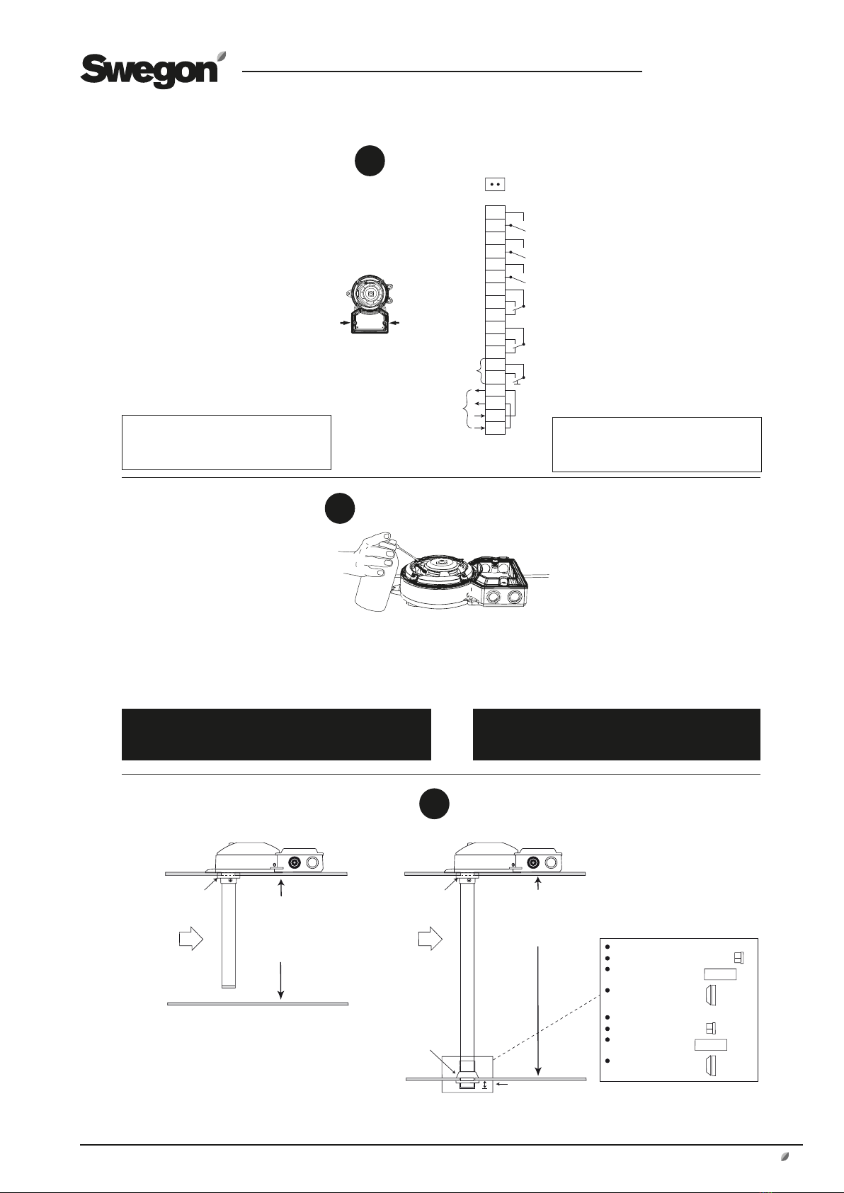
Contamination
Verschmutzung
Jumper ON disables
air flow monitoring.
Ein aufmontierter Bügel inaktiviert
die Luftduchflussüberwachung.
Air flow alarm
Luftstromalarm
Failure
Systemstörung
Smoke alarm
Rauchalarm
Smoke alarm
Rauchalarm
Test/Reset
Do not apply any voltage on terminal 5 and 6!
Keine Spannung an Klemme 5 und 6 verwenden!
Power supply
Spannungsversorgung
The relay outputs are shown in power off/alarm condition.
Die Relaisausgänge werden im ausgeschalteten Alarm-
Modus angezeigt.
6
7A
8A
3
4
5
1
2
9A
7B
8B
9B
10
11
12
13
14
15
5
Rauchmelder-Test.
7
Überprüfen Sie den Rauchmelder mit dem
Rauchmelder-Tester SOLO A5.
• Entfernen Sie den Stopfen der
”Testöffnung” und geben einen Sprühstoß
des Aerosolsprays hinein.
Bei einer Alarmierung leuchtet die
rote LED auf der Leiterplatte und am
Rauchmelder. Bei einem Servicealarm
leuchtet die gelbe LED auf der
Leiterplatte und die grüne LED am
Rauchmelder.
• WICHTIG:
Schließen Sie die Testöffnung wieder
mit dem Stopfen.
Check the detector with smoke detector
tester SOLO A5.
• Move the "test hole plug" to the side and
briefly release a spray of aerosol.
When alarming the LED lits red on the
detector and when service alarming
(contamination) it lits green.
• IMPORTANT!
Reassemble the "test hole plug".
Do not drill any holes in the cover for signs etc.
Holes will cause air leakages and seriously disturbe the
function of the detector.
Test of detector.
Anschließen von Rohren in Kanälen mit
unterschiedlichen Durchmessern.
Drill a hole
Ø 51 mm.
NOTE!
Diameter of the duct bigger than 0,6 m.
The venturi pipe should penetrate the whole duct.
Max diameter of the duct 0,6 m.
Use the venturi pipe 0,6 m.
Shorten the pipe, if necessary.
For ducts with a ø of less than 0,6 m use the 0,6 m pipe, standard.
For ducts with a ø of between 0,6 m and 1,4 m use the 1,5 m pipe.
For ducts which are larger than 1,4 m use the 2,8 m pipe.
Bohren Sie
ein Loch mit
Ø 51 mm.
HINWEIS:
Durchmesser größer als 0,6 m:
Das Venturirohr sollte den gesamten Kanal durchdringen.
Bohren Sie ein Loch
mit Ø 38 mm.
Drill a hole Ø 38 mm.
Bohren Sie ein Loch
mit Ø 38 mm.
Drill a hole Ø 38 mm.
Max. Durchmesser des Kanals: 0,6 m.
Verwenden Sie das Venturirohr 0,6 m.
Kürzen Sie das Rohr bei Bedarf.
Für Kanäle mit einem ø kleiner als 0,6 m verwenden Sie das Rohr 0,6 m.
Für Kanäle mit einem ø zwischen 0,6 m und 1,4 m verwenden Sie das
Rohr 1,5 m.
Für Kanäle mit einem größeren ø als 1,4 m verwenden Sie das Rohr 2,8 m.
Das Venturirohr darf nicht mehr als max.
30 mm durch die Kanalwand hindurch reichen.
The venturi pipe shall not protrude more
than max 30 mm through the duct wall.
Kürzen Sie das Rohr auf die richtige Länge.
Bringen Sie den Rohrverschluss an.
Setzen Sie die Kunststoff-
abschlussdichtung ein.
Setzen Sie die Gummi-
dichtung HFU204 ein.
Shorten the pipe to correct length.
Insert the end plug.
Put on the plastic end
gasket.
Put on the rubber
gasket, HFU204.
Fitting of pipes in ducts with different
diameters.
Elektroinstallation.
1. Lösen Sie die zwei Schrauben, um den Deckel
des elektrischen Anschlussgehäuses zu öffnen.
2. Uniguard Superflow verfügt über zwei
beigefügte Kabeldurchführungen für
Kabeldurchmesser von 8-13 mm.
3. Schließen Sie die Kabel gemäß Schaltplan an.
24 V AC/DC: UG-5-AFR-24V
UG-5-AFR-24V-MB
UG-5-AFR-24V-Z*
UG-5-AFR-24V-MB-Z*
230 V AC: UG-5-AFR-230V
UG-5-AFR-230V-MB
UG-5-AFR-230V-Z
UG-5-AFR-230V-MB-Z
Bei Modbus-Anschluss beachten Sie bitte
die entsprechenden Installationsanleitung.
Für vollständige technische Produktinformation
sehen Sie das Produktdatenblatt.
1. Remove the cover over the connection
housing (two screws).
2. Uniguard Superflow has 2 glands, for cable
diameter 8-13 mm, enclosed.
3. Connect the cables according to the wiring
diagram.
24 V AC/DC: UG-5-AFR-24V
UG-5-AFR-24V-MB
UG-5-AFR-24V-Z*
UG-5-AFR-24V-MB-Z*
230 V AC: UG-5-AFR-230V
UG-5-AFR-230V-MB
UG-5-AFR-230V-Z
UG-5-AFR-230V-MB-Z
For Modbus connection, see the instruction
enclosed with the product.
For complete technical product information, see
the product data sheet.
Electrical installation.
6
Bohren Sie keine Löcher für Schilder usw. in das Gehäuse.
Löcher führen zu Undichtigkeiten und Luftaustritt und beein-
trächtigen die Funktionsfähigkeit des Rauchmelders erheblich.
* WICHTIG: Um die Funktion sicherzustellen
soll das Steuergerät SM und ein Kabel mit
Metallmantel benutzt werden. Gilt nur für DIBt-
geprüfte 24 V Installationen in Deutschland.
* IMPORTANT: In order to ensure the function,
use control unit SM and metal-covered cables.
Applies only to DIBt-approved 24V installations
in Germany.