SWF Dual Function E Series User manual

MMEEEE--110011220011
USER ’’
S MANUAL
Dual Function Series Operating
SSuunnSSttaarr CCOO..,, LLTTDD..
•Dual Function 1x1
•Dual Function E-Series
•Dual DM Series
•Dual K Series


1. THIS IS AN INSTRUCTION FOR SAFE USE OF AUTOMATIC
EMBROIDERY MACHINES. READ THOROUGHLY BEFORE USE.
2. CONTENTS IN THIS INSTRUCTION MAY CHANGE, WITHOUT
PRIOR NOTICE, FOR IMPROVEMENT OF MACHINE QUALITY AND
THUS MAY NOT CORRESPOND TO THE MACHINE YOU
PURCHASED. CONTACT YOUR SALES AGENT FOR INQUIRIES.
3. THIS IS DESIGNED AND MANUFACTURED AS AN INDUSTRIAL
MACHINE. IT SHOULD NOT BE USED FOR OTHER THAN
INDUSTRIAL PURPOSE.

Table of Contents
1.0
Dual Function Series Embroidery Machine Operation Box
........................................................................ 1-1
1.1 Names and Functions .................................................................................................................................... 1-1
1.2 LCD monitor .................................................................................................................................................. 1-3
2.0
Basic Procedures of Embroidery
......................................................................................................................... 2-1
2.1 Power ON ....................................................................................................................................................... 2-1
2.2 Basic procedures ............................................................................................................................................ 2-5
3.0
Installing Machine Operating Program
.............................................................................................................. 3-1
3.1.0 SWF Install Program ...................................................................................................................................... 3-2
3.1.1 Install ................................................................................................................................................. 3-2
3.1.2 Back-up ............................................................................................................................................. 3-4
3.1.3 Memory ............................................................................................................................................ 3-5
3.1.4 System ............................................................................................................................................... 3-6
3.2.0 Changing machine setting .............................................................................................................................. 3-9
3.2.1 Setting embroidery specifications .................................................................................................. 3-10
3.2.2 Setting machine and signals ............................................................................................................ 3-13
4.0
Screen Display of Machine Operating Program
............................................................................................. 4-1
4.1 Embroidery display ....................................................................................................................................... 4-1
4.2.0 Work information display ............................................................................................................................ 4-1
4.2.1 Design information ........................................................................................................................ 4-2
4.2.2 Machine information ..................................................................................................................... 4-2
4.3 Left (MC1), Right (MC2) Buttons ............................................................................................................. 4-2
4.4 Function keys ................................................................................................................................................. 4-3
4.5.0 Special function keys .................................................................................................................................... 4-3
4.5.1 Machine tools ................................................................................................................................... 4-3
4.5.2 Needle(color) change key .............................................................................................................. 4-3
4.5.3 Manual trimming key .................................................................................................................... 4-3
4.5.4 Frame Move Button ......................................................................................................................... 4-3
4.6 Speed change key ............................................................................................................................................ 4-3
4.7.0 Work progress message and Clock display ................................................................................................... 4-4
4.7.1 Work progress message ................................................................................................................... 4-4
4.7.2 Date / Time setting .......................................................................................................................... 4-5
5.0
Function Menu before Embroidery
..................................................................................................................... 5-1
5.1 Menu structure before embroidery ................................................................................................................. 5-2
5.2.0 Machine tools .................................................................................................................................................. 5-3
5.2.1 Origin ................................................................................................................................................ 5-3
5.2.2 Frame Center .................................................................................................................................... 5-4
5.2.3 Language ........................................................................................................................................... 5-4
5.2.4 Same Work ........................................................................................................................................ 5-4
5.2.5 Hoop Select ........................................................................................................................................ 5-4
5.2.6 Use of All-Heads................................................................................................................................ 5-4
5.2.7 Needle Bar Up/Down........................................................................................................................ 5-4
5.2.8 Sequin Lift / Feed (optional) ............................................................................................................. 5-4
5.2.9 PF Up / Down..................................................................................................................................... 5-4
5.3 Needle(color) change ..................................................................................................................................... 5-5
5.4 Manual trimming ........................................................................................................................................... 5-5
5.5 Frame Move ..................................................................................................................................................... 5-6
5.6 Left (MC1), Right (MC2) Buttons .................................................................................................................. 5-6
5.7 EMB Call .......................................................................................................................................................... 5-7
5.8.0 Input ............................................................................................................................................................. 5-14
5.8.1 FDD Input ......................................................................................................................................... 5-15
5.8.2 USB Input ........................................................................................................................................ 5-19
5.8.3 CF Card Input ................................................................................................................................. 5-20
5.8.4 Serial Input ...................................................................................................................................... 5-21
5.9.0 Setting ............................................................................................................................................................. 5-22

5.9.1 Basic setting .................................................................................................................................... 5-24
5.9.2 EMB parameter setting .................................................................................................................. 5-30
5.9.3 M/C parameter setting .................................................................................................................... 5-34
5.9.4 Needle setting(color setting) ........................................................................................................ 5-38
5.9.5 Frame offset setting .......................................................................................................................... 5-50
5.9.6 Option setting .................................................................................................................................. 5-52
5.9.7 The others setting ............................................................................................................................ 5-59
5.10.0 Ready ............................................................................................................................................................. 5-63
5.10.1 Position ............................................................................................................................................. 5-64
5.10.2 Gauge ............................................................................................................................................... 5-65
5.10.3 Exclude ............................................................................................................................................ 5-66
5.10.4 Fastview ........................................................................................................................................... 5-67
5.10.5 Trace ................................................................................................................................................. 5-70
5.11.0 Repeat ............................................................................................................................................................. 5-71
5.11.1 General repeat ................................................................................................................................. 5-72
5.11.2 Special repeat .................................................................................................................................. 5-80
5.11.3 Repeat load ...................................................................................................................................... 5-85
5.12.0 Edit ............................................................................................................................................................. 5-86
5.12.1 Stitch edit .......................................................................................................................................... 5-87
5.12.2 Stitch divide ..................................................................................................................................... 5-94
5.12.3 Design filtering ............................................................................................................................... 5-99
5.12.4 Design zoom in ...............................................................................................................................5-100
5.13.0 Machine setting ..............................................................................................................................................5-102
5.13.1 Machine service ..............................................................................................................................5-103
5.13.2 Machine information .....................................................................................................................5-103
5.13.3 Machine test ....................................................................................................................................5-104
5.13.4 Frame origin ....................................................................................................................................5-106
5.13.5 Error information ............................................................................................................................5-107
5.13.6 Thread break information .............................................................................................................5-107
5.13.7 Memory Initial ................................................................................................................................5-107
6.0
Function Menu during Embroidery
..................................................................................................................... 6-1
6.1 Menu structure during embroidery ............................................................................................................. 6-3
6.2 EMB Call ....................................................................................................................................................... 6-4
6.3 Setting ............................................................................................................................................................. 6-5
6.4 Float ............................................................................................................................................................. 6-6
6.5 Frame ............................................................................................................................................................. 6-7
6.6 S-Code ............................................................................................................................................................. 6-8
7.0
Troubleshooting
......................................................................................................................................................... 7-1
7.1.0 Error displays and troubleshooting ............................................................................................................. 7-1
7.1.1 Main shaft motor and others........................................................................................................... 7-1
7.1.2 X,Y motors........................................................................................................................................ 7-1
7.1.3 Needle(color) change ...................................................................................................................... 7-2
7.1.4 Encoder ............................................................................................................................................ 7-2
7.1.5 Repeat ............................................................................................................................................... 7-2
7.1.6 Floppy disks and communication ................................................................................................ 7-3
7.1.7 Memory ............................................................................................................................................ 7-4
7.1.8 Communication Error .................................................................................................................... 7-4
7.1.9 USB Memory .................................................................................................................................. 7-5
7.2.0 Machine Setting and Troubleshooting (※Dual Function 1×1 Embroidery Machine) ..................... 7-6
7.2.1 Rear Side of Control Box ............................................................................................................... 7-6
7.2.2 I/O Board, X/Y Driver Board Dip Switch Setting ..................................................................... 7-7
7.2.3 When the Power is not Turned On ............................................................................................... 7-10
7.3.0 Machine Setting and Troubleshooting (※In case of Dual Function 2×2 or above) ................................. 7-11
7.3.1 Rear Side of Control Box ................................................................................................................. 7-11
7.3.2 I/O Board , X/Y Driver Board Dip Switch Setting.......................................................................... 7-12
7.3.3 Power Supply Troubleshooting......................................................................................................... 7-14
7.4.0 Machine Setting and Troubleshooting (※Dual DM Series) ........................................................................ 7-15
7.5 System Block Diagram..................................................................................................................................... 7-17
LCD monitor
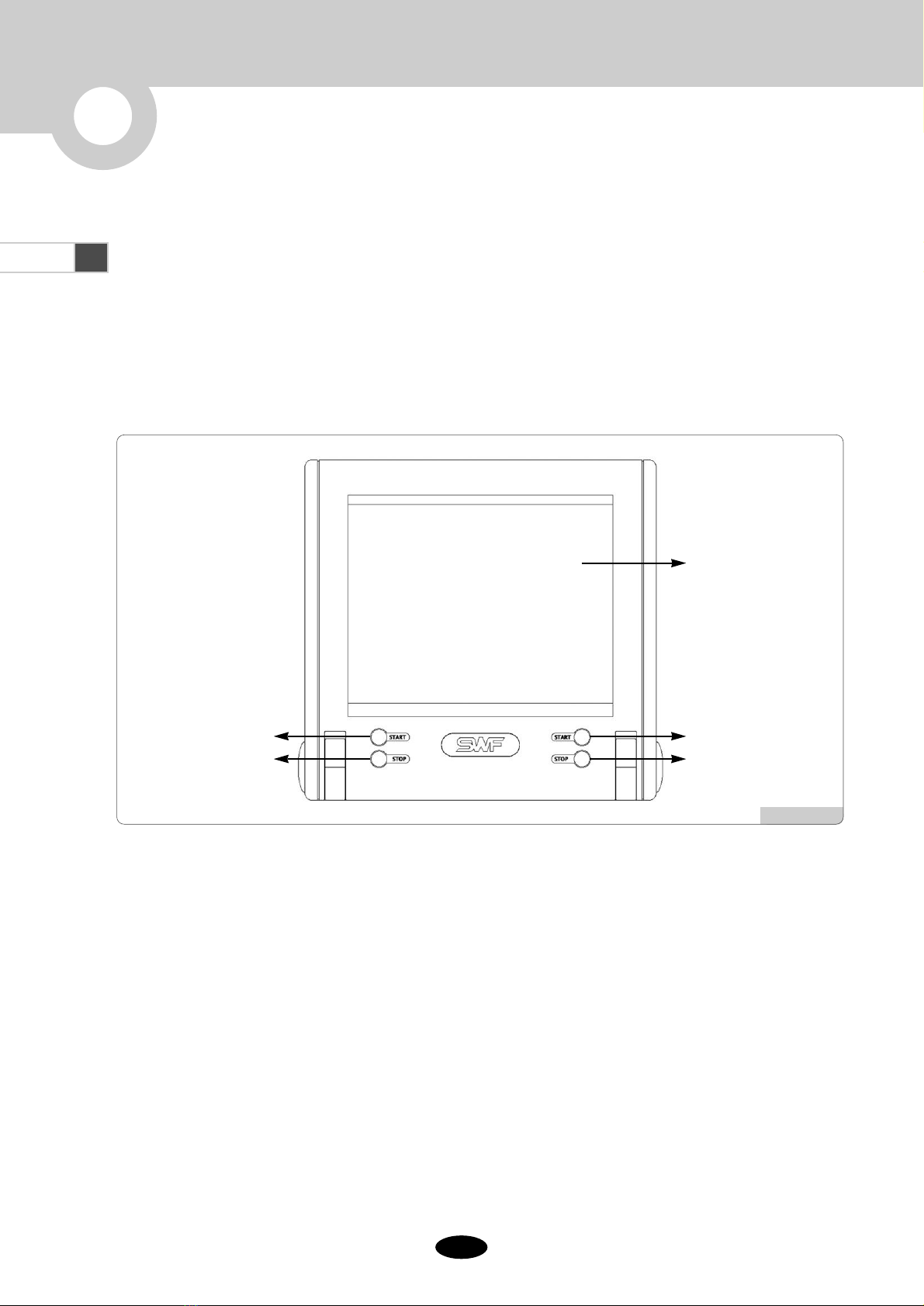
It is a touch screen-type color LCD monitor, which displays all information necessary for embroidery work.
When desiring to perform a function, the function key can be pressed using a touch screen pen or a finger.
Start
To start embroidery.
Stop
To stop embroidery.
1.1 Names and Functions
Dual Function Series Embroidery Machine is a high-performing embroidery machine, since it works as much as two
embroidery machines. It has a touch-screen type Operation Box as shown in [Fig. 1.1-1]. The OP Box can be folded and
fixed with the panel on the back. It is not required to attach the OP Box to the embroidery machine, so that it can be
placed wherever the user wants to put. The cable and ports are located on the right and rear side of the OP Box.
[Fig1.1-1]
1
DUAL Function Series Embroidery Machine Operation Box
▶
Front
StartStart
Stop Stop
LCD screen
[Fig1.1-2]
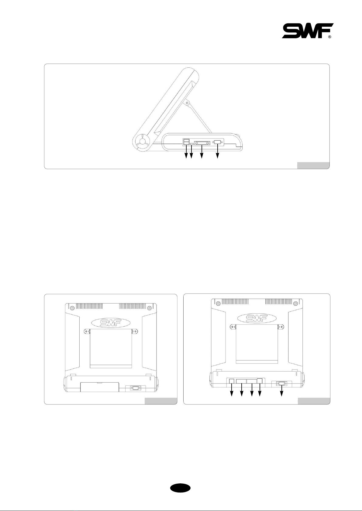
[Fig1.1-3] [Fig1.1-4]
USB Port (Master)
Designs can be uploaded to or downloaded from the USB memory through the ports.
USB Port (Slave)
Designs can be uploaded to or downloaded from the USB memory through the ports.
(This is under development.)
Connecting floppy drive to the cable
The portable floppy disk drive can be connected to the cable.
Serial Port
Serial port can be used for serial communication.
The connector cover is designed to prevent dusts and other foreign materials from gathering. When linking to
the connector, press the cover to open it.
Keyboard Port
VGA (Monitor) Port
Serial Port
LAN Port for networking
Cable connection for power signal transmission
▶
Right
▶Back
Refer to the following examples of the keys frequently used in the menu screen.
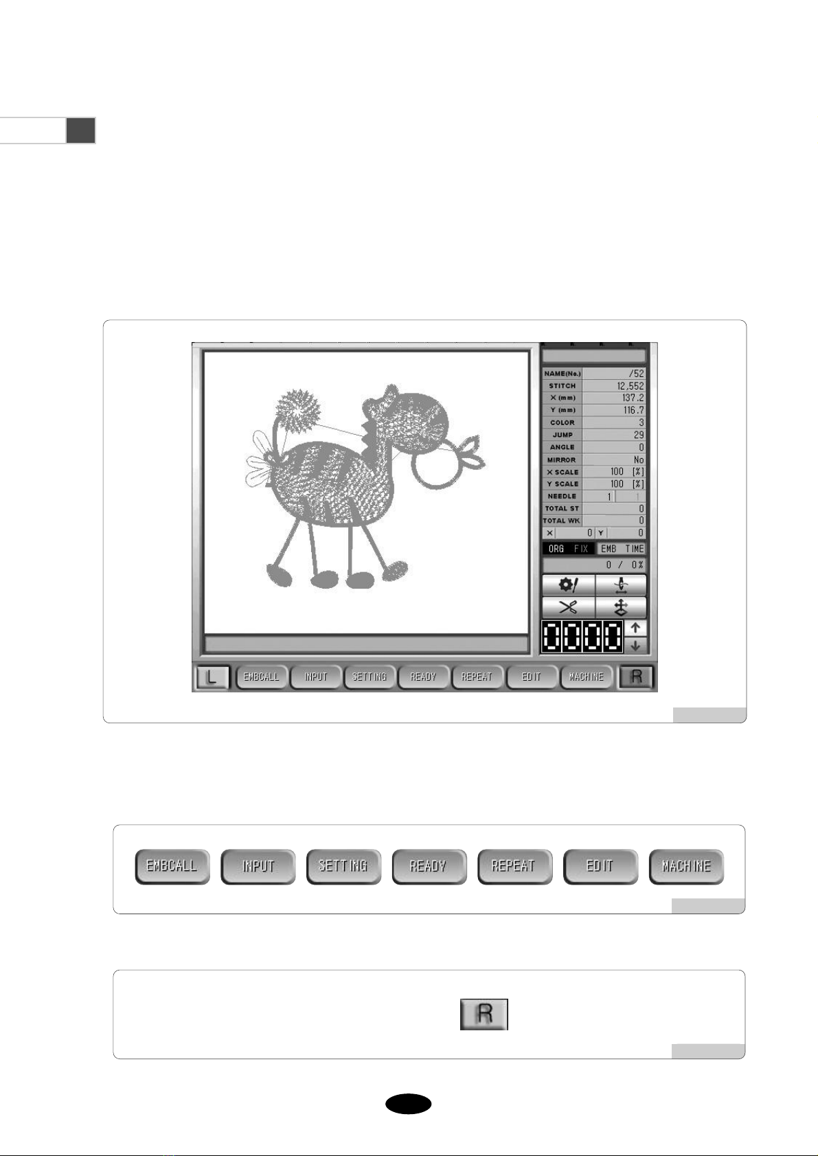
[Fig.1.2-2] shows a set of function menus. Each menu offers specific functions.
1.2 LCD monitor
The OP Box of Dual Embroidery Machine has a touch screen monitor.
The touch monitors are slightly different from the existing keypad-type monitors.
You are simply to touch the desired menus on the screen using touch pens or your fingers. Press the menu and you will
see one or more sub menus. [Fig.1.2-1] shows the display of the operating program of the Dual Embroidery Machine.
[Fig1.2-1]
[Fig1.2-2]
[Fig1.2-3]
[Fig. 1.2-3] shows the button used to change the embroidery operation program screen.
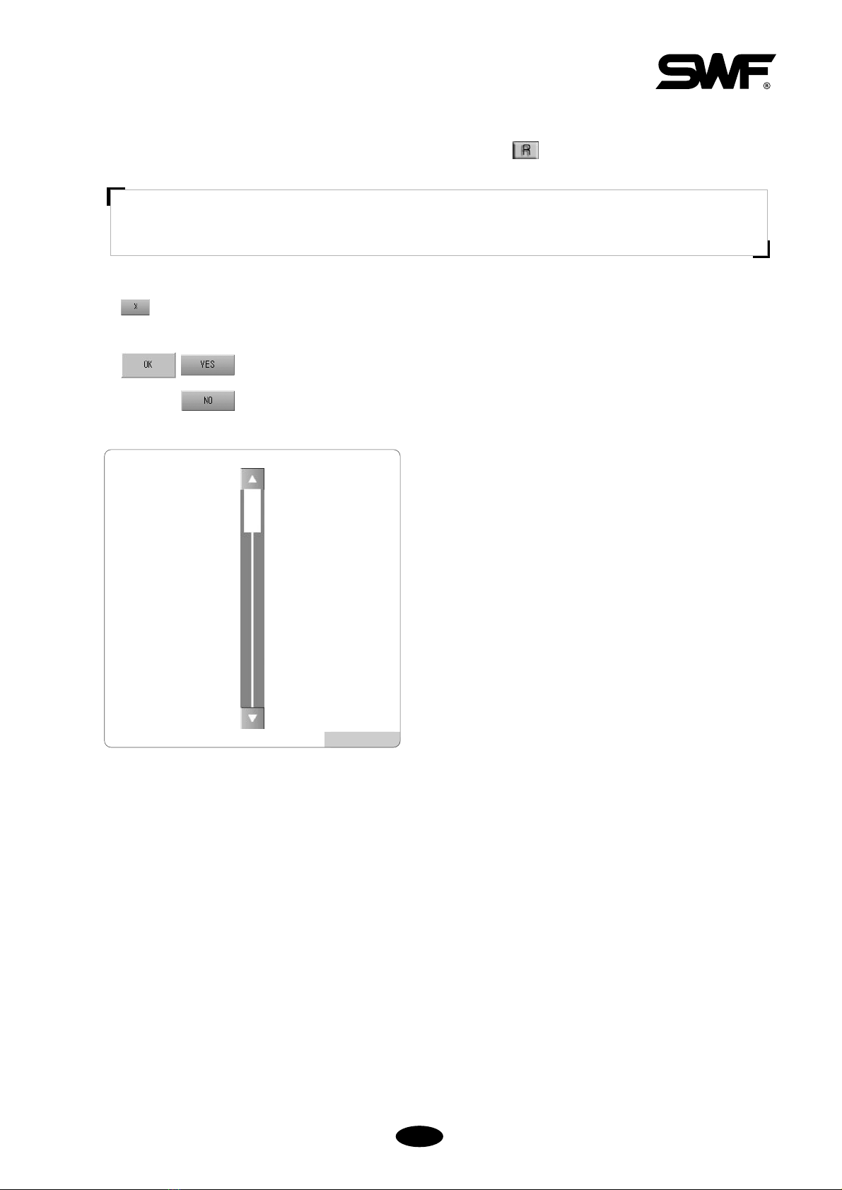
END : End the command execution.
It closes the work window where the command is executed.
Ok, Yes : Confirm whether the command is correct or execute it.
Cancel, No : Cancel the execution of a command.
[Fig1.2-4]
You can see in [Fig.1.2-4] a scroll bar and an Up/Down key. To
see the next screen, simply drag down the scroll bar or press
Up/Down key.
As in <Fig.1.2-1>, the button on the currently chosen screen is turned yellow, meaning that it is activated.
In order to choose the operating program screen of MC2, choose the gray button, which is currently deactivated.
If the message “System Initial” still remains even after the screen is changed, the power might not be turned
on or the machine might not be initialized. Close the message window and check the machine.
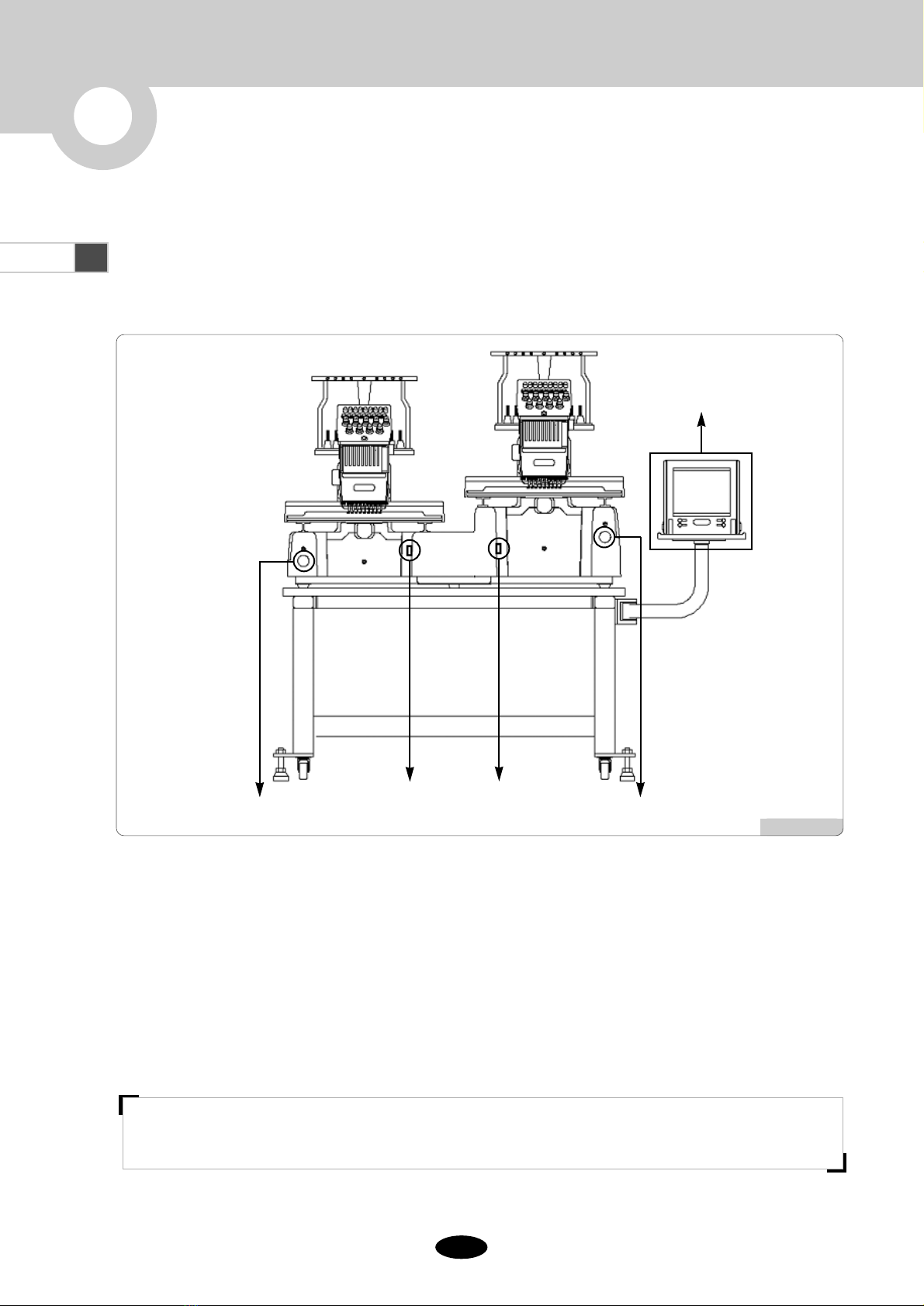
2.1 Power ON
2
Basic Procedures of Embroidery
[Fig.2.1-1]
OP Box
MC2 Emergency switchMC1 Emergency switch
MC2
Power switch
MC1
Power switch
Plug in the embroidery machine and turn on the power switch of MC1. Then the LCD screen of the OP
Box is turned on, and the embroidery machine operation program is displayed on the screen.
Plug in the embroidery machine and turn on the power switch of MC2. Then the LCD screen of the OP
Box is turned on, and the embroidery machine operation program is displayed on the screen.
(When either MC1 or MC2 is switched on, the OP Box will be turned on.)
Press the frame move button to check if the frame is moving properly. Or check the basic motions of
the frame following the instructions in “5.13.3 Operation Check.”
[WARNING]
Make sure to turn OFF the power when repairing the machine.
This manual suits for next models
3
Table of contents
Other SWF Sewing Machine manuals


