SWF E-U901 User manual

MANUAL
SSiinnggllee HHeeaadd BBrriiddggee
AAuuttoommaattiicc EEmmbbrrooiiddeerryy
MMaacchhiinnee
SSUUNNSSTTAARR PPRREECCIISSIIOONN CCOO..,, LLTTDD..
MMMMEE--006600442244

1. THIS IS AN INSTRUCTION FOR SAFE USE OF AUTOMATIC
EMBROIDERY MACHINES. READ THOROUGHLY BEFORE USE.
2. CONTENTS IN THIS INSTRUCTION MAY CHANGE, WITHOUT
PRIOR NOTICE, FOR IMPROVEMENT OF MACHINE QUALITY AND
THUS MAY NOT CORRESPOND TO THE MACHINE YOU
PURCHASED. CONTACT YOUR SALES AGENT FOR INQUIRIES.
3. THIS IS DESIGNED AND MANUFACTURED AS AN INDUSTRIAL
MACHINE. IT SHOULD NOT BE USED FOR OTHER THAN
INDUSTRIAL PURPOSE.

4
Contents
1. MACHINE TYPE AND SPECIFICATIONS ....................................................................................................................................... 6
1.1) MACHINE TYPE.......................................................................................................................................................... 6
1.2) MODEL TYPE .............................................................................................................................................................. 6
1.3) SPECIFICATIONS ....................................................................................................................................................... 6
1.4) ACCESSORIES ............................................................................................................................................................ 6
1.5) OPTIONS .......................................................................................................................................................................6
2. SAFETY RULES ................................................................................................................................................................................................... 7
2.1) SAFETY STICKERS ................................................................................................................................................... 7
2.2) MACHINE DELIVERY................................................................................................................................................ 8
2.3) MACHINE INSTALLATION ...................................................................................................................................... 9
2.4) MACHINE OPERATION ............................................................................................................................................ 9
2.5) REPAIR AND MAINTENANCE .............................................................................................................................. 10
3. DISTINCTIVE FEATURES.............................................................................................................................................................................. 11
4. MATTERS TO CONSIDER REGARDING MACHINE INSTALLATION ................................................................. 13
4.1) INSTALLATION CONDITIONS .............................................................................................................................. 13
4.2) ELECTRICITY ENVIRONMENT ............................................................................................................................ 14
4.3) BALANCE ADJUSTMENT ...................................................................................................................................... 14
5. SAFETY RULES FOR MACHINE OPERATION ...................................................................................................................... 16
5.1) TYPES OF SAFETY LABELS ................................................................................................................................. 16
5.2) LOCATION OF SAFETY LABELS .......................................................................................................................... 17
6. PARTS NAME ...................................................................................................................................................................................................... 18
7. ASSEMBLY OF ACCESSORIES ......................................................................................................................................................... 19
7.1) ASSEMBLY OF UPPER THREAD STAND ............................................................................................................ 19
7.2) ASSEMBLY OF OPERATION BOX ........................................................................................................................ 19
8. FUNCTIONS OF EACH PART AND OPERATION METHODS ................................................................................... 20
8.1) LAMP SWITCH ON THREAD TENSION ADJUSTING PLATE .......................................................................... 20
8.2) NEEDLE STOP CLUTCH ......................................................................................................................................... 21
8.3) UPPER THREAD PLACEMENT AND TENSION ADJUSTMENT ....................................................................... 22
8.4) LOWER THREAD PLACEMENT AND TENSION ADJUSTMENT ..................................................................... 26
8.5) THREAD WINDING ................................................................................................................................................. 27
8.6) ADJUSTMENT OF NEEDLE AND HOOK TIMING AND OTHER RELATED INFORMATION ...................... 29

5
Contents
8.7) ASSEMBLY OF THREAD SENSOR AND FUNCTIONS ...................................................................................... 34
9. MAINTENANCE AND CHECKPOINTS ........................................................................................................................................... 35
9.1) REGULAR CHECKUP .............................................................................................................................................. 35
9.2) CLEANING ................................................................................................................................................................ 35
9.3) OIL SUPPLY .............................................................................................................................................................. 37
9.4) GREASE SUPPLY ..................................................................................................................................................... 39
9.5) TENSION CHECK OF EACH DRIVING BELT ...................................................................................................... 41
10. ADJUSTMENT .................................................................................................................................................................................................. 42
10.1) ADJUSTMENT OF TRIMMER .............................................................................................................................. 42
10.2) ADJUSTMENT OF TRIMMER RETURN SPRING LOCATION ......................................................................... 44
10.3) ADJUSTMENT OF PICKER ................................................................................................................................... 44
10.4) ADJUSTMENT OF UPPER THREAD HOLDING DEVICE ................................................................................ 45
10.5) ADJUSTMENT OF UPPER THREAD HOLDER .................................................................................................. 46
10.6) ADJUSTMENT OF NOISE CONTROLLER FOR PRESSER FOOT .................................................................... 47
10.7) RELATIONS BETWEEN PRESSER FOOT AND NEEDLE ................................................................................ 48
10.8) ADJUSTMENT OF HALF TURN FILM FOR COLOR CHANGE ....................................................................... 49
10.9) ADJUSTMENT OF ENCODER POSITION ........................................................................................................... 50
10.10) ADJUSTMENT OF NEEDLE BAR UP/DOWN POSITION ............................................................................... 51
10.11) ADJUSTMENT OF JUMP MOTOR ..................................................................................................................... 52
10.12) ADJUSTMENT OF TENSION OF EACH DRIVING BELT ............................................................................... 53
11. CAUSES OF TROUBLE AND TROUBLESHOOTING .................................................................................................... 57

6
MACHINE TYPE AND SPECIFICATIONS
01
1.5) OPTIONS
SQ20, SQ20F, boring device, coding device, wide frame, semi-wide frame
1.1) MACHINE TYPE
1.2) MODEL TYPE
1.3) SPECIFICATIONS
SWF/E-U1201
Series No.of Head
No.of Needle
Machine Type
0.1~12.7(mm)
Max. 1200 rpm
BLDC Motor ×1 (Main Shaft Motor)
Pulse Motor ×2 (Frame Driving Motor)
1-Phase 100V, 110V, 120V, 200V, 220V, 240V(50~60Hz)
600W
Stitch Length
Speed
Motor
Power Source
Power Consumption
1.4) ACCESSORIES
Standard
Max. 2,000,000
USB Memory Stick, External Type FDD
Option : 1.7 Fold Capacity Hook
Fluorescent Lamp, Semi-Wide Cap Frame, Wide Cap Frame, Sequin Device, Boring Device
Standard
Bobbin Winder
Memory Capacity
Memory Medium
Hook
Device
Position Marker
Machine
E-U901
E-U1201
E-U1501
9
12
15
1
1
1
520×450 419×439 360×75 180×83
Color Head Tubula Tubular Wide
Cap Frame
Semi-Wide
Cap Frame
Boarder Frame
A
1270
B
1375
C
1519
D
725
E
1185
Emb. Space (mm) Machine Size (mm)

SAFETY RULES
02
7
2.1) SAFETY STICKERS
The safety stickers in this user's manual are divided into , , and . They indicate
that if the safety rules are not kept, injury or damage to machine might occur as a result.
WarningDangerCaution
No. Name Description
CAUTION
WARNING
DANGER
Caution If the machine is not properly handled, it may cause injury
to users or physical damage to the machine.
If the machine is not properly handled, it may cause death or
severe injury to users.
If the machine is not properly handled, it may cause death or
severe injury to users, and the urgency of the danger is very
high.
Warning
Danger

8
2.2) MMAACCHHIINNEE DDEELLIIVVEERRYY
DANGER
WARNING
The machine delivery shall be conducted by the persons who are knowledgeable
about the safety instructions and rules. The following safety rules must be observed:
2.2.1) Crane-based delivery
The crane in use shall be big enough to lift the machine, and a nylon rope with
sufficient intensity shall be used. When using the rope, insert a square wood brick
between the rope and the each side of the machine which is touched by the rope. The
hanging angle should be 40 degrees at the maximum. Make sure that the nylon rope
does not directly contact the table.
2.2.2) Forklift-based delivery
1) A forklift shall be big enough to endure the weight of the embroidery machine and
carry the machine.
2) When lifting the machine, align the fork arm of the forklift with the gravity center
of the machine as in the figure below, and lift the machine from behind. Then,
make sure to prevent the machine from leaning toward one side.
Make sure to maintain the balance of the machine when unloading the
machine by using a forklift or crane to prevent the deformation of the
machine or to prevent people from being exposed to danger.
WARNING
※Ban people
from standing
under the
machine and
remove
obstacles near
the machine.
※If possible, use a
crane to deliver
the machine.
Only when it is
impossible to
use a crane, use
a forklift (Make
sure that a crane
and a forklift in
use are durable
enough to ensure
the weight of the
machine).
Sticker Description
Nylon Rope
Square wood brick

9
2.3) MACHINE INSTALLATION
DANGER
Depending on the installation environment, function errors, breakdown, or other
physical damage might result. Make sure to meet the following conditions for machine
installation:
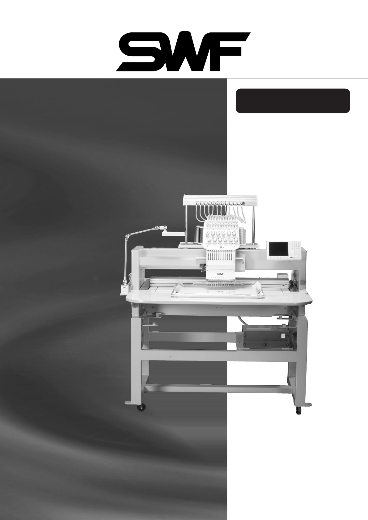
1) The place where the machine is installed shall have the structure to endure the weight
of the machine (some 500 kg).
2) Dust and humidity are the cause of machine pollution and erosion. Please install an air
conditioner and conduct regular maintenance of the machine.
3) Install the machine at the place where it is not exposed to direct sunlight (if the machine
is exposed to direct sunlight for a long time, it may cause discoloration or deformation).
4) Secure the space around the machine. Place the machine at least 50cm away from the
left, right, and rear walls to secure sufficient space for maintenance activities.
[Note] For more details on machine installation, see "2. Machine Installation and
Assembly."
2.4) MACHINE OPERATION
The SWF automatic embroidery machine is designed to conduct embroidery on
textiles and similar materials for industrial purposes.
The machine body is attached with " " and " " stickers at
dangerous parts to emphasize safety instructions. With the full understanding of the
safety instructions, make sure to observe the following during machine operation:
1) Before using the machine, read this manual thoroughly and have a full understanding of
machine operation.
2) Get properly dressed. Long hair, necklace, bracelet, or wide sleeves might be fed into
the machine during operation. Wear slip-free shoes to prevent slipping on the floor.
3) Make sure that no one is working within the operating scope of the machine before
starting the machine.
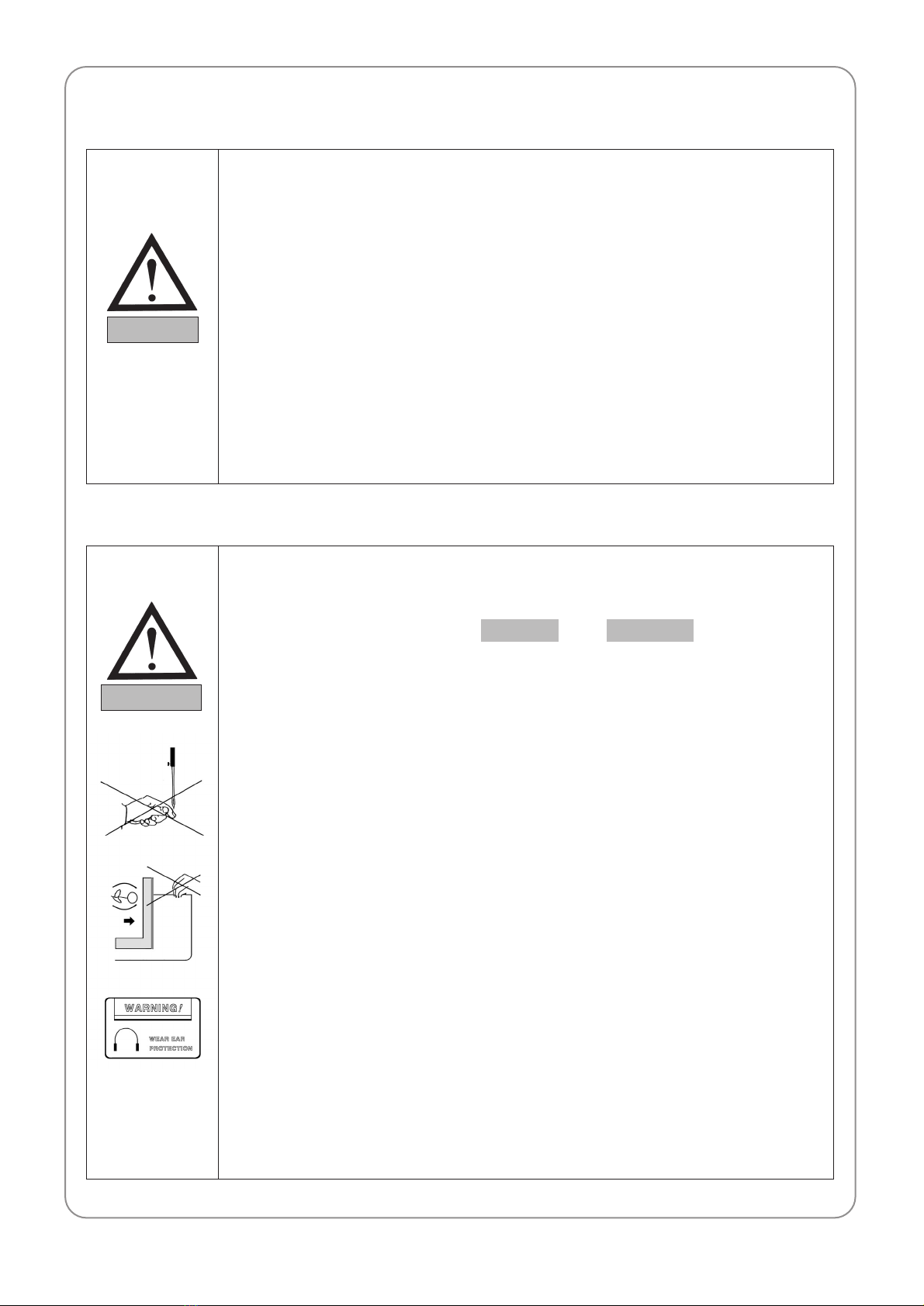
4) Keep hands and head away from the machine parts where accidents might occur
(needle, hook, thread take-up, pulley, etc.) during operation.
5) Do not remove the safety cover which protects pulley and shaft during machine
operation for user's safety.
6) Cut the power supply before disassembling the electric box such as the control box, and
double-check that the power switch is "Off."
7) Make sure that the power switch is "Off" when the upper shaft is manually rotated.
8) Stop the machine when threading the needle or examining embroidery work after
embroidery is done.
9) Do not lean against the workbench and keep your hands away from the guide home of
the panto-graph. You may hurt your finger while the machine is in operation.
10) When the machine operates at the full speed, the noise level might go over 85db.
However, since this is only the standard value, to protect users and prevent disturbance
of other work by the noises, it is better to use ear plugs or install the soundproof device.
WARNINGCAUTION
WARNING

10
2.5) REPAIR AND MAINTENANCE
DANGER
When machine repair is needed, it shall be conducted by SunStar A/S engineers only
who have finished the due training course.
1) For cleaning and repair, cut the main power supply. Wait for 4 minutes before starting
maintenance to make the machine completely discharged.
2) Do not modify the machine specifications or parts without substantial consultations
with SunStar. Otherwise, it may threaten safety during machine operation.
3) Use the parts manufactured by SunStar to repair or replace the machine parts during
A/S service.
4) When repairing is completed, re-install all the removed safety covers.
For main shaft motor and X,Y drive box, it takes 10 minutes
before they are completely discharged after the main power is
cut.
CAUTION

DISTINCTIVE FEATURES
03
11
(1) Expanded Memory Capacity
Up to 100 design patterns can be stored, and the maximum memory capacity per design pattern is 2 million
stitches.
(2) Mirror Change and Design Direction Setting
A design can be rotated at the range from 0° to 359° by the unit of 1°, and the mirror change (X-direction
reversing) can be conducted.
(3) Zoom-in/Zoom-out
Within the range from 50% to 200%, an embroidery design can be magnified or reduced in the X or Y
direction by the unit of 1%.
(4) Automatic Selection of Needle Bar
The needle bar order can be chosen and set up to 99.
(5) Regular Repetitive Work
A same design can be set to be embroidered in the X or Y direction up to 99 times.
(6) Special Repetitive Work
The embroidery of various designs can be conducted with the variation of mirrors and angles as desired, and
up to 63 designs can be set.
(7) Automatic Offset
To ensure easy replacement of an embroidery frame, the frame can be set to automatically return to the offset
point when embroidery work is completed. Go to the parameter setting mode and turn on the automatic offset
function. Then, the frame will automatically move to the pre-set position, making the application work and the
frame replacement easy.
(8) Manual Offset
In the middle of embroidery work, to make the application work and the frame replacement easy, the frame
can be set to manually return to the pre-set position. After the manual offset is conducted, with a simple key
pressing, the frame can go back to the original position before the manual offset is conducted
(9) Return to Origin
In the middle of embroidery work, the frame can be returned to the design starting position.
(10) Operating Without Stitching
Without stitching, it is possible to move forward or backward the frame by the desired number of stitches such
as 1 stitch, 100 stitches, 1000 stitches, and 10,000 stitches and based on the color code.
(11) Backward Motion of Frame
When the thread escapes or breaks, the frame can move backward to the design starting position by the unit of
1 to 10 stitches.
(12) Automatic Trimmer
Automatic trimmer can be automatically operated depending on design code and settings. Therefore, the

12
quality of finished work and productivity can be enhanced.
(13) Automatic Tread Break Sensor
When the upper thread breaks or the lower thread runs out, the sensor can detect it and automatically suspend
the machine operation.
(14) Upper Thread Holder
During sample embroidery, the device prevents the thread from escaping from unused heads and prevents the
upper thread from escaping during embroidery work replacement.
(15) Automatic Return to Forced Stop Position At Power Outage
When there is power supply problem, the frame can be automatically and accurately moved to the position
where it was stopped at the timing of power outage. This function reduces the bad rate of finished products.
(16) 3.5-Inch Floppy Drive Embedded
The 3.5-inch floppy drive is embedded into the operation panel as default so that designs can be input into the
machine by using a floppy diskette (2DD, 2HD also possible to use).
(17) Edit Function
Stitch data and functional codes (jump, close, trimming) can be deleted, changed, or inserted.
(18) Individual Head Operation
With other normal heads remaining untouched, it is possible to operate the heads with broken thread
individually.
(19) Display of the Cause of Machine Stop
(20) Display of RPM
(21) Frame Feeding Speed Setting
The feeding speed can be chosen among high, medium, and low.
(22) Display of Unused Memory
(23) 6.4-inch LCD Monitor Equipped
The 10.4-inch color LCD monitor is attached to the operation panel, showing all information related to
embroidery work at one sight.
(24) Automatic Recognition of Other Companies' Codes
Designs with various formats stored in a floppy diskette can be automatically recognized.
(25) Position Marker
When tracing a design, use the laser beam to check the locations of the frame and the hoop.
[Recognized Formats]
1. SST
2. DST, DSB, DS
3. TAP
4. FMC, FDR
5. ZSK
6. 100
7. EXP

MATTERS TO CONSIDER REGARDING MACHINE INSTALLATION
04
13
To ensure smooth operation of the project, prepare the installation environment in
compliance with the manual. Otherwise, it might cause unexpected break-down of the
machine.
CAUTION
4.1) IINNSSTTAALLLLAATTIIOONN CCOONNDDIITTIIOONNSS
4.1.1) Temperature
1) While the machine is in use: 0。~40。C (32。~104。F)
2) While the machine is in storage: -25。~55。C (-13。~131。F)
4.1.2) Humidity
1) Relative humidity: 45 ~ 85%
4.1.3) Grounding
Before installing the machine, the ground wire must be installed.
4.1.4) Ambient Environment
Keep windows and doors closed to prevent direct sunlight, dusts, and moisture from entering the work site.
4.1.5) Installation Place
The place where the machine is installed should be a concrete structure, which is strong enough to endure
the weight of the machine, and it shall be flat.
4.1.6) Category of Industrial Environment
The embroidery machine shall be installed and used within the industrial area.
(Industrial environment category: Class A)
1) Make sure that water drops are not formed on the surface of the machine.
2) Please install the air condition in order to adjust humidity and prevent dust gathering
and machine erosion.
CAUTION
There exists the danger of getting electric shock due to electric leakage. To prevent this,
install the earth wire of the machine on the ground. The level of grounding shall be over
grade 3 (grounding resistance <=100Ω)
DANGER

14
4.2) ELECTRICITY ENVIRONMENT
4.2.1) Input Voltage (need to be adjusted upon installation)
1 phase AC 100V ~ AC 240V
4.2.2) Allowable Voltage Range
Rated voltage ± 10%
4.2.3) Power Capacity and Power Consumption
600W
4.2.4) Insulation Resistance
10M Ωor above (measured by the 500V insulation tester)
4.3) BALANCE ADJUSTMENT
1) Assemble the adjusting bolts for leveling (4EA) on the machine stand as in the figure below. Place the
vibration-free rubber (4EA) under the adjusting bolts for leveling. Fasten the adjusting bolts for leveling until
the casters emerge above the ground. Use the level gauge to balance the machine on the four directions
including front, back, left and right. When the level adjustment is completed, tightly fasten the fixing nuts.
Make sure to check whether the power specifications of the machine match with those of
the power supply before installing and operating the embroidery machine.
WARNING
1) Check the power voltage of the place where the machine is installed.
2) The users might fall over the power cables of the machine. Therefore, when installing
them, keep them away from the working area.
WARNING
If the machine is not balanced (in particular the machine's front and back), the machine
might get deformed or the needle positions will get inappropriate. Therefore, it is necessary
to adjust the balance of the machine.
CAUTION

15
2) When adjusting the level of the machine, the four directions including front, back, left and right shall be
adjusted.
3) Position of Level Gauge
Level Gauge
1) Check the power voltage of the place where the machine is installed.
2) The users might fall over the power cables of the machine. Therefore, when installing
them, keep them away from the working area.
3) If the height difference between 4 adjusting bolts is 10mm or above, put some plates
under the low level bases in order to reduce the gap.
CAUTION

SAFETY RULES FOR MACHINE OPERATION
05
16
5.1) TYPES OF SAFETY LABELS
※※Watch Out for Needle!
When threading needles or replacing the needles, make sure to stop the
machine. Otherwise, you may get your hands hurt.
※※Watch Out for High-Voltage Electricity!
You may get an electric shock. Except for A/S service engineers, do not
open the cover. To open the cover, turn off the power and wait for 6
minutes before opening the cover.
※※Watch Out for the Opening!
Do not insert your hands stuck between the tables.
※※Do not place your hand!
If your hand is placed between the frame and the machine structure,
depending on the moving direction of the frame, you may get your
hands hurt.
※※Watch Out for Spinning!!
Make sure to close the cover before operating the machine. While the
machine is in operation, do not keep your hands close to the machine
parts, which are in motion. Otherwise, you may get your hands hurt.
※※Watch Out for Spinning!
While the machine is in operation, keep your hands away from the
needle bar and the thread take-up.
Fully understand the contents of the safety labels attached to the machine to prevent any
safety accidents from occurring.
CAUTION
Injury may be caused by moving
needle.
Ensure that the machine is in a
stop condition before changing,
threading or rethreading of
needies or changing of needles.
WARNING
WARNING
Fire or death may be caused by
high voltage electric shock.
Don’t open the cover except for
service man assigned by SWF.
When open the cover turn off
power and wait for 6 minutes.
WARNING
Physical injury may be caused
by crevice.
Don’t put your finger in a groove
on the table.
Physical damage may be caused
by interposition.
While embroidery frame is running
according to the direction of
embroidery frame may be injured
your hands by gap between fixed
body and embroidery frame.
WARNING
Injury may be caused by winding.
Be sure to turn off the power
before cleaning, lubricating,
adjusting or repairing.
WARNING
Physical damage may be caused by
winding.
Don’t put your hands near the
needle bar & take-up lever while
machine is running.
WARNING

17
5.2) LOCATION OF SAFETY LABELS
To ensure safe operation of the machine, various warning stickers are attached to the machine. Strictly follow
the directions on the safety labels during the operation of the machine.
Injury may be caused by winding.
Be sure to turn off the power
before cleaning, lubricating,
adjusting or repairing.
WARNING
WARNING
Physical injury may be caused
by crevice.
Don’t put your finger in a groove
on the table.
Physical damage may be caused
by interposition.
While embroidery frame is running
according to the direction of
embroidery frame may be injured
your hands by gap between fixed
body and embroidery frame.
WARNING
WARNING
Fire or death may be caused by
high voltage electric shock.
Don’t open the cover except for
service man assigned by SWF.
When open the cover turn off
power and wait for 6 minutes.
Injury may be caused by moving
needle.
Ensure that the machine is in a
stop condition before changing,
threading or rethreading of
needies or changing of needles.
WARNING

PARTS NAME
06
18
①Machine body
②Table
③Upper Thread Stand
④Main Shaft Driving Motor
⑤Rotary Hook Base
⑥Trimmer Driving Box
⑦Regular Arm
⑧Color Change Box
⑨Upper Thread Holder
⑩Head
⑪Thread Tension Adjusting
Plate
⑫Main Controller Box
⑬X-shaft Feed System
⑭Y-shaft Feed System
⑮Thread Guide
⒃Lamp
⒔Operation Box
⒕Upper Thread Holder Motor
⒖Encoder
⒗Upper Thread Holding
Main Power Switch
Level Base
Thread Break Sensor
Laser Pointer

ASSEMBLY OF ACCESSORIES
07
19
7.1) ASSEMBLY OF UPPER THREAD STAND
7.2) AASSSSEEMMBBLLYY OOFF OOPPEERRAATTIIOONN BBOOXX
Thread Hanging Angle
Supporter
Spool Plate
Power Cable
FDD Cable

FUNCTIONS OF EACH PART AND OPERATION METHODS
08
20
8.1) LAMP SWITCH ON THREAD TENSION ADJUSTING PLATE
8.1.1) Function of Switch
1) During normal operation, locate the toggle switch on "Lamp On" to keep the lamp on.
2) When the machine stops its operation after the thread break is sensed, move the frame backward until the
position where thread is broken. When operating the machine again, the heads with broken thread will start
embroidering from the place. In this way, the embroidery design can be corrected.
3) In order to fix a needle bar so a specific head cannot carry out embroidering, turn off the lamp by placing the
toggle switch on "Lamp Off."
8.1.2) Thread Break Detection
When upper thread break or lower thread break is detected, the concerned lamp blinks and the rest lamps are
turned off. For the lamps which are automatically turned off at this time, they cannot be turned on or off again
by using the toggle switches.
Thread Sending Roller
Toggle Switch
Lamp
Thread Break Sensing Switch
On
ON Off
Off
To start embroidering from the reversed position by using the frame reverse function
(regardless of the detection of broken thread), first turn off the toggle switch and turn it on
again.
REFERENCE
For the heads and needle bars, which are not in operation for the current embroidery work
by turning their toggle switches off, the upper thread holder fixes their threads to prevent
their threads from escaping the needles.
REFERENCE

21
Manual Jump Clutch Lever
8.1.3) Disabling of Thread Break Sensor
If the thread sensing rollers do not properly rotate due to foreign materials stuck around the thread sensing rollers,
the machine could continue to detect thread breaks, interrupting the continuity of embroidery work. Then, as in
the figure below, move the toggle switch located on the back of the tread tension adjusting plate toward "thread
break sensor off." Then the thread break sensor function for the concerned head is turned off, and the embroidery
work can be continuously conducted.
8.2) NEEDLE STOP CLUTCH
As in the figure below, if the manual jump clutch lever is pulled forward from behind, the needle bar operation
will be suspended, and it becomes possible to conduct the jump work.
If the thread sensing rollers do not properly rotate due to foreign materials stuck around
the thread sensing rollers, the machine might regard it as thread break.
CAUTION
1) Although the needle bar operation is suspended due to the operation of the manual
jump clutch, the trimmer and the tread take-up lever of the concerned head are still
moving. Therefore do not conduct any operations for the concerned head, such as
threading and thread exchange.
2) If the mechanical clutch is used for a long time, the controller of the needle bar of the
head might be physically damaged.
CAUTION
This manual suits for next models
2
Table of contents
Other SWF Sewing Machine manuals