SWF SB Flat User manual

SB Flat Installation Manual
Contents
1. Check installation tools
2. Check Installation environment
3. Check and adjust levelness
4. Assembly
(1) Checking Machine Exterior
(2) Assemble Spool Stand
5. Runing Test
6. Check and adjust needle drop position
7. Check needle bar upper dead/needle drop point
8. Check and adjust rotary hook timing.
9. Machine motion test and running test.
10. Embroidery test
SUNSTAR Co.Ltd Page 1 Of 11 SWF CS Center

1Check installation tools
(1) Needle bar setting JIG (17.7MM)
(2) Needle drop point gauge. (+,- gauge)
Used for adjusting front and rear the needle drop point (+ Gauge: 0.1T 0.2T, - Gauge : 4.3T,4.0T)
(4) Tester (needed for checking voltage)
(5) Embroidery machine A/S tool box - one set
2Installation environment check before actual installation
(1) Environment
1) Temperature
When M/C is in operation:0。~40。C (32。~104。F)
When M/C is not in operation:-25。~55。C (-13。~131。F)
2) Humidity
Relative:45~90%
3) Environment Condition
Close any doors and windows near the machine to prevent direct light, dust, and humidity.
4) Ground Condtion
Foundation under the machine must be a sufficiently strong and flat concrete to support the weight
of the machine.
(2) ELECTRICITY CONDITION
1) Input voltage : Allowed range, within ±10% of the voltage set
2) Check Volatage Specification for M/C (Tag & Sticker on Control Box) and then Input Voltage.
※ M/C Input Voltage can be checked with Main Power S/W and refer to below.
- Disasemble Cover on Picture 1 with MAIN S/W OFF and check Voltage with tester on Picture 2.
- Adjust Input Voltage if it is different from M/C Specification.
- It shoud be around 120V in case of ground if machine is 220V in picture 3.
Picture 2
Picture 1 Picture 3
SUNSTAR Co.Ltd Page 2 Of 11 SWF CS Center
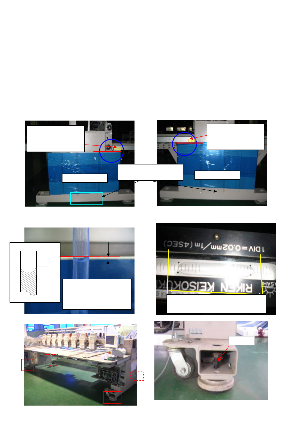
3Check and adjust levelness
(1) Check machine exteriors and level the machine.
※ Care if the air is in hose, bent when leveling with water hose.
1) Left/Right Levelness : Within 5mm with water hose
2) Front/Rear Levelness : Use Leveling Tool within 2/100 tolerance without any dust.
(Within 3 scale in left & right from center, Within 6/100 tolerance in left & right)
3) Check left/right and front/rear levelness
※ Do not use leveling tool like table which is not a standard position.
※ Check the water horizontality carefully and if it is changed, level it again.
Bolt
At the point marked by O, level
the height of water and body
to be within 0.5mm error
range. Level front/rear within the range.
X
O
Side (Left) Side (Right)
Check front&rear with
Leveling Tool and left &
right with water hose.
Check front&rear with
Leveling Tool and left &
right with water hose.
Control Beam Height by
Height Equipment.
SUNSTAR Co.Ltd Page 3 Of 11 SWF CS Center

※ Make a gap within 10mm between M/C Stand and Level Base Botton, and if there is much gap,
use Iron or Rubber plate and adjust it.
4 Assembly
(1) Check machine exteriors
(2) Assemble spool stand
① Insert the spool stand to the spool stand stud bolt.
(Insert spool stand "A" to the thread tension plate)
② Fix thread holder angle "D" to the angle base. (Use M4L10 bolt to fix)
※ When using hose, attach hose "poiont A"
with tape. At that time, make a water in hose
with beam stanard line. then check water in
hose in B and level M/C. If B is lower than A,
be low M/C. If B is higher than A, be high M/C.
"A" "B"
Spool Stand Stud Bolt Spool Stand Fix Bolt
Spool Stand Stud Bolt
Picture 6
Spool Stand
Thread Holder Angle "D"
Fix Bolt
(M4 L10) 3mm T Wrench
Thread Holder Angle "D"
Angle Base
Picture 8 Picture 9
Thread Holder Angle Frame
SUNSTAR Co.Ltd Page 4 Of 11 SWF CS Center
③ Assemble the thread holder angle with spool stand.
(Insert spool stand to the groove of thread holder angle frame)
④ Fix the thread holder angle frame to the spool stand with fixing bolts. (Use 4mm T wrench)
⑤ Fix the spool stand to the spool stand stud bolt. (Use 2.5mm L wrench)
※If the fixing bolts are not properly locked to the spool stand and the angle, the spool stand
and the angle may shake or vibrate and make the actual machine vibration seem stronger.
5 Runing Test
3) Test runing 600rpm with design.
4) Check if lower shaft bearin
g
bushin
g
has de
p
arted, drive is overheated, and noise from fra
m
5) Check the vibration of machine.
6) Check the machine conditions after finishing the running test.
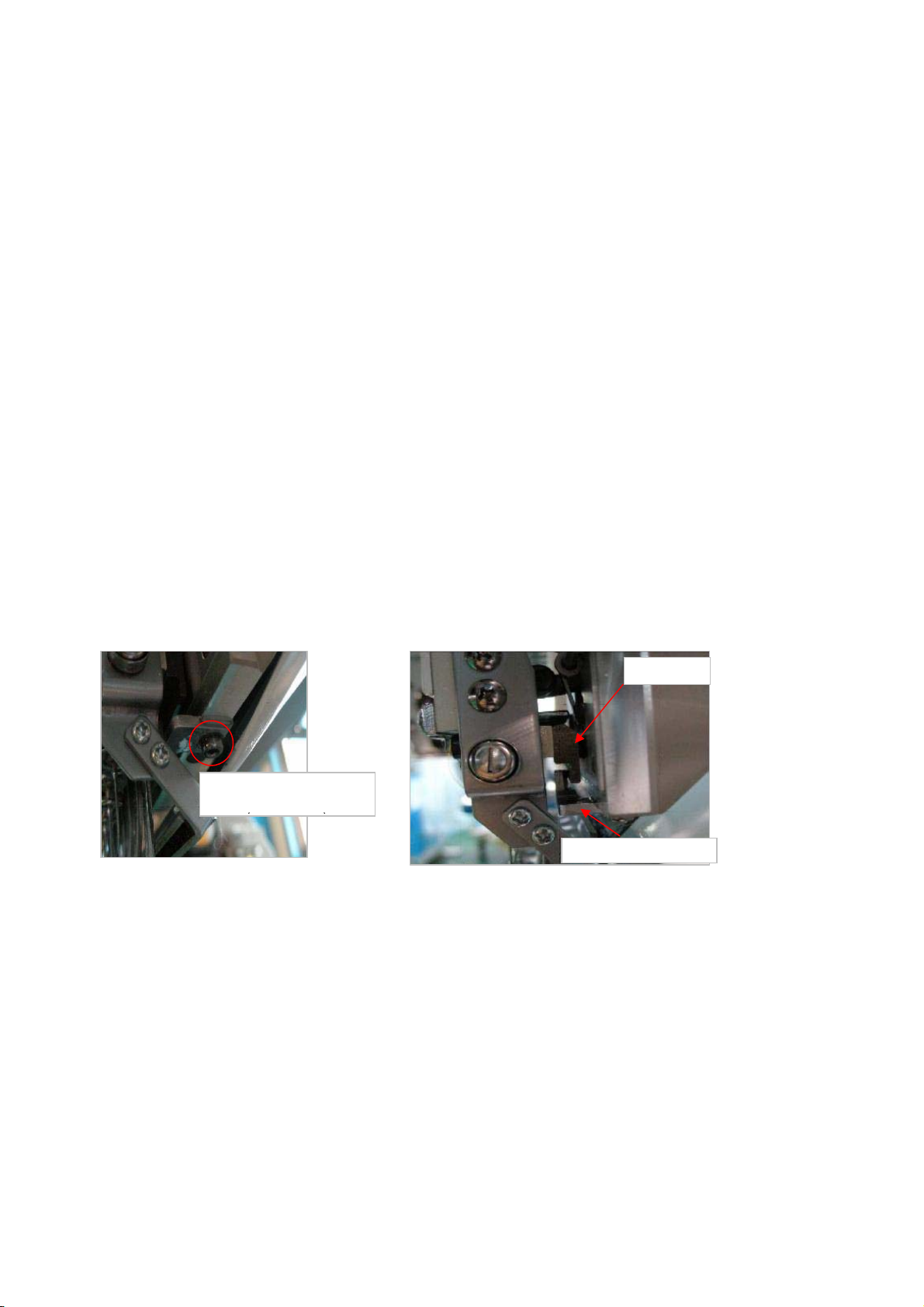
6 Check and adjust needle drop position
(1) Check the looseness of head.
1) Check the gap in between front and rear from the head at middle needle bar.
2) Change needle bar to the needle bar no.1 and check gap.
3 If there is a gap to front and rear of the head, use M3 L wrench to set the gap
to be within 0.1mm range (minimum). (Picture 10, 11 )
※ If the head gap/looseness is big/serious, thread cut and needle damage may occur.
If there is no gap/looseness, the part undergoes heavy load during C/C. Must be set
with the minimum gap/looseness.
(2) Check needle drop position.
1) Change C/C to Middle Needle Bar and Check Needle Position aroudn in 130~140˚.
--> Check Needle Spec. (DBK5#11) and Set it.
2) If it is not proper, reset it in middle needle bar and then check first and last needle bar.
(1) In case that needle drop position is in left and right
1) Check Needle Bar Position, Rotary Hook in first, middel, last needle bar.
(If Needle Bar Position, Rotary Hook is wrong, set it and then test runing.)
2) Cehck lubrication conditon in manual suply with 24cc in 10 times for ARM & BED.
Head Rail Holde Fix
Bolt
()
Picture 10
Head Rail
Head Rail Holder
Picture 11
SUNSTAR Co.Ltd Page 5 Of 11 SWF CS Center
- Adjust needle drop position after loosening bracket of head moving shaft by 4mm Wrench.
(2) In case of Front and Rear, loosen Head Rail bolt after disassembling Upper Thread Holder Base
(3) In case that needle drop position is in front
- Check whether Head Rail Gauge is between Head and Head Rail and If there is gauge, remove it.
- If Needle Drop position is in front after removing Head Rail Gauge, replace Head Rail
to another one. ※ Head Rail Spec. manufactured for E&K Tubular -> 4.4 T
(4) In case that needle drop position is in rear
- Insert Head Rail Gauge between Head and Head Rail.
※ Types of Head Rail Gauge → 0.1T, 0.2T, 0.3T
In case that needle
drop position is in
left and right.
Loose Upper Thread Hoder
Base Screw
Disassemble Head Rail
Screws
Head Rail
Head Rail Gauge
In case that needle
is in front
In case that needle
is in rear
SUNSTAR Co.Ltd Page 6 Of 11 SWF CS Center

7 Reset the needle bar upper dead/needle drop point.
(1) Check needle drop point.
1) Disassemble Needle Plate and rotage main shaft to 201 degree.
2) Insert needle drop point gauge between bed and needle bar and check gap.
If there is gap, reset needle upper/drop point.
3) Needle Drop Point Setting
Unlock the needle bar holder bolts, push down the needle bar to have it completely adjacent
to the jig.
Use T-wrench to lightly push up the needle bar holder and lock the needle bar holder bolt.
Try shaking JIG up/down to check the looseness/gap.
4) Needle Upper Dead Point Setting
1) Fix the angle of main shaft at 0. Push down the needle bar, push up the upper dead point stopper,
a
lock the bolt. Lightly hold upper dead point stopper and shake up/down to check for looseness/gap.
Looseness/gap may cause needle bar to not move properly.
Do not push up too much and do not allow looseness/gap when setting. (This may cause noise when
Disassemble Needle Angle 201
Insert Gauge (17.7mm)
Insert Gauge (17.7mm) (Side)
Pushing up Needle Bar holer slightly and fix holder screws.
SUNSTAR Co.Ltd Page 7 Of 11 SWF CS Center

running the machine.)
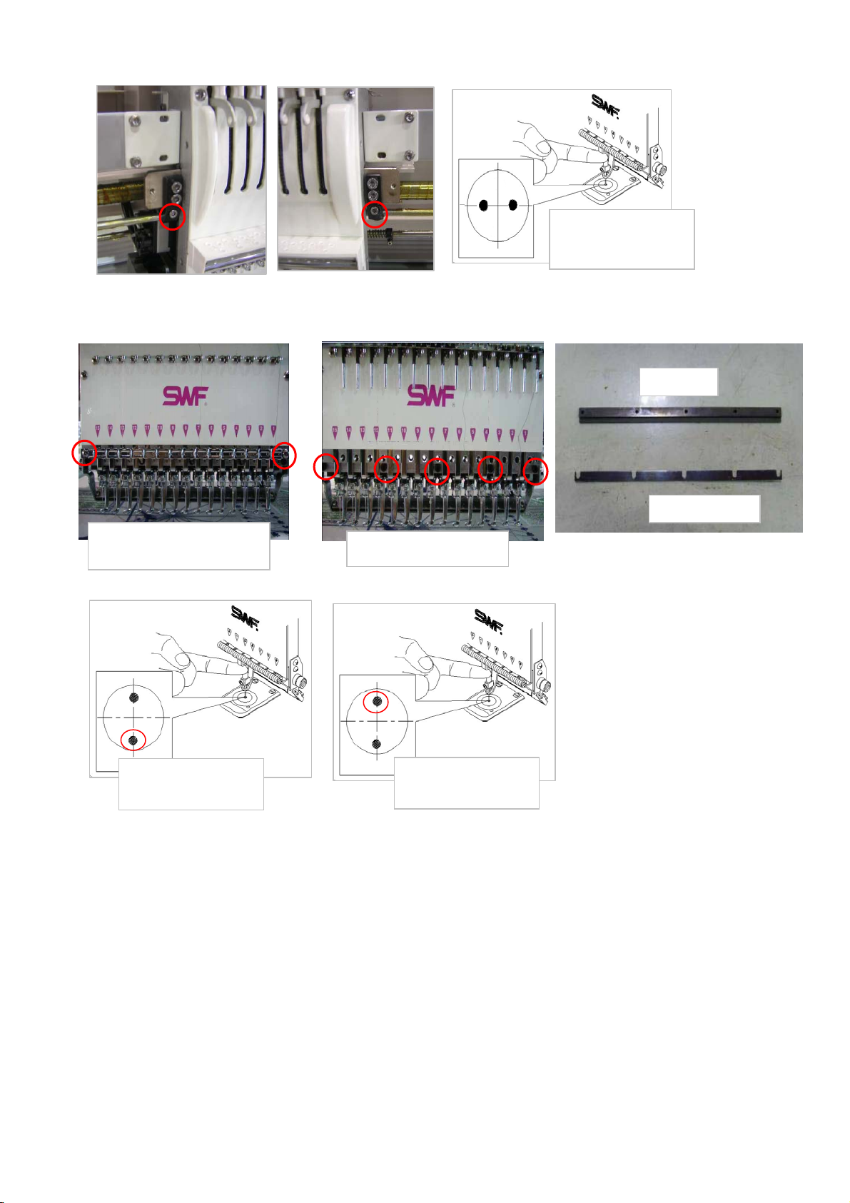
8 Check and adjust rotary timing.
Check if the needle is bent first before setting the rotary hook. Set the needle to right direction.
(Requirement for optimal loop formation)
(1) Check and adjust rotary hook timing and rotary hook gap. (Use "-" driver)
1) Fix the angle of main shaft at 201degrees. Check the position of the point of rotary hook
and looseness.
- If the point of rotary hook is not in a correct position or the rotary hook distance from needle
is big or none, reset.
- Place the point of rotary hook to the back of needle, and space it with 0.1~0.3mm intervals.
2) Rotary Hook Timing Setting
- Of the three fixing screws of rotary hook (point at 135 degrees and at 75 degrees),
unlock two screws from the center needle bar.
- Fix the angle of main shaft at 201degrees. Check the position of the point of rotary hook
and looseness.
- After setting the rotary hook, check the rotary hook looseness from First and Last Needle.
Lock all rotary hook Screws.
Upper Dead Point Stopper
Rotary Hook Support
Needle
Point of Rotary Hook
Set Gap (0.1~0.3mm)
Projection Part in Rotary Hook Support should be in
the center of Needle.
- Set Gap (0.5~0.7mm) from Hook.
SUNSTAR Co.Ltd Page 8 Of 11 SWF CS Center

2) Check and adjust rotary hook support position.
Adjust to have the part sticking out from the rotary hook support be in the center of needle. Unlock the fixin
g
screw of rotary hook support to adjust the gap between rotary hook and the support to within 0.5mm~0.7m
9 Machine motion test
(1) Machine motion test.
1) Design input test (USB/ FDD).
FUse FDD and USB to test the design input/output.
(User USB format confirm FAT format (allowed), FAT32 format (should not)).
2) Jump Motor motion test.
Check Motor condition all heads.
3) Wiper motion test.
Check the motion of each individual wiper. Check the conveyed quantity of wiper blades.
If wrong, adjust the pressure base setting.
4) Picker motion test.
Check the solenoid with motion test for each individual picker. Check the insertion amount
and the position of picker.
5) Upper thread holding motion test.
Check the upper thread holding device motion and how much holding device is opened.
6) Thread cutting motor motion test
Check the motion of thread cutting motor and distance moved and return position of movable mes.
7) Thread sensing motion test.
Check if there is anything wrong with the thread sensing board and status of related cables.
10 Embroidery Test
※ Run embroidery test using the fabric and thread provided by a client and test design.
Check the machine status.
※ Run a test using the design provided by a client.
Write productivity result report. Attach original design and the work sample to the report.
※When running an embroidery test, train the staff and administrator from a client company on machine
control and maintenance.
※Refer to, and follow directions in, installation manual and installation check list.
SUNSTAR Co.Ltd Page 9 Of 11 SWF CS Center
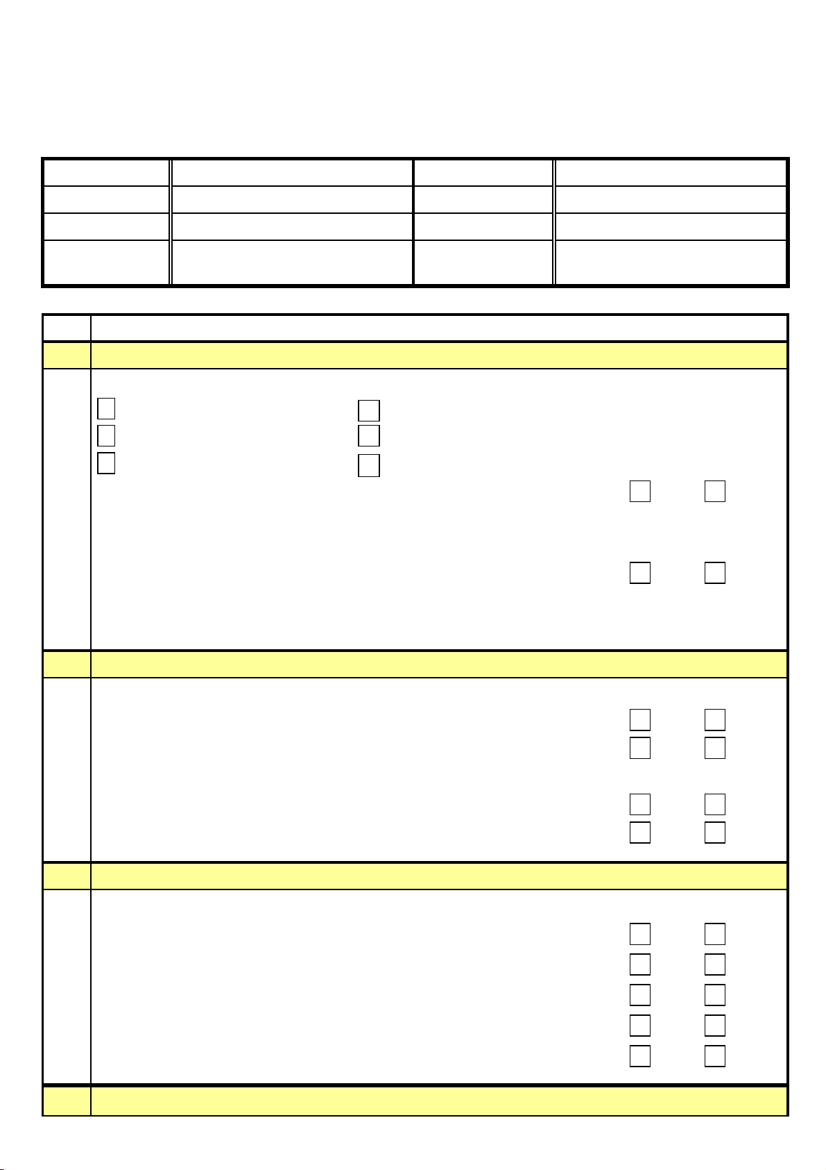
Small SB-Flat Installation Report
Order
1Check the installation environment before installing the machine
First Condition of the machine when techncian arrived at the plant
Start from opening the wood box when the machine is being moved to inside
Machine ready to be installed During the machine assembly (process name: )
Machine assembly completed Other ( )
(1) Temperature, Humidity and Others Pass Fail
(2) On which floor :
(3) Material of the floor :
(4) Levelness on Floor Pass Fail
(5) Machine Voltage Specification :
6) Input Voltage : 1P ( V )
2Check machine installation and exterior conditions
(1) Machine Installation
- Check Machien Levelness Pass Fail
- Adjust Machine Levelness by Leveling Bolt in case it is not correct. Pass Fail
(2) Check X-Frame Movement
- Check X-Frame Movement Pass Fail
- Check it after adjsuting Sensor Bracket position if it is not proper. Pass Fail
3Machine TEST
Machine TEST after Installation
(1) JUMP TEST Pass Fail
(2) WIPER TEST Pass Fail
(3) PICKER TEST Pass Fail
(4) TRIM TEST Pass Fail
(5) THREAD SENSING TEST Pass Fail
4Check Needle Drop Position
M/C Type
Serial No.
Version Date
Installation
Technician
Country
Agent
Customer
Installation Date
Items to be Checked
Page 10 Of 11 (주) SUNSTAR SWF CS Center
Table of contents
Other SWF Sewing Machine manuals


