Swoffer Instruments 3000-STDX Installation guide

MODEL 3000-STDX, 3000-LX,
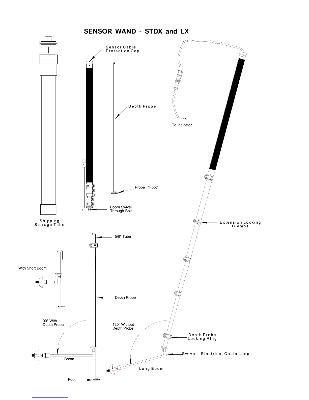
Sensor Wand Operation and Maintenance
(See separate documents for Indicator operating instructions)
EXTENDING THE SENSOR WAND
The Sensor Wand is lengthened by loosening the hose clamps, pulling the telescoping sections apart
to the desired length, then re-tightening the clamps. A 5/16" nut-driver is supplied to operate the
clamps, however a screwdriver or coin may also be used.
A red painted groove is cut into each telescoping section indicating the maximum recommended
extension but no stop is provided and each section can pull out of the other if extended too far.
Carefully re-insert the section if separation occurs. NOTE: When shortening the wand it is important
to continually take up all the slack in the cable to prevent binding of the telescoping sections.
USE OF THE DEPTH PROBE
If the depth probe is desired the last (smallest) section of the wand must be extended to its
maximum length. The sensor must also be swiveled from the "stowed" position to the 90° "read"
position. Next slide the depth probe up through the 1/4" hole in the back of the sensor swivel and
screw the threaded end of the probe into the sliding collar. Raise or lower the depth probe using the
collar until the probe allows the sensor to rest at the desired depth from the stream bottom. To lock
the collar in position use the 5/16" hex head wrench and tighten the lock nut on the collar.
OPERATION WITH THE MODEL 3000 CURRENT METER
Connect the sensor to the indicator via the twist-lock connector. Swivel the sensor boom to the
desired angle (90° only when using the depth probe) and point the propeller into the stream flow.
The Model 3000 Indicator is now ready to compute velocity. NOTE: This is the rudimentary form of
operation of the current meter. For the complete capabilities and options of the instrument see the
accompanying MODEL 3000 INDICATOR OPERATION INSTRUCTIONS.
3.170"
1.975"
0.500
2100-A22, Sensor Body & Cable
2100-A23
2100-Prop
2100-A25
2100-A26
2100-A27
2100-A21

MODEL 3000-STDX, 3000-LX / WAND OPERATION / PAGE
2
OF 4
CARE OF THE SENSING WAND AND THE PHOTO-FIBER-OPTIC SENSOR
1. After each day's use extend the wand sections completely and wipe all surfaces dry. This
will reduce corrosion and prevent future difficulty in lengthening the sections. If possible
allow the sections to completely air dry before collapsing and storing the wand. A light film of
oil or silicone grease will help the sections slide and helps to prevent the normal corrosion
which occurs.
2. Treat the sensor boom gently. When swiveling into and out of position grasp only the BOOM,
not the SENSOR BODY or PROPELLER ASSEMBLY. The sensor swivel can be tightened by
adjusting the through-bolt and nut (see back page diagrams).
3. Take care that the electrical cable loop which passes through the sensor swivel does not
protrude from the groove provided for the cable. Carefully take up the slack in the cable when
the loop extends beyond the back side of the swivel bar.
4. The electrical connector is water resistant at the mating faces only and then only when the
two halves are mated. Keep both ends as dry as possible when not in use.
CARE OF THE 3000 (2100) SENSOR
The Sensor of the Model 3000 Current Meter is the single most important part of the
instrument and great care must be observed for its continued accurate output.
Keep the Sensor/Propeller assembly above the stream bed when taking readings and avoid rocks and other
hazards when moving from one measuring site to another. This will prevent damage to the Rotor, Rotor
Shaft, Propeller and the Sensor Body.
Never transport or store the sensor wand with the propeller rotor installed.Use the 1/16" hex
screwdriver to loosen the set screw and remove the entire rotor assembly when not using the Model 3000.
Always replace the batteries in the Model 3000 Indicator with fresh ones.
1. During rough use check the propeller frequently for frayed leading edges and for cracks. Chipped or
cracked props should be replaced. Frayed leading edges can be brought back to acceptable levels of
operation by reshaping them with 150 grit (or finer) sandpaper. Propellers which show signs of being
bent or misshapen should be discarded.
2. Rotational friction is by far the biggest cause of erroneous data especially at velocities below 2 feet
per second. Check the freedom of rotation frequently especially in turbid water or after rough
handling. In some measuring situations it may be necessary to completely disassemble the rotor and
clean the parts with clear water after each immersion. Use spare rotor assemblies and interchange
them often. Never leave the rotor assembly attached to the sensor after taking readings.
3. Water is the lubricant for the 2100 rotor. "Canned air" and spray type degreasers should be used to
regularly clean the "bore" of the Rotor (2100-A27) and the polished surface of the Rotor Shaft (2100-
A26). Avoid oil & grease if possible.
4. The Rotor Assembly (2100-A21) should spin very freely when held in the vertical position (propeller
pointing up) and simply blow lightly on the propeller. If it does not, clean the bore of the Rotor and
the surface of the Rotor Shaft thoroughly.
One method to determine an acceptable level of low-velocity performance by a particular Rotor
Assembly is to perform a "Spin Test":
Install the Rotor on the sensor, connect the sensor to the Indicator, and place the Indicator in the
COUNT mode. With the propeller pointing upward, blow very hard straight down on the propeller. At
the instant you stop blowing hit the ENTER key on the indicator and allow the rotor to coast to a stop.

MODEL 3000-STDX, 3000-LX / WAND OPERATION / PAGE
3
OF 4
A rotor which will perform to the low velocity limits of its design produces counts on the indicator of
at least 300.
5. If the Rotor begins to "buzz" when spun by hand it means that the bore diameter of the Rotor (2100-
A27) and the outside diameter of the Shaft (2100-A26) are too far apart. In this case it is advised to
replace the Rotor with a new one. If the shaft shows visible signs of wear replace it also. Severe
buzzing indicates that the rotor is bouncing off the shaft as it rotates around it. This slows the rotor
significantly especially at velocities above 3 FPS and will cause readings to be slower than actual.
Note: Some slight buzzing may be heard in the later versions of the rotor when it is spun "dry". This
buzzing should cause no significant loss of efficiency.
6. Periodically examine the Thrust-Bearing Nut (2100-A23) and check inside on the bottom (the bearing
surface). If a pronounced "cup" begins to form (wear from the ball-shaped end of the Rotor Shaft)
the 2100-A23 should be replaced. This is especially necessary when using the Model 3000 in low-
flow situations, 2 FPS or lower.
7. The Photo-Optics in the sensor body must be kept clean. Use soap and water and a soft tooth brush
to keep the "eyes" clean if necessary. Be careful and do not scratch the Photo-optics as this could
cause unwanted light scattering and therefore erroneous readings. Likewise the Fiber optics "eyes" in
the base of the Rotor (2100-A27) should also be kept clean.
Treat the Model 2100 Rotor Assembly and Sensor with care and it will continue to produce accurate data
with minimum maintenance.
SWOFFER INSTRUMENTS, INC.
1112 S. 344th St., Suite 302
Federal Way, WA 98003 U.S.A.
FAX (253) 661-8711
(253) 661-8706
www.swoffer.com
MODEL 3000-STDX, 3000-LX / WAND OPERATION / PAGE
4
OF 4
This manual suits for next models
1
Table of contents
Other Swoffer Instruments Accessories manuals


