SYCLOPE electronic COOLTouch How to use

Installation and starting instructions
SYCLOPE COOLTouch® Controller for Cooling tower managements (Part 1)
Installation and starting instructions
Reference: DOC0484 Rev: 1

General information Page 2/57
Installation and starting instructions
Part of the general documentation
Part 1: Installation and starting instructions
Part 2: General programming instructions
Part 3: Communication programming instructions
General information:
SYCLOPE Electronique 2021® Manual of 25/08/2021 Rev 1
Professional controller for cooling towers.
Product line COOLTOUCH®
Part 1: Installation and starting instructions (Ref: DOC0484)
Editor:
SYCLOPE Electronique S.A.S.
Z.I. Aéropole Pyrénées
Rue du Bruscos
64 230 SAUVAGNON - France –
Tel: (33) 05 59 33 70 36
Fax: (33) 05 59 33 70 37
Email: syclope@syclope.fr
Internet: http://www.syclope.fr
© 2021 by SYCLOPE Electronique S.A.S.
Subject to modification
►

Contents Page 3/57
Installation and starting instructions
Contents
I. Generality...................................................................................................................... 5
1) Scope ................................................................................................................................5
2) FCC conformity...................................................................................................................6
3) Use of the document ..........................................................................................................7
4) Symbols and signs ..............................................................................................................7
5) Storage and transport .........................................................................................................8
6) Packaging ..........................................................................................................................8
7) Warranty ...........................................................................................................................8
II. Safety and environmental instructions ......................................................................... 9
1) Use of the equipment .........................................................................................................9
2) User obligations .................................................................................................................9
3) Risk prevention ..................................................................................................................9
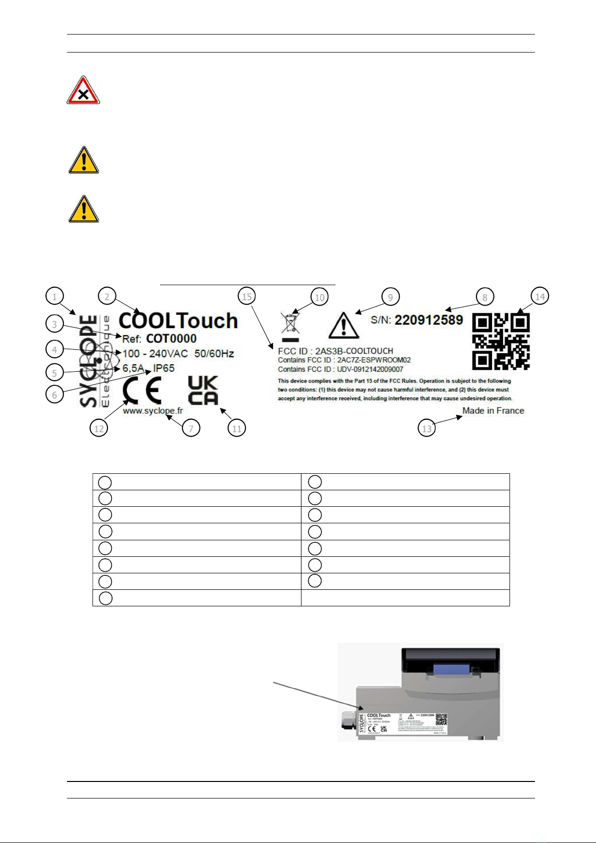
4) Identification and location of nameplate ............................................................................ 10
5) Disposal and conformity .................................................................................................... 11
III. Technical characteristics and functions ......................................................................12
1) Technical characteristics ................................................................................................... 12
2) Main functions .................................................................................................................. 13
3) Radio technologies in equipment ....................................................................................... 13
4) Parameters and measurement scales ................................................................................. 13
IV. Installation et connections .........................................................................................16
1) Installation conditions ....................................................................................................... 16
2) Wall installation of the device ............................................................................................ 16
3) Open / Close transparent door .......................................................................................... 17
4) Open / Close the terminal cover ........................................................................................ 17
5) Tightening torque ............................................................................................................. 18
a) Cable gland ............................................................................................................. 18
b) Terminal blocks ....................................................................................................... 18
6) Electrical connections ....................................................................................................... 18
7) Changing the internal fuse of PO1 output .......................................................................... 19
8) Primary power connections ............................................................................................... 20
9) Measurement inputs connections ....................................................................................... 21
a) PT100 / Pt1000 input RI1 ........................................................................................ 21
b) Conductivity input RI2 ............................................................................................. 21
c) Isolated analog inputs 4…20mA AI1 & AI2 ................................................................ 22
d) Digital inputs DI1 to DI5 .......................................................................................... 23
e) Serial input SI1 ....................................................................................................... 24
10) Self-powered relays outputs connections PO1 .................................................................... 25
11) Potential-free relay connections (FO1 to FO4) .................................................................... 25
12) Electronic relay outputs connections RO1 ........................................................................... 27
13) 4…20mA outputs connections (AO1 to AO2) ...................................................................... 28
14) Power supply output connection (PWR) ............................................................................. 29
15) RS485 communication bus connections .............................................................................. 30
a) Connection to a USB port on a computer .................................................................. 30
b) Polarization and termination of the RS485 bus .......................................................... 31
V. General use .................................................................................................................32
VI. Commissioning the SYCLOPE COOLTouch® ................................................................33
VII. Display mode and type................................................................................................34

Contents Page 4/57
Installation and starting instructions
1) Main screen display .......................................................................................................... 34
a) The upper banner.................................................................................................... 34
b) Display details of the channels ................................................................................. 37
2) “Detailed” display of a channel .......................................................................................... 38
a) Bleed valve ............................................................................................................. 38
b) Water flow switch .................................................................................................... 39
c) Biocide ................................................................................................................... 39
d) Inhibitor / Dispersant ............................................................................................... 40
e) Dosing mode ........................................................................................................... 40
f) Tower management ................................................................................................ 41
3) Graphical part .................................................................................................................. 42
VIII. Input mode .................................................................................................................43
1) Setup or Settings code entry screen .................................................................................. 43
2) Numerical value entry screen ............................................................................................ 43
3) Alphanumeric keyboard .................................................................................................... 44
a) « Shift » key ........................................................................................................... 44
b) « Caps lock » key .................................................................................................... 44
c) « Keyboard type » key ............................................................................................. 44
d) « Other characters » key ......................................................................................... 45
e) « Back » key ........................................................................................................... 45
f) « Enter » key .......................................................................................................... 45
g) « Close » key .......................................................................................................... 45
h) Special case of access to accented character keys. .................................................... 45
4) Main input elements ......................................................................................................... 46
a) Opening a selection list ............................................................................................ 46
b) Multi selection button .............................................................................................. 46
c) Unique selection button ........................................................................................... 46
d) Input button ........................................................................................................... 46
e) Action button .......................................................................................................... 46
f) Selection list............................................................................................................ 47
g) Navigation bar ......................................................................................................... 48
h) Lock symbol ............................................................................................................ 48
IX. Annexes ......................................................................................................................49
5) “Configuration & Installation” – “Reset Factory” menu [0831] ............................................. 49
6) « User » - « DATE & TIME » menu [0311] ......................................................................... 52
7) Backup battery change ..................................................................................................... 54

Generality Page 5/57
Installation and starting instructions
I. Generality
1) Scope
The range of SYCLOPE COOLTouch® controller you have purchased is a high-tech electronic device for
the complete management of cooling tower (air/water coolers) and the risks related to the legionella.
Its remarkable adaptability to the various structures of cooling towers enables him to settle in all the
difficult cases where the control of the process and the water treatment in a cooling tower are decisive.
Designed according to the needs of the customer, the COOLTouch® controller is equipped analogical
and numeric inputs for specific sensors for treating water in a cooling tower and also include alarm
functions and various controls with cyclic commands transmitted by means of programmable relays to
control specific dosing systems used for chemical treatments.
The simplicity of the COOLTouch® controller operations, the user friendliness and the remarkable
technical aspects of these controllers, will ensure you benefits from their many options, guaranteeing you
full control and supervision of the quality of the water.
The following instructions contain all the information required for installation, use and maintenance of
your new equipment.
Installation
Technical specifications
Commissioning instructions
Safety tips
If you would like to receive further information or if you encounter any difficulties not described in this
manual, please contact your usual retailer or else directly contact the sales department of SYCLOPE
ELECTRONIQUE S.A.S., either at the agency or at the office for your region, or the technical/quality
departments of our establishments. We will do everything in our power to help you and ensure your
benefit from our advice and know-how in the field of measurement and treatment of swimming-pool
water.
Contact: Service-technique@syclope.fr

Generality Page 6/57
Installation and starting instructions
2) FCC conformity
The SYCLOPE COOLTouch® controller complies with Part 15 of the FCC Rules.
Operation is subject to the following two conditions:
(1) this device may not cause harmful interference (2) this device must accept any interference received,
including interference that may cause undesired operation FCC Regulations state that unauthorized
changes or modifications to this equipment may void the user’s authority to operate it.
This equipment has been tested and found to comply with the limits for a Class B digital device, pursuant
to Part 15 of the FCC Rules. These limits are designed to provide reasonable protection against harmful
interference in a residential installation. This equipment generates, uses, and can radiate radio frequency
energy and, if not installed and used in accordance with the instructions, may cause harmful interference
to radio communications. However, there is no guarantee that interference will not occur in a particular
installation.
If this equipment does cause harmful interference to radio or television reception, which can be
determined by turning the equipment off and on, the user is encouraged to try and correct the
interference by one or more of the following measures:
Reorient or relocate the receiving antenna.
Increase the separation between the equipment and receiver.
Connect this equipment into an outlet on a circuit different from that to which the receiver is
connected.
Consult the dealer or an experienced radio/TV technician for help.
Changes and modifications not expressly approved by the manufacturer could void the user’s authority
to operate this equipment.
Remark: To ensure compliance with the FCC regulations on electromagnetic interference for a class B
device, use cables properly shielded and connected to the ground as recommended in this manual. The
use of a cable that is not properly shielded or earthed for risk of violating the FCC rules.
Radio Frequency (RF) Exposure Compliance of Radiocommunication for mobile Apparatus To satisfy FCC
RF Exposure requirements for mobile devices, a separation distance of 20 cm or more should be
maintained between the antenna of this device and persons during operation. To ensure compliance,
operation at closer than this distance is not recommended. This transmitter must not be co-located or
operating in conjunction with any other antenna or transmitter.
Contains:
- WiFi module: FCC ID : 2AC7Z-ESPWROOM02
This device complies with part 15 of the FCC Rules. Operation is subject to the following two conditions:
(1) This device may not cause harmful interference, and (2) this device must accept any interference
received, including interference that may cause undesired operation.
- GSM module: FCC ID: UDV-0912142009007
This device complies with part 15 of the FCC Rules. Operation is subject to the following two conditions:
(1) This device may not cause harmful interference, and (2) this device must accept any interference
received, including interference that may cause undesired operation. (for FCC)

Generality Page 7/57
Installation and starting instructions
3) Use of the document
Please read carefully the entire document before starting the installation and the commissioning of the
controller device, in order to ensure the safety of swimmers, users and equipment’s.
The information provided in this document must be strictly observed. SYCLOPE Electronique S.A.S.
declines all responsibility in cases where failure to comply with the instructions of this documents.
The following symbols and pictograms will be used to facilitate reading and understanding of these
instructions.
● Information
► Action to do
Element of a list or enumeration
4) Symbols and signs
Identification of a continuous volage or current
Identification of an alternative voltage or current
Protective ground
Functional ground
Risk of injury or accident. Identifies a warning concerning a potentially dangerous risk. The
documentation must be consulted by the user with each time the symbol is notified. If the
instructions are not respected, this presents risks of death, physical injuries or property
damages.
Electric hazard. Identifies a warning statement relative to a mortal electric danger. If the
instructions are not strictly respected, this implies an inevitable risk of physical injuries or death.
Risk of incorrect operation or damage for the device
Comment or particular information.
Recyclable element

Generality Page 8/57
Installation and starting instructions
5) Storage and transport
It is important to store and to transport the SYCLOPE COOLTOUCH controller in its original
packaging in order to minimize risk of damage.
Furthermore, the package must be stored in an environment that is protected against humidity
and exposure to chemical products.
Environmental conditions for transport and storage:
Temperature: -10 °C à 70 °C
Air humidity: Maximum of 90% with no condensation
6) Packaging
The device is delivered without power cable.
Caps of the box are pre-drilled and fitted with corresponding cable glands conform to the
maintenance of IP65 protection. Cables used must be adapted to them in order to respect the
portion index.
Shielded cables for connecting pH and ORP electrodes are not supplied.
The controller is delivered with:
SYCLOPE COOLTouch® central controller
Installation and starting instructions
General programming instructions
Communication programming instructions (Option)
7) Warranty
The warranty is provided according to the terms of our general conditions of sale and delivery as
long as the following conditions are met:
Use of the equipment according to the instructions of this notice
No modifications of the equipment which may modify its behaviour and no incorrect
manipulation
Respect for the electrical safety conditions
Consumable material is no longer covered by warranty as soon as it’s put into service.

Safety and environmental instructions Page 9/57
Installation and starting instructions
II. Safety and environmental instructions
Please:
Read this manual carefully before the unpacking, the installing or the commissioning of this
equipment
Take into account all the hazards and of recommended precautionary measures
The failure to respect these procedures can result in serious injury to users or damaging the device.
1) Use of the equipment
SYCLOPE COOLTouch® controller is a microprocessor equipment generating all necessary functions to
control a cooling tower.
All other uses are considered to be non-conforming and must therefore be forbidden. SYCLOPE
Electronique S.A.S. will not be responsible in any case for any damage that result from such
uses.
The 12V Ext must not be used when the product is connected to an electrical network within
the following range: 100 – 208V
Do not use the device for measurements on the network directly, but only on the secondary
circuit under very low safety voltage.
2) User obligations
The user undertakes not to allow its employees to work with the SYCLOPE COOLTouch® controller
described in this manual unless they:
Are aware of the fundamental instructions relating to work safety and prevention of accidents
Are trained in the use of the device and its environment
Have read and understood these instructions, warnings and manipulation rules
3) Risk prevention
The installation and connection of the SYCLOPE COOLTouch® controller should be only
performed by specialized personnel and qualified for this task.
The installation must comply with the current safety standards and instructions!
Before opening the controller or manipulate the relay outputs, always remember to switch-off
the primary power supply!
Never open the controller when it is powered on!
Maintenance operations and repairs should be only performed by trained and specialized
personnel!

Safety and environmental instructions Page 10/57
Installation and starting instructions
Take care when choosing the location for installing the controller!
SYCLOPE COOLTouch® controller should not be installed in a hazardous environment and
should be protected against splashing with water or chemical products. It should be installed in
a dry, well-ventilated and isolated location.
Make sure that the chemical sensors used with this controller correspond well to the chemicals
used. Refer to the individual technical note of each sensor. Chemistry of water is very complex,
in case of doubt, contact immediately our engineering service or your approved installer/reseller.
Chemical sensors are sensitive elements using consumable parts. They must be supervised,
maintained and calibrated regularly using specific calibrator systems not-provided with this
equipment. In the event of defect, a surplus possible hazard of chemical injections can be noted.
In the doubt, a service contract must be taken near your reseller/installer or failing this near
our engineering services. Contact your approved installer/reseller or our business service for
more information.
4) Identification and location of nameplate
Manufacturer’s label Particular risk. Read the manual
Model of the product / Trade Mark Product which can be recycled
Reference of the product UKCA approved
Range of power supply CE approved
Values of maximum current Country of manufacture
Class of protection Manufacturer square code
Identification of the manufacturer FCC ID
Serial number
1
2
3
4
5
6
9
7
8
10
11
12
13
14
15
1
1
1
2
3
4
5
6
7
8
9
1
0
1
2
1
3
1
4
1
5
Nameplate

Safety and environmental instructions Page 11/57
Installation and starting instructions
5) Disposal and conformity
The recyclable packaging of the SYCLOPE COOLTouch® equipment must be disposed of according to
current regulations.
Elements such as paper, cardboard, plastic or any other recyclable elements must be taken to
a suitable sorting centre.
According to European directive 2012/19/EC, this symbol means that as of 4 July 2012 electrical
appliances cannot be thrown out together with household or industrial waste. According to
current regulations, consumers within the European Union are required, as of this date,
to return their used devices to the manufacturer, who will take care of disposing them at no
extra expense.
According to European directive 2011/65/EC, this symbol means that the SYCLOPE
COOLTouch® controller is designed in compliance with the restrictions on hazardous
substances.
According to low-voltage directive (2014/35/UE) and the electromagnetic compatibility directive
(2014/30/UE), this symbol means that the device has been designed in compliance with the
previously cited directives.
In accordance with part 15 of the FCC regulation (Federal communications commission), this
symbol indicates that the device was tested and approved under the respect and the conditions
of the limits for a Class B digital device.
The product complies with the requirements of IEC 61326-1 relating to immunity and emissions
concerning electromagnetic compatibility in a basic environment.
According to low-voltage directive (2014/35/UE) and the electromagnetic compatibility directive
(2014/30/UE), this symbol means that the device has been designed in compliance with the
previously cited directives.

Technical characteristics and functions Page 12/57
Installation and starting instructions
III. Technical characteristics and functions
1) Technical characteristics
Main features
Type(s) Specification(s) Marker(s)
Consumption 6,5A Max (Without connected dosing accessories)
-
Power supply requirements 100 - 240 VAC (± 10%) 50/60Hz
-
Electrical protection Fuse 550mA, Reset by power interruption
F4 & F5
Operating temperature (°C) -5 °C to 45 °C (23 °F to 113 °F) -
Case material Polycarbonate -
Dimensions of the case
Length: 280 mm (11 inches)
Width: 219 mm (8.6 inches)
Height: 156 mm (6.1 inches)
-
Case weight empty 0,850 kg -
Indicator light (LED) Group 0
Display 5-inch color LCD screen Resistive touch -
Environment
Storage temperature -10 °C to 70 °C (10 °F to 158 °F) -
Max operating altitude 2000 meters
Humidity Max. 90% without condensation -
Protection rating IP 65 -
Product certification CE -
Max overvoltage category of
the power supply network CAT II
Pollution degree DP 2
Electromagnetic
compatibility
Class B disruption tests comply with EN61326-1
Class B disruption tests comply with EN61326-2-6
Class B disruption tests comply with EN55011
Harmonics tests comply with EN61000-3-2
Harmonics tests comply with EN61000-3-3
Immunity tests comply with EN61000-4-2
Immunity tests comply with EN61000-4-3
Immunity test EN61000-4-4
Immunity tests comply with EN61000-4-5
Immunity tests comply with EN61000-4-6
Immunity tests comply with EN61000-4-8
Immunity tests comply with EN61000-4-11
-
Standard
EN 61000 Electromagnetic compatibility (CEM)
EN 61326 Electrical measuring, control and laboratory equipment
for a standard environment (class B home use)
-
Inputs
RTD (Pt100 / Pt1000) 1 isolated input (Impedance Pt100 : 100 to 138 Ω ; Pt 1000 :
1000 to 1385 Ω)
RI1
Contictivity input 1 isolated input (Impedance 40Ω to 1MΩ) RI2
4-20mA Inputs 2 Isolated inputs 24VDC no-load
(0 to 25 mA ; Insulation 35VDC ; Impedance 160Ω)
AI1 & AI2
Digital inputs 5 inputs (0 ro 12 VDC ; Non-isolated ; Impedance 5kΩ) DI1 to DI5
Serial input 1 input UART 5V TTL SI1
USB inputs USB connector on front (Exclusive use of USB key for Firmware
Update) (5VDC ; 500mA)
-
Outputs
Relay outputs 1 self-powered relay output 3A Max ; 240VAC Max PO1
Relay outputs 4 ON/OFF relay outputs 3A Max ; 48VAC Max FO1 to FO4

Technical characteristics and functions Page 13/57
Installation and starting instructions
Relay outputs 1 electronic relay output 50mA Max ; 48VAC Max RO1
Analog outputs 2 0/4…20 mA analog outputs Max ; 12VDC Max ; 500 Ω AO1 & AO2
Power output 1 24V power output ; 100mA
Communication port
RS485 1 RS485 communication port RS485
Ethernet 1 Ethernet output ETH
Protection of dosing outputs
Internal fuse 1 TR5 3,15 A 250 V Time delay fuses F2
Save
Button cell Type BR2032 Bat1
2) Main functions
Main functions
Function(s) Specification(s) Remark(s)
Controls Bleed and biocides controls According version
Type of actuators 1 Powered output relay 90~240V
5 Free of potential output relays
PWM or On/Off functions
Analogical outputs 2 0/4…20mA programmable outputs Copy or control functions
Purge Bleed-off function By setting conductivity or volumetric
setpoints
3) Radio technologies in equipment
Radio technologies
Technologies Number of
antenna
Radiated powers Frequency bands of use
WIFI 1 < 20dBm
2400 MHz to 2483.5 MHz
2.4 GHz Band
Exclusion Band :
[2280 MHz – 2603.5 MHz]
2G GSM900 0 33dBm 900MHz
DCS1800 30dBm 1800MHz
4) Parameters and measurement scales
Measures and regulations
Parameters Measuring scale Customer measuring scale
Accuracy
Temperature
-5 to 45°C ± 0,5 %
0 to 100 °C ± 0,5 %
-10 to 100°C ± 0,5 %
pH
0 to 14 pH ± 0,5 %
1 to 12 pH ± 0,5 %
-1 to 15 pH ± 0,5 %
ORP
0 to 1000 mV ± 0,5 %
-1000 to 1000 mV ± 0,5 %
Free chlorine
0,01 to 0,5 mg/l ± 0,5 %
0,02 to 2 mg/l ± 0,5 %
0,05 to 5 mg/l ± 0,5 %
0,1 to 10 mg/l ± 0,5 %
0,2 to 20 mg/l ± 0,5 %
0,5 to 50 mg/l ± 0,5 %
1 to 100 mg/l ± 0,5 %

Technical characteristics and functions Page 14/57
Installation and starting instructions
0 to 2000 mg/l ± 0,5 %
Active chlorine
0,02 to 2 mg/l ± 0,5 %
0,1 to 10 mg/l ± 0,5 %
0 to 2000 mg/l ± 0,5 %
Total chlorine
0,01 to 0,5 mg/l ± 0,5 %
0,02 to 2 mg/l ± 0,5 %
0,05 to 5 mg/l ± 0,5 %
0,1 to 10 mg/l ± 0,5 %
0 to 2000 mg/l ± 0,5 %
Chlorite
0,01 to 0,5 mg/l ± 0,5 %
0,02 to 2 mg/l ± 0,5 %
0 to 2000mg/l ± 0,5 %
ClO2 (Chlorine dioxide)
0,01 to 0,5 mg/l ± 0,5 %
0,02 to 2 mg/l ± 0,5 %
0,1 to 10 mg/l ± 0,5 %
0 to 2000 mg/l ± 0,5 %
H2O2 (Peroxide)
0,5 to 50 mg/l ± 0,5 %
2 to 200 mg/l ± 0,5 %
20 to 2000 mg/l ± 0,5 %
0 to 2000 mg/l ± 0,5 %
BCDMH
0,02 to 2 mg/l ± 0,5 %
0,2 to 10 mg/l ± 0,5 %
0,4 to 15 mg/l ± 0,5 %
0 to 2000 mg/l ± 0,5 %
DBDMH
0,1 to 1 mg/l ± 0,5 %
0,1 to 5 mg/l ± 0,5 %
0,1 to 10 mg/l ± 0,5 %
0 to 2000 mg/l ± 0,5 %
Free bromine
0,1 to 1 mg/l ± 0,5 %
0,1 to 5 mg/l ± 0,5 %
0,1 to 10 mg/l ± 0,5 %
0 to 2000 mg/l ± 0,5 %
Peracetic Acid
2 to 200 mg/l ± 0,5 %
10 to 2000 mg/l ± 0,5 %
0 to 2000 mg/l ± 0,5 %
Ozon 0,1 to 2 ppm ± 0,5 %
0 to 2000 ppm ± 0,5 %
O2 (Oxygen)
0,2 to 10 ppm ± 0,5 %
0,2 to 20 ppm ± 0,5 %
0 to 2000 ppm ± 0,5 %
PHMB 1 to 100 mg/l ± 0,5 %
0 to 2000 mg/l ± 0,5 %
Turbidity 0,2 to 100 NTU ± 0,5 %
0 to 2000 NTU ± 0,5 %
Conductivity
0 to 5 mS/cm ± 0,5 %
0 to 10 mS/cm ± 0,5 %
0 to 20 mS/cm ± 0,5 %
0 to 50mS/cm ± 0,5 %
0 to 100 mS/cm ± 0,5 %
0 to 2000 mS/cm ± 0,5 %
Flowrate
0 to 20 l/min ± 0,5 %
0 to 50 l/min ± 0,5 %
0 to 200 l/min ± 0,5 %
0 to 2000 l/min ± 0,5 %
Volume 0 to 2000 l ± 0,5 %

Technical characteristics and functions Page 15/57
Installation and starting instructions

Installation and connections Page 16/57
Installation and starting instructions
IV. Installation et connections
1) Installation conditions
To guarantee the user safety and to ensure correct operation of your SYCLOPE COOLTouch®,
please observe the following installation instructions:
Install the controller in a dry location
The controller must be protected against rain, frost and direct sunlight
The room temperature must range between -5°C and 45°C, with no condensation
Choose an installation location free from vibration, on a suitable support and with no
deformation
Install the device so that it does not make it difficult to operate the disconnecting circuit
(fuse or circuit breaker)
If these instructions are not observed:
The controller risks to be damaged,
The measurements can be disrupted,
The warranty is not applicable!
2) Wall installation of the device
Prior to installing the devices and connections of cables, pipes and fittings, cut power supplies!
The IP54 protection class is guaranteed only if the closure caps of the SYCLOPE COOLTouch®
are closed and the wires correspond to the diameter of the cable gland!
► Drill 3 holes 5 mm in accordance with the drilling plan below:
► Introduce the 5mm dowels using a hammer
► Fix the top screw first without tightening it completely
► Place the lower screws and tighten them
► Tighten the upper screw
► Make sure the housing is stable and level
242
189,5
199,5

Installation et connections Page 17/57
Installation and starting instructions
3) Open / Close transparent door
In order to guarantee IP65 class, the transparent door must absolutely be closed after use while
ensuring the quality of the closure seal.
The case has a closing system with automatic locking as soon as its handling is carried out
correctly.
To open the transparent door:
Door locked …
Lift the lock and pull towards
the front of the device
Door opened!
To close and lock the transparent door:
Put your fingers behind the
lock, and bring the door with
your thumb…
With the palm of your hand,
press on the transparent door
and tighten with your hand to
lock.
Door locked!
4) Open / Close the terminal cover
In order to guarantee IP65 class, the terminal cover must absolutely be closed after use while
ensuring the quality of the closure seal.
Use an appropriate screwdriver to unscrew the 2 fixing screws and open the terminal cover.

Installation and connections Page 18/57
Installation and starting instructions
5) Tightening torque
a) Cable gland
b) Terminal blocks
The tightening torque of the screws of different terminal block is 0.5 N.m
6) Electrical connections
Electrical installations must be carried out in accordance with the standards in force and by
authorized personnel!
A 30-mA differential circuit breaker must be installed!
A 10A circuit breaker must be installed near the device and easily accessible in order to cut the
primary supply. It must be marked as the cut-off circuit of the device.
Before making the connections, cut off the power supplies!
Preferably use single-strand cables
Otherwise, it is essential to use a crimped cable ends to ensure that no strand can come into
contact with neighbouring cables!
Secure the wire connections on the terminal blocks using a cable tie.
SYCLOPE COOLTOUCH® must be slaved to the filtration of the swimming pool using digital
input.
Internal protection:
SYCLOPE COOLTouch ® is protected by two resettable fuses (see table “General
characteristics” page 14) and by a varistor against overvoltage of 275V.
The self-powered power relay outputs PO1 is protected by a TR5 fuse (see table “General
characteristics” page 14).
Max cable section via
cable gland. 3 x (2-5mm) 1 x (9,4-12mm)
Cable gland
tightening torque. 0.7 N.m 2 N.m

Installation and connections Page 19/57
Installation and starting instructions
7) Changing the internal fuse of PO1 output
SYCLOPE COOLTouch ® has a spare fuse located in position F5, which allows you to quickly
replace a fuse if necessary. If you are led to using it, don’t forget to replace it…
Cut off the power supply, before changing the fuse!
Always use a fuse identical to the original one. Don’t replace with a higher intensity!
Cut off the power supply
Open the transparent door and unscrew the 4 front screws using an appropriate
screwdriver.
Carefully disconnect the connection flat cable connecting the bottom card and the upper
part of the device.
Fuse F2 (TR5)
Spare fuse F5 TR5

Installation et connections Page 20/57
Installation and starting instructions
Reconnect the flat cable between the cards and reassemble the front panel using the 4
fixing screws. Don’t overtighten because the screws are fixed in the plastic case.
Reconnect the flat cable and replace the front panel before switch On.
8) Primary power connections
SYCLOPE COOLTouch® has a switch-mode power supply. It can be powered by an
alternating voltage between 100V and 240V 50/60Hz.
► Use a 3-point 1.5 mm2 to wire the power supply
► Strip the 3 wires on 7mm
► Pass the 3-point cable through a cable gland
► Connect the phase on L1 and the neutral on the N of the main terminal block X1
► Connect the earth on the PL1 stud using an M4 eyelet terminal
► Tighten the cable gland to seal.
Your SYCLOPE COOLTouch® doesn’t have a power switch. So, it’s directly supplied when
it’s connected to the mains.
Your SYCLOPE COOLTouch ® doesn’t have a power switch. It is therefore necessary to
install a 10A circuit breaker upstream of the device.
Locate the fuse to be changed
on the lower PCB
Remove the fuse to be changed Replace the new fuse
Fuse F2 (TR5)
Table of contents
Other SYCLOPE electronic Controllers manuals
Popular Controllers manuals by other brands

ESKA
ESKA ERG-SR Instructions for installation, use and maintenance manual

GEM
GEM 9428 operating instructions

Conair
Conair Basic 32 Loader Control B32 user guide

Paso
Paso PMS2006-V Instructions for use

Brodersen
Brodersen RTU32S Series Installation and wiring guide

Enttec
Enttec DATAGATE MK2 Quick start manual

Mitsubishi Electric
Mitsubishi Electric SV13/22 Programming manual

Teracom
Teracom TCW110 user manual

Vadsbo
Vadsbo LCC60 installation instructions

Pentair
Pentair SOLARTOUCH 521592 Installation and user guide

CD Automation
CD Automation Revo TC Communications manual

Siemens
Siemens GAMMA wave GE 561/01 Technical product information